Elastic Response of Mesoporous Silicon to Capillary Pressures in the Pores
Abstract
We study water adsorption-induced deformation of a monolithic, mesoporous silicon membrane traversed by independent channels of 8 nm diameter. We focus on the elastic constant associated with the Laplace pressure-induced deformation of the membrane upon capillary condensation, i.e. the pore-load modulus. We perform finite-element method (FEM) simulations of the adsorption-induced deformation of hexagonal and square lattices of cylindrical pores representing the membrane. We find that the pore-load modulus weakly depends on the geometrical arrangement of pores, and can be expressed as a function of porosity. We propose an analytical model which relates the pore-load modulus to the porosity and to the elastic properties of bulk silicon (Young’s modulus and Poisson’s ratio), and provides an excellent agreement with FEM results. We find good agreement between our experimental data and the predictions of the analytical model, with the Young’s modulus of the pore walls slightly lower than the bulk value. This model is applicable to a large class of materials with morphologies similar to mesoporous silicon. Moreover, our findings suggest that liquid condensation experiments allow one to elegantly access the elastic constants of a mesoporous medium.
Mesoporous silicon (pSi) prepared by electrochemical etching of bulk silicon has been attracting much attention from both fundamental and applied sciences owing to its unique optical, electrical and thermal properties Canham (1990); Lehmann and Gösele (1991); Sailor (2012); Canham (2015a); Henstock et al. (2015); Huber (2015). While control over mechanical properties of pSi is necessary for its applications, the understanding of its response to mechanical loads is mainly limited to measuring Young’s modulus of porous samples Bellet et al. (1996); Populaire et al. (2003).
Since pSi can be prepared as a bulk (monolithic) mesoporous system with parallel, channel-like independent pores, it has been of a particular interest for studies of fluid adsorption Canham (2015a). On the one hand, this matrix allows one to study the influence of spatial confinement on the physics and chemistry of liquids Coasne et al. (2002); Wallacher et al. (2004); Hofmann et al. (2005); Naumov et al. (2008); Kumar et al. (2008); Henschel et al. (2009); Kärger and Valiullin (2014). On the other hand, it is possible to synthesize composite materials with finely tuned optical and electrical properties by liquid adsorption or infiltration Westover et al. (2014); Canham (2015a). Therefore, exploration of the mechanical properties of silicon relevant to interactions with liquids, the topic of this Letter, is also of high importance.
When a fluid is adsorbed in a mesopore, it exerts a pressure on the pore walls, which is typically of the order of Pa Gor and Neimark (2010). This pressure causes deformation of the pore, and as a result deformation of the porous material as a whole. This effect, known as adsorption-induced deformation has been experimentally observed for various mesoporous materials: Vycor glass Amberg and McIntosh (1952); Schappert and Pelster (2014), templated silica Günther et al. (2008); Prass et al. (2009); Balzer et al. (2015), low-k films Mogilnikov and Baklanov (2002); Dourdain et al. (2008), aerogels Reichenauer and Scherer (2001); Herman et al. (2006), porous gold Shao et al. (2010) and pSi Dolino et al. (1996). There are two ways to measure the adsorption strains experimentally: for materials which can be prepared as macroscopic samples, the dilatometric technique can be used, and the reported strain is the relative change of the length of the sample Amberg and McIntosh (1952); Reichenauer and Scherer (2001); Shao et al. (2010); Schappert and Pelster (2014). For crystalline materials or materials which have periodic pore structure, X-ray diffraction can be used, and the strain is calculated as a change of the crystal Dolino et al. (1996); Shao et al. (2010) or pore-spacing lattice constant Günther et al. (2008); Prass et al. (2009). Irrespective of the technique, the measured strains for all these materials (except for aerogels) are of the order of . Such small strains are in the linear elastic regime, and it is reasonable to assume a linear relation between the pressure in the pore and the experimentally observed strain with a proportionality constant , called the pore-load modulus Prass et al. (2009). If the pore-load modulus for a certain porous material is known, it is possible to calculate the fluid pressure in the pores based on the experimental data on adsorption-induced strain, providing information on the thermodynamics of the confined fluid. Also, understanding of elastic response of a porous material to adsorption is useful for its application to sensing and actuation Bertinetti et al. (2013); Zhao et al. (2014).
The pore-load modulus relates the pressure inside the pore to the overall deformation of the sample, rather than relating an external load to a deformation, like Young’s or bulk moduli. Therefore an important question is how to relate the pore-load modulus to the material properties of the matrix and the pore geometry. In general, for a material with a wide pore size distribution (PSD) and arbitrary pore morphology and orientation, this question may be complicated. However, for systems such as pSi considered in this work, where the geometry is regular, it can be resolved.
Here we present a dilatometric study of the deformation of a macroscopic pSi membrane induced by adsorption of water vapor. From the experimental strain isotherm we calculate the pore-load modulus. We perform FEM simulations of adsorption-induced deformation of samples with hexagonal and square lattices of cylindrical pores. We find that the pore-load modulus weakly depends on the geometrical arrangement of pores, and can be expressed as a function of porosity. Therefore we relate the deformation of a porous sample to the deformation of a single cylindrical tube from the pressure applied to its inner surface. Based on this model we derive an analytical expression for the pore-load modulus as a function of the porosity and the elastic properties of the non-porous material (Young’s modulus and Poisson’s ratio). The predictions of our analytical model are in excellent agreement with FEM results. We also achieve good agreement between our experiment and our analytical model for adsorption-induced deformation of pSi, suggesting that the Young’s modulus of silicon pore walls could be only slightly lower than the Young’s modulus of bulk silicon.
Adsorption-induced deformation of pSi has previously been studied by Dolino et al. Dolino et al. (1996). They obtained the strain normal to the plane of the sample from the shifts of X-ray diffraction peaks of the crystalline lattice of the silicon matrix, and calculated the normal-to-the-plane pore-load modulus from a comparison of the experimental strain to the fluid pressure in the gas pressure region, where the pores are filled with capillary condensate and the fluid pressure in the pore has a simple form. They also proposed an analytical expression for the pore-load modulus as a function of material parameters based on Scherer’s model for porous glasses Scherer (1986) and the theory of elasticity for cellular materials Gibson and Ashby (1999). However, their model did not agree with the experimental data. Recently Grosman et al. reported a dilatometric study of both the in-plane and normal-to-the-plane deformation of pSi induced by n-heptane adsorption Grosman et al. (2015). In this work the authors calculated the pore-load moduli for two samples, and proposed their own mechanical model to relate these moduli to the Young’s modulus of silicon. By applying their model to their experimental data the authors came to the conclusion that the Young’s modulus of silicon walls is lower than the Young’s modulus of bulk silicon by a factor of five.
Another attempt to relate the pore-load modulus to material parameters was made by Prass et al. Prass et al. (2009). They studied adsorption strains in MCM-41 and SBA-15 silica, which have morphologies similar to pSi, and proposed that the strain, derived from the change of the pore lattice parameter, behaves similarly to the hoop stress in thin-walled cylinders. Although that model provided good agreement with their experimental data, it was not consistent with their finite element method (FEM) calculations. Our model does not employ the thin-wall assumption and is fully supported with FEM calculations.
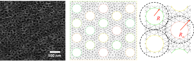
Mesoporous silicon was prepared by electrochemical etching of highly boron-doped (100) silicon wafers (producer: SiMat, Landsberg, Germany; specific conductivity: =0.01–0.025 cm). After an etching depth of 30m a high voltage was applied in order to remove the mesoporous part from the bulk silicon underneath. The resulting parallel, non-interconnected, tubular pores have a short-range hexagonal order. A scanning electron microscope (SEM) image of the sample is shown in Fig. 1.
The sample was cut in a rectangular shape with 4 mm 7 mm and a thickness of 30 m. The sample’s long axis was parallel to the crystallographic 010 direction. As prepared the inner pore walls are Si-H terminated. A 30 minutes infiltration of a peroxide/water solution and subsequent rinsing with Millipore water rendered the inner pore space Si-OH terminated, and thus hydrophilic. A volumetric nitrogen adsorption isotherm measurement performed at 77 K and analysed within the NLDFT model Landers et al. (2013) indicated a mean pore diameter of 8 nm (width of the PSD 15%) and a volume porosity of 60%.
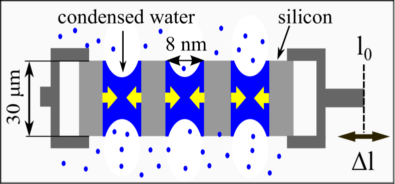
The measurements of the adsorption-induced strains were performed using a custom-made dilatometric setup, Fig. 2. The samples were tested in a sealed chamber, kept at a constant temperature of 24∘C by means of a water circulation thermostat (Huber). The humidity inside the chamber was controlled by means of a Wetsys (Setaram) humidity generator, which was working with a flow of 200 ml/min. The samples were clamped to two aluminium holders. The macroscopic deformation was measured by one of the holders that connects to a Physics Instruments M-404 linear motor stage (resolution of 2 m), while the axial tensile force was measured using a Honeywell R-30 load cell (50 N max. load), attached to the other holder. The standard deviation of the measured force background noise over more than 100,000 points was 10 mN. The strain of the sample was measured by driving the motors to keep a constant (small) force of 100 mN, while the humidity was continuously changed between 5% and 95% RH at a rate of 10% RH/h. The stress on the sample under these conditions is estimated to be lower than 0.5 MPa.
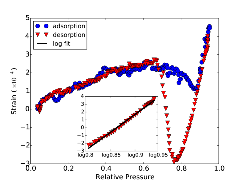
In Fig. 3 we show the experimentally measured, macroscopic strain of the sample as a function of relative vapor pressure (= relative humidity) ( is the saturation pressure of water at 24∘C). Here is the measured length change of the membrane and the length of the sample at RH=0%. The behavior observed is typical of adsorption-induced deformations of mesoporous materials and is due to the change of the pressure of the confined fluid (adsorption stress) in the mesopores Gor and Neimark (2010). The shape of the strain at low pressures (before the hysteresis loop related to capillary condensation) may differ and depends on the strength of the solid-fluid interactions Gor et al. (2013). At higher pressures, when the pores are filled with capillary condensate, the strain changes linearly with . This trend is not specific to pSi and has been observed for all mesoporous materials investigated so far Amberg and McIntosh (1952); Schappert and Pelster (2014); Dolino et al. (1996); Günther et al. (2008); Prass et al. (2009); Balzer et al. (2015); Mogilnikov and Baklanov (2002); Dourdain et al. (2008); Reichenauer and Scherer (2001); Herman et al. (2006); Grosman et al. (2015). In our case, this region corresponds to pressures . The strain for this region is shown in the inset of Fig. 3.
When a pore is filled with fluid, the pressure that the fluid exerts on a pore wall is given by Gor and Neimark (2010):
| (1) |
where is the solid-liquid surface energy, is the pore radius and is the Laplace pressure at the liquid meniscus. The latter can be written as (Kelvin-Laplace equation)
| (2) |
where is the gas constant, is the temperature and is the molar volume of the fluid. Since both the pressure in the pore and the experimentally measured strain of the porous sample as a whole vary linearly with , it is easy to get the pore-load modulus from the following relation , where is a constant, related to the surface energy of the solid-fluid interface. Although the value of is important for studying the thermodynamics of confined fluids Gor (2014), it does not affect the present discussion. Fitting of the data shown in the inset of Fig. 3 gives GPa.
The key problem is to find the relation between the pore-load modulus and the elastic constants of the non-porous material: Young’s modulus and Poisson’s ratio . We assume isotropic elasticity. Note that by the Young’s modulus we mean the modulus of the pore walls, and not the effective Young’s modulus of a pSi sample as a whole (), often reported in the pSi literature Canham (2015b). These two moduli should not be confused, since the latter is a property of a solid-void composite and is a strong function of the porosity Bellet et al. (1996); Magoariec and Danescu (2009).
The deformation of a system with multiple pores can be solved numerically using FEM Hecht (2012). Since for the considered material the PSD is narrow, the pores are parallel and distributed with a short-range hexagonal order, the pore-load modulus can be approximately calculated from deformation of a two-dimensional hexagonal lattice. The FEM representation of the problem is shown in Fig. 1. The left and bottom surface are constrained in the and directions respectively, while the right and top surface move freely. The pressure is applied in every pore, and the pore load modulus is estimated as the ratio of the applied pressure to the average engineering strain in the vertical direction. Poisson ratio was used, corresponding to bulk silicon properties Hopcroft et al. (2010). Systems of two different sizes, 5 8 (68 pores) and 10 16 (295 pores), were used to check for finite size effects. We found that the results for the larger system differs from the results for the smaller one by 2.5% at most. To evaluate the role of the lattice geometry we also performed the simulations on a square lattice 14 14 (296 pores); the difference between the modulus calculated for square and hexagonal lattices is 4% at porosities and 14% at .
The pore-load modulus calculated from FEM simulations is shown in Fig. 4. We see that the moduli for different lattice geometries are close, and for a given and depend mainly on porosity – the ratio of the volume of the voids to the total volume of the sample. For an analytical estimate of this dependence, we use the following considerations based on classical theory of elasticity. A single cylindrical pore with inner radius and pressure induces a purely deviatoric stress in an infinite plate, not leading to any swelling. Swelling is a consequence of the interaction of the pressurized pore with a free surface (where the normal stress must be zero). This is well known for the swelling of a pressurized cylinder with outer radius (Fig. 1) where the engineering strain is calculated from the increase of Timoshenko and Goodier (1970); Landau and Lifshitz (1986):
| (3) |
where . In a large plate containing many pores arranged e.g., on a hexagonal or a square lattice, symmetry implies that the stress must vanish at half the distance between neighboring pores. Hence, the forces compensate at this point making it actually equivalent to a free surface. This suggests that the dilatational strain in the plate with many pores can be approximated by Eq. 3, where is taken as half the nearest neighbor distance in the pore lattice. The remaining question is how to relate to . One possibility would be to use the lattice geometry to relate nearest neighbor distance to pore fraction, although this neglects the mechanical influence of bits of material outside the symmetry planes. This would give the relation for the hexagonal and for the square lattice, respectively. The best fit to the FEM data, however, is obtained with and, in the absence of a more detailed analytical theory, we use this and write the pore-load modulus approximately as
| (4) |
Note that Eq. 4 gives the the modulus in terms of the basic material properties , and porosity .
The results for the pore-load modulus of porous silicon are shown in Fig. 4. The solid line shows the analytical model Eq. 4, which is in excellent agreement with the modulus derived from our FEM calculations for a porous body. Fig. 4 also shows that our model predicts a higher pore-load modulus than the model by Prass et al. Prass et al. (2009), especially at porosities below 60%. Such deviation is related to the thin wall approximation used in Prass et al. (2009), which fails when the porosity decreases.
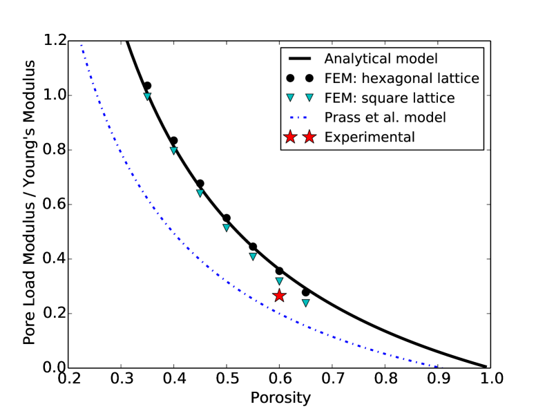
Comparison of the model to our experimental data (Fig. 4) shows that if we assume that the Young’s modulus of pSi walls equals to the bulk 100 value, the experimental data is close to the theoretical predictions, yet slightly below them. This deviation can be due to the irregularity of the pSi structure. Both the deviation of pore sizes from the mean size (i.e. PSD) and deviation of the pore arrangement from a perfect lattice lead to presence of thinner pore walls, which reduces the pore-load modulus of the structure. Also, the Young’s modulus of the walls can be somewhat lower than the modulus for bulk silicon; applying our model to calculate the Young’s modulus from our experimental value of , we get GPa. Note, however, that here the deviation of Young’s modulus of the pore walls from the Young’s modulus of bulk silicon is only 27% and not a factor of five as reported in Grosman et al. (2015).
The system of hexagonally-ordered parallel cylindrical pores is not unique to mesoporous silicon: a number of templated mesoporous materials have similar morphology, among them MCM-41 and SBA-15 silica, and silica monoliths with hierarchical pores, synthesized recently Balzer et al. (2015). The model for the pore-load modulus proposed in this work can be applied to develop quantitative models of adsorption-induced deformation of these materials. It should provide better predictions than the earlier model Prass et al. (2009) at porosities and below, typical for mesoporous silica.
To summarize, we have presented an experimental study of water adsorption-induced deformations of a monolithic, mesoporous silicon membrane, and extracted the pore-load modulus. We have proposed an analytical model which relates the pore-load modulus to the porosity and to the elastic properties of bulk silicon, and justified it by comparing with FEM simulations. We have found good agreement between our experimental data and the predictions of our model, with the Young’s modulus of the pore walls slightly lower than the bulk value for silicon. Our model can be applied to a large class of materials with morphologies similar to mesoporous silicon. Moreover, our findings suggest that liquid condensation experiments allow one to access the elastic constants of a mesoporous medium.
This research was performed while one of the authors (G.G.) held a National Research Council Research Associateship Award at Naval Research Laboratory. G.G. thanks John Michopoulos for insightful discussions of the FEM representation of the problem. The work of G.G. and N.B. was funded by the Office of Naval Research through the Naval Research Laboratory’s basic research program. P.H. acknowledges support by the German research foundation (DFG) within the collaborative research initiative “Tailor-made Multi-Scale Materials Systems” (SFB 986, project area B, Hamburg).
References
- Canham (1990) L. Canham, Appl. Phys. Lett. 57, 1046 (1990).
- Lehmann and Gösele (1991) V. Lehmann and U. Gösele, Appl. Phys. Lett. 58, 856 (1991).
- Sailor (2012) M. J. Sailor, Porous silicon in practice: preparation, characterization and applications (John Wiley & Sons, 2012).
- Canham (2015a) L. Canham, ed., Handbook of Porous Silicon (Springer, 2015a).
- Henstock et al. (2015) J. Henstock, L. Canham, and S. Anderson, Acta Biomater. 11, 17 (2015).
- Huber (2015) P. Huber, J. Phys.: Condens. Matter 27, 103102 (2015).
- Bellet et al. (1996) D. Bellet, P. Lamagnere, A. Vincent, and Y. Brechet, J. Appl. Phys. 80, 3772 (1996).
- Populaire et al. (2003) C. Populaire, B. Remaki, V. Lysenko, D. Barbier, H. Artmann, and T. Pannek, Appl. Phys. Lett. 83, 1370 (2003).
- Coasne et al. (2002) B. Coasne, A. Grosman, C. Ortega, and M. Simon, Phys. Rev. Lett. 88, 256102 (2002).
- Wallacher et al. (2004) D. Wallacher, N. Künzner, D. Kovalev, N. Knorr, and K. Knorr, Phys. Rev. Lett. 92, 195704 (2004).
- Hofmann et al. (2005) T. Hofmann, D. Wallacher, P. Huber, and K. Knorr, J. Low Temp. Phys. 140, 91 (2005).
- Naumov et al. (2008) S. Naumov, A. Khokhlov, R. Valiullin, J. Kärger, and P. A. Monson, Physical Review E 78, 060601 (2008).
- Kumar et al. (2008) P. Kumar, T. Hofmann, K. Knorr, P. Huber, P. Scheib, and P. Lemmens, J. Appl. Phys. 103, 024303 (2008).
- Henschel et al. (2009) A. Henschel, P. Kumar, T. Hofmann, K. Knorr, and P. Huber, Phys. Rev. B 79, 032601 (2009).
- Kärger and Valiullin (2014) J. Kärger and R. Valiullin, in Handbook of Porous Silicon, edited by L. Canham (Springer, 2014), pp. 1–10.
- Westover et al. (2014) A. S. Westover, J. W. Tian, S. Bernath, L. Oakes, R. Edwards, F. N. Shabab, S. Chatterjee, A. V. Anilkumar, and C. L. Pint, Nano Lett. 14, 3197 (2014).
- Gor and Neimark (2010) G. Y. Gor and A. V. Neimark, Langmuir 26, 13021 (2010).
- Amberg and McIntosh (1952) C. Amberg and R. McIntosh, Can. J. Chem. 30, 1012 (1952).
- Schappert and Pelster (2014) K. Schappert and R. Pelster, Langmuir 30, 14004 (2014).
- Günther et al. (2008) G. Günther, J. Prass, O. Paris, and M. Schoen, Phys. Rev. Lett. 101, 086104 (2008).
- Prass et al. (2009) J. Prass, D. Müter, P. Fratzl, and O. Paris, Appl. Phys. Lett. 95, 083121 (2009).
- Balzer et al. (2015) C. Balzer, R. Morak, M. Erko, C. Triantafillidis, N. Hüsing, G. Reichenauer, and O. Paris, Z. Phys. Chem. pp. DOI: 10.1515/zpch–2014–0542 (2015).
- Mogilnikov and Baklanov (2002) K. Mogilnikov and M. Baklanov, Electrochem. Solid-State Lett. 5, F29 (2002).
- Dourdain et al. (2008) S. Dourdain, D. Britton, H. Reichert, and A. Gibaud, Appl. Phys. Lett. 93, 183108 (2008).
- Reichenauer and Scherer (2001) G. Reichenauer and G. Scherer, J. Non-Cryst. Solids 285, 167 (2001).
- Herman et al. (2006) T. Herman, J. Day, and J. Beamish, Phys. Rev. B 73, 094127 (2006).
- Shao et al. (2010) L.-H. Shao, H.-J. Jin, R. N. Viswanath, and J. Weissmüller, EPL 89, 66001 (2010).
- Dolino et al. (1996) G. Dolino, D. Bellet, and C. Faivre, Phys. Rev. B 54, 17919 (1996).
- Bertinetti et al. (2013) L. Bertinetti, F. Fischer, and P. Fratzl, Phys. Rev. Lett. 111, 238001 (2013).
- Zhao et al. (2014) Q. Zhao, J. W. Dunlop, X. Qiu, F. Huang, Z. Zhang, J. Heyda, J. Dzubiella, M. Antonietti, and J. Yuan, Nat. Commun. 5 4293 (2014).
- Scherer (1986) G. W. Scherer, J. Am. Ceram. Soc. 69, 473 (1986).
- Gibson and Ashby (1999) L. J. Gibson and M. F. Ashby, Cellular Solids: Structure and Properties (Cambridge University Press, 1999).
- Grosman et al. (2015) A. Grosman, J. Puibasset, and E. Rolley, EPL (Europhysics Letters) 109, 56002 (2015).
- Landers et al. (2013) J. Landers, G. Y. Gor, and A. V. Neimark, Colloids Surf., A 437, 3 (2013).
- Gor et al. (2013) G. Y. Gor, O. Paris, J. Prass, P. A. Russo, M. M. L. Ribeiro Carrott, and A. V. Neimark, Langmuir 29, 8601 (2013).
- Gor (2014) G. Y. Gor, Langmuir 30, 13564 (2014).
- Canham (2015b) L. Canham, Handbook of Porous Silicon (Springer, 2015b), chap. Mechanical Properties of Porous Silicon, pp. 213–220.
- Magoariec and Danescu (2009) H. Magoariec and A. Danescu, Phys. Status Solidi C 6, 1680 (2009).
- Hecht (2012) F. Hecht, J. Numer. Math. 20, 251 (2012).
- Hopcroft et al. (2010) M. A. Hopcroft, W. D. Nix, and T. W. Kenny, J. Microelectromech. Syst. 19, 229 (2010).
- Timoshenko and Goodier (1970) S. Timoshenko and J. Goodier, Theory of Elasticity (McGraw-Hill, New York, 1970), 3rd ed.
- Landau and Lifshitz (1986) L. D. Landau and E. Lifshitz, Theory of Elasticity, vol. 7 of Course of Theoretical Physics (Elsevier, 1986), 3rd ed.