Multiferroic heterostructures for spin filter application - an ab initio study
Abstract
Novel imaging spin-filter techniques, which are based on low energy electron diffraction, are currently of high scientific interest. To improve the spin-detection efficiency a variety of new materials have been introduced in recent years. A new class of promising spin-filter materials are represented by multiferroic systems, as both magnetic and electric ordering exist in these materials. We have investigated Fe/BaTiO3(001), which defines a prominent candidate due to its moderate spontaneous polarization, for spin filter applications calculating diffraction patterns for spin polarized electrons incident on the Fe surface. Motivated by the fact that spin polarized low energy electron diffraction is a powerful method for the determination of the properties of surfaces we investigated the influence of switching the BaTiO3 polarization on the exchange and spin orbit scattering as well as on reflectivity and figure of merit. This system obviously offers the possibility to realize a multiferroic spin filter and manipulating the spin-orbit and exchange scattering by an external electric field. The calculations have been done for a large range of kinetic energies and polar angles of the diffracted electrons considering different numbers of Fe monolayers.
I Introduction
Materials combining different ferroic properties are called multiferroics schmidt1 . Multiferroic systems, especially multiferroic heterostructures, are promising in technical applications giving for example the opportunity to change the magnetization of a ferromagnetic material altering the electric polarization of a ferroelectric material or vice versa. An essential requirement of the realization of such systems was the development of experimental techniques over the last years for growing epitaxial magnetic and ferroelectric materials dawber1 ; zheng1 . Additionally a well-defined interface has to be ensured between both ferroic phases to enable an effective coupling. Various experimental groups investigated prototypical devices using external electric fields for a change of the ferroelectric polarization and investigated the influence on the magnetic properties of the ferromagnetic phase eerenstein1 . The application of such new systems are broad but especially as memory devices epitaxial thin films might be interesting ahn1 . Because of the technical applicability the discovery for new multiferroic materials with strong coupling between the ferromagnetic and the ferroelectric phases has been strengthen kimura1 ; lawes1 . The understanding of the coupling mechanism between both ferroic phases is essential for the development of multiferroic heterostructures and their technical application. Therefore different ferroelectric materials have been studied extensively in previous theoretical investigations where the BaTiO3 (BTO) takes a prominent position due to its moderate spontaneous polarization fechner1 .
For the construction of a multi-channel vector spin polarimeter at BESSY II new types of material classes are tested for their applicability as reflecting mirror for spin polarized electrons. Beside well tested materials likewise W, Ir, and oxygen passivated Fe other material classes should be investigated yielding interesting properties for spin filter purposes. Because of the high magnetic moments for the Fe layers of Fe/BTO and the dependency of their magnitude on the BTO polarization fechner2 ; borek1 this heterogeneous system is an interesting candidate for the application as spin polarizing mirror. In principle using a multiferroic heterostructure would give the possibility to alter the exchange and spin-orbit scattering switching the electrical polarization of the BTO. Thereby no additional magnetic field is necessary for changing the surface magnetization of the ferromagnetic material. Especially working areas inducing an altering of the scattered spin direction by switching the BTO polarization are interesting for an application as spin polarizing mirror.
In this work we studied the scattering of spin polarized electrons from the surface of the multiferroic heterostructure Fe/BTO. We calculated diffraction patterns visualizing the dependency of the scattered intensity on the polar angles and kinetic energies. Because the polarization of the electrons were oriented perpendicular to the scattering plane, both exchange and spin-orbit scattering occur feder1 ; tamura1 . Therefore we investigated the so-called exchange and spin-orbit asymmetries as well as the effective reflectivity and the figure of merit (FOM). Additionally we investigated the layer dependence of the exchange and spin-orbit scattering. We applied SPLEED (Spin Polarized Low Energy Electron Diffraction) calculations to 1, 2 and 3 monolayer (ML) Fe on top of BTO because their applicability as multiferroic system has been mentioned and their electronic and magnetic structure was investigated in detail in previous works fechner2 ; meyerheim1 . For all systems the crystal structure was taken from previous investigations providing a relaxed interface and surface fechner2 . This accounts for the fact that SPLEED is very surface sensitive due to the low kinetic energies of the incident electrons. For the calculation of the electronic properties and the electron diffraction we applied the fully relativistic KKR-method in the framework of spin-polarized density functional theory to account for effects based on exchange and spin-orbit interactions in one step ebert1 ; SPR-KKR6.3 .
II Theoretical application
We briefly introduce the theoretical method implemented in the SPR-KKR program package for the calculation of spin-polarized electron scattering from arbitrary surface systems. The SPLEED calculations are done using the layered-KKR method feder2 . This method describes the scattering of spin polarized electrons from a stack of atomic layers representing a semi-infinite surface system. The two main steps are the treatment of multiple scattering within one specific atomic layer and the scattering between the atomic layers of the stack. The combination of both scattering mechanisms result in the calculation of the so-called bulk reflection matrix. With the determination of the bulk reflection matrix the diffraction of spin-polarized electrons from a surface is defined feder1 ; feder2 . Considering exchange and spin-orbit scattering there exist mainly two configurations according to the orientation of magnetization and polarization of the electron with respect to the scattering plane. Whereby the scattering plane is spanned by the wave vector of the incident electron and the scattered electron (see Fig. 1). In our calculations both surface magnetization and polarization of the electron are oriented perpendicular to the scattering plane. Therefore exchange and spin-orbit scattering contribute tamura1 .
The calculation of the scattered electron intensity was done for all combinations of magnetization and polarization, i.e. one ends up with four different intensities () feder1 ; tamura1 . Here is the magnetization direction and gives the polarization direction of the electron. From the reflected intensities the exchange asymmetry, spin-orbit asymmetry and FOM are calculated. The spin-orbit asymmetry can be determined via the relation feder1
| (1) |
which can be ascribed to the reflected intensities using the definitions
| (2) | |||
| (3) |
The exchange scattering for a specified magnetization direction is defined as and .
The most important quantity for the characterization of the diffraction of electrons from a surface is the FOM. The reflectivity as well as the asymmetry (exchange or spin-orbit) contribute to this quantity via the following equation
| (4) |
In Eq. (4) the FOM is calculated separately for the two specific magnetization directions. This gives insight into changes of the scattering behaviour changing the magnetization direction at the surface. The spin orbit induced FOM is defined by
| (5) |
with the effective reflectivity
| (6) |
For the calculation of SPLEED patterns it is necessary to determine the single site scattering matrix for the individual atomic types involved in the half-space of Fe/BTO. The self-consistent potentials necessary for calculating the single-site scattering matrices were taken from previous works fechner2 ; borek1 . With the single site-scattering matrix we were able to calculate the Kambe X-matrix and the bulk reflection matrix as described above.
Considering the escape of the diffracted electrons into vacuum an essential quantity for SPLEED is the work function and the surface potential barrier. For the work function we applied 4.7 eV which is a reasonable value for Fe(001) skriver1 whereas the surface potential barrier was simulated by the Rundgren-Malmström parametrization rundgren1 . We calculated SPLEED patterns for a broad range of kinetic energies and polar angles according to the working areas as scattering mirror. The calculations were done for the specular reflected beam and for the polarization of the BTO pointing in the direction of the surface normal (Pup) and to the opposite direction (Pdown).
In Fig. 1 the side view and top view of the Fe/BTO heterostructure are shown. Here 3 ML Fe are placed on top of the substrate BTO. The unit cell of BTO corresponds to a tetragonal distorted structure (P4mm) with a lattice parameter of 3.943 Åfechner3 . The structural details have been published in previous works fechner2 ; borek1 .
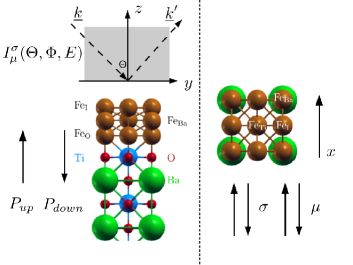
Remarkably the surface of the BTO has a (001) orientation and is terminated by O and Ti. The termination of the Fe/BTO system has been investigated in previous experimental studies MKE+11 . The multiferroic heterostructure was simulated by setting up a half-space of four unit cells of BTO for the transition from the surface to the bulk. From the fifth unit cell on the bulk region was started. Due to the distorted unit cell of BTO (P4mmm) a remanent electrical polarization occurs. This result from a shift of the Ti atom and the O atoms in opposite direction and generates the ferroelectric properties of BTO borek1 . It has been shown that the first Fe layer (FeO) on top of BTO is positioned on top of the O atoms. The second Fe layer has two inequivalent Fe sites which are on top of Ti (FeTi) and Ba (FeBa). The third Fe layer (FeI) is placed on top of the Fe atoms of the first Fe layer fechner2 . The surface as well as the interface of the multiferroic heterostructure has been relaxed in previous works fechner2 using the Vienna Ab initio Simulation Package (VASP) KF96 ; KJ99 . The resulting structure parameters have been presented and discussed fechner2 . Using the relaxed crystal structure we applied the fully relativistic multiple scattering formalism for the calculation of the SPLEED patterns as sketched above SPR-KKR6.3 . The self-consistent calculation of the system potentials has been done using a previously multicode approach borek1 ; LET+01 ; Ebert96 .
III Results and Discussion
The results of the electronic structure calculations, especially the spin magnetic moments have shown to be in good agreement with published data fechner2 ; borek1 . The magnetic properties of the Fe surface are most important for the exchange scattering of spin-polarized electrons. Changing the polarization of the BTO affects the magnetic moments of the Fe layers. Therefore the surface magnetic moments have shown to react on a competition of the reduced number of nearest neighbors at the surface and hybridization effects between the Fe and O states as well as the Fe and Ti states DSM+06 ; fechner1 ; fechner2 . The impact on the electronic structure has been investigated in detailed studies fechner2 . It was shown that for 1 ML Fe on top of BTO a ferromagnetic ground state occurs with a large spin magnetic moment for Fe due to the reduced coordination number at the surface. For 2 ML Fe on BTO a ferrimagnetic ground state was predicted whereas the Fe atoms in the second Fe layer (FeTi, FeBa) show an antiparallel alignment of their spin directions and different magnitudes. For 3 ML Fe a ferromagnetic ground state was predicted. The change of the BTO polarization affects the spin magnetic moments of Fe via a change in the hybridization of the Fe, Ti and O states mentioned above. A smaller (larger) hybridization of the states of Fe - Ti and the states of O results in a larger (smaller) spin magnetic moment of Fe borek1 . Therefore the magnetoelectric coupling between the ferroelectric and ferromagnetic material is based on hybridization effects fechner2 . The change of the magnetic properties has an influence on the optical properties like the absorptive part of the conductivity tensor borek1 and are detectable using the scattering of electrons with low kinetic energy, as will be shown below.
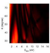
In Fig. 2 the reflectivity for 3 ML Fe/BTO for a [100] surface magnetization is shown.
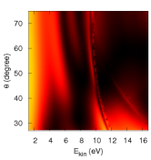
The range of polar angles and kinetic energies have been chosen according to a possible application as scattering mirror thiede1 . The diffraction pattern can be divided into two main parts with respect to the kinetic energy. The main differences occur for kinetic energies 8 eV, i.e. below the emergence threshold. The emergence threshold marks the occurrence of an additional beam lowering the intensity of the specular diffracted one. The area of high reflectivity for kinetic energies at 4 eV covers nearly the total range of polar angles. This is important for later application as scattering mirror giving the possibility to vary the position of the mirror with respect to the polar angle of the incident electrons. For kinetic energies lower the emergence threshold a large sensitivity changing the BTO polarization is visible. On the other hand for kinetic energies above the emergence threshold switching the BTO polarization has less influence on the reflectivity. This is due to the fact that electrons with lower kinetic energy react more sensitive on changes of the surface magnetization, i.e. onto variations of the exchange and spin-orbit scattering. For kinetic energies above 10 eV an area of high reflectivity is visible for polar angles around 30∘. Because of the high kinetic energy this area is much less affected by a change of the BTO polarization.
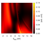
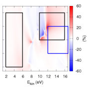
In Fig. 3 the exchange asymmetries for 3 ML Fe/BTO for both BTO polarizations are shown with an [100] magnetization direction of the surface. For the investigated range of polar angles and kinetic energies two areas (marked by black rectangles) occur with a large variation of the exchange scattering.

The first area is located at lower kinetic energies of the incident electrons ( 6 eV) the second area at higher kinetic energies (12-17 eV). The different colors in the diffraction patterns indicate a change of the alignment of electron polarization and surface magnetization. Whereas the red color correspond to a parallel alignment of polarization and magnetization the blue color correspond to an antiparallel alignment. As shown in Fig. 3 changing the BTO polarization from Pup to Pdown changes the reflected spin polarization in the marked areas. Especially for the area at lower kinetic energy and higher polar angle, which provides high reflectivity, a change of the reflected spin direction due to a change of the BTO polarization is possible.
In Fig. 3 the exchange scattering for both polarization directions of the BTO for a magnetization in direction is shown in addition. In comparison to a magnetization direction pointing in the direction a less pronounced change in the exchange scattering occurs especially for higher kinetic energies. This results from spin-orbit scattering caused by the fact that for a scattering configuration with vanishing spin-orbit interaction holds tamura1 , i.e. the exchange asymmetries for both magnetization directions are indistinguishable.
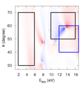
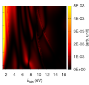
The spin-orbit induced contribution to the specular scattering of the electrons is shown in Fig. 4. Marked by black rectangles the spin-orbit asymmetry shows a higher change by switching the BTO polarization. These areas coincide with the rectangles for the exchange asymmetry for a direction of the magnetization. The blue rectangles correspond to an exchange asymmetry for the direction. According to the specified areas of the exchange asymmetry the blue rectangles show a minor change of the spin-orbit asymmetry and therefore a minor change in the exchange asymmetry (see Fig. 3). This results in a more sensitive reaction of the exchange asymmetry on a change of the BTO polarization using a orientation of the magnetization. This is important for the use as spin polarizing mirror indicating that an orientation of the surface magnetization would be preferable along the direction.
The lowering of the reflectivity affects the FOM via Eq. (4). The exchange asymmetry enters Eq. (4) to the power of two and therefore dominantly determines the FOM. This is the reason for the correspondence of areas of high exchange scattering and FOM. In Fig. 5 the FOM for both BTO polarization directions are shown.
The FOM shows significant changes for kinetic energies 6 eV. Therefore the multiferroic heterostructure 3 ML Fe/BTO would have most promising technical applicability for VSPLEED experiments. With respect to the area of high FOM around 4 eV for an polarization of the BTO oriented along the surface normal the system Fe/BTO could be used as switch for the electron spin directions. Changing the BTO polarization the value of the FOM drops drastically, i.e. no electrons are reflected.
In comparison to investigations done for an oxygen passivated Fe surface thiede1 ; BBM+15 the reflectivity is in the same order whereas the FOM is an order of magnitude lower for the multiferroic heterostructure. Therefore the spin resolving power is less for the Fe/BTO system lowering its applicability as spin-polarizing mirror. Because it is know that Fe(001)-p(1x1)-O has a longer lifetime in vacuum and additionally a higher FOM BOC99 in comparison to a Fe(001) surface it would be interesting to investigate the effect of an O overlayer on top of Fe/BTO which will be investigated in a later work.
III.1 Layer dependence of SPLEED
In addition we investigated the change of the electron scattering for thinner Fe layers (1 ML, 2 ML) on top of BTO. The structural properties correspond to systems studied in previous works fechner2 . The results of our calculations have shown that the most pronounced changes of the exchange asymmetry by changing the polarization of the BTO occur for 3 ML Fe/BTO. Therefore the results for 1 ML and 2 ML will not be shown in detail here. Nevertheless, the scattering patterns for 1 ML and 2 ML reveal differences between both BTO polarizations corresponding to 3 ML Fe/BTO. The differences in the exchange scattering between 1 ML, 2 ML and 3 ML Fe/BTO can be related to the changes of the in plane spin magnetic moments changing the polarization of the BTO. In Table 1 the changes of the in plane spin magnetic moments for a change of the BTO polarization are listed for the several Fe layers. The largest change of the spin moments occur for the topmost Fe layer of 3 ML Fe/BTO. Therefore an electron impinging on the surface interacting mainly with the topmost Fe layer would adept the largest change of the exchange scattering for 3 ML Fe/BTO. For 1 ML and 2 ML Fe/BTO the changes are smaller resulting in a less pronounced change of the exchange scattering.
| 1 ML | 2 ML | 3 ML | |
| FeI | -0.18 | ||
| FeTi+FeBa | -0.08 | 0.04 | |
| FeO | -0.02 | 0.0 | 0.2 |
IV Summary
Using an ab initio formalism we calculated SPLEED patterns for 1, 2 and 3 ML Fe/BTO. We investigated the change of the reflectivity, the FOM and both exchange and spin-orbit asymmetry changing the polarization of BTO. We showed that the largest differences of the diffraction patterns by changing the electric polarization of BTO results for 3 ML Fe/BTO. We located two areas in the diffraction patterns for which a change of the BTO polarization induces a significant change of the exchange asymmetry. Therefore a combination of a ferroelectric and a ferromagnetic material would enable new applications for spin filter purposes, according to the working areas especially for VSPLEED experiments. For higher kinetic energies the Fe/BTO system has a smaller FOM compared to the intensively studied Fe(001)-p(1x1)-O surface. Therefore investigating the impact of an additional O layer on top of Fe will be done in the near future.
V Acknowledgement
We thank the BMBF (05K13WMA), the DFG (FOR 1346), CENTEM PLUS (LO1402), CENTEM (CZ.1.05/2.1.00/03.0088) and the COST Action MP 1306 for financial support.
References
- (1) H. Schmidt, Ferroelectrics 162, 317 (1994).
- (2) M. Dawber, K. M. Rabe, and J. F. Scott, Phys. Rev. B 77, 094112 (2008).
- (3) H. Zheng et al., Science 303, 661 (2004).
- (4) W. Eerenstein, N. D. Mathur, and J. F. Scott, Nature 442, 759 (2006).
- (5) C. H. Ahn, K. M. Rabe, and J.-M. Triscone, Science 303, 488 (2004).
- (6) T. Kimura, Nature 426, 55 (2003).
- (7) G. Lawes, Phys. Rev. Lett. 95, 087205 (2005).
- (8) M. Fechner, S. Ostanin, and I. Mertig, Phys. Rev. B 77, 094112 (2008).
- (9) M. Fechner et al., Phys. Rev. B 78, 212406 (2008).
- (10) S. Borek et al., Phys. Rev. B 85, 134432 (2013).
- (11) R. Feder, J. Phys. C: Solid State Phys. 14, 2049 (1981).
- (12) E. Tamura, B. Ackermann, and R. Feder, J. Phys. C: Solid State Phys. 17, 5455 (1984).
- (13) H. L. Meyerheim et al., Phys. Rev. Lett. 106, 087203 (2011).
- (14) H. Ebert, D. Ködderitzsch, and J. Minár, Rep. Prog. Phys. 74, 096501 (2011).
- (15) H. Ebert et al., The Munich SPR-KKR package, version 6.3,H. Ebert et al. http://olymp.cup.uni-muenchen.de/ak/ebert/SPRKKR, 2012.
- (16) R. Feder, Principles and theory of electron scattering and photoemission, in Polarized Electrons in Surface Physics, World Scientific, 1985.
- (17) H. L. Skriver and N. M. Rosengaard, Phys. Rev. B 45, 9410 (1992).
- (18) J. Rundgren and G. Malmström, J. Phys. C: Solid State Phys. 10, 4671 (1977).
- (19) M. Fechner, S. Ostanin, and I. Mertig, Phys. Rev. B 80, 094405 (2009).
- (20) H. L. Meyerheim et al., Phys. Rev. Lett. 106, 087203 (2011).
- (21) G. Kresse and J. Furthmüller, Phys. Rev. B 54, 11169 (1996).
- (22) G. Kresse and D. Joubert, Phys. Rev. B 59, 1758 (1999).
- (23) M. Lüders, A. Ernst, W. M. Temmerman, Z. Szotek, and P. J. Durham, Journal of Physics: Condensed Matter 13, 8587 (2001).
- (24) H. Ebert, Reports on Progress in Physics 59, 1665 (1996).
- (25) C.-G. Duan, R. F. Sabirianov, W.-N. Mei, S. S. Jaswal, and E. Y. Tsymbal, Nano Letters 6, 483 (2006).
- (26) C. Thiede et al., Phys. Rev. Appl. 1, 054003 (2014).
- (27) S. Borek, J. Braun, J. Minár, and H. Ebert, arXiv:1504.08198 (2015).
- (28) R. Bertacco, D. Onofrio, and F. Ciccacci, Review of Scientific Instruments 70, 3572 (1999).