Theory of spin Hall magnetoresistance (SMR) and related phenomena
Abstract
We review the so-called spin Hall magnetoresistance (SMR) in bilayers of a magnetic insulator and a metal, in which spin currents are generated in the normal metal by the spin Hall effect. The associated angular momentum transfer to the ferromagnetic layer and thereby the electrical resistance is modulated by the angle between the applied current and the magnetization direction. The SMR provides a convenient tool to non-invasively measure the magnetization direction and spin-transfer torque to an insulator. We introduce the minimal theoretical instruments to calculate the SMR, i.e. spin diffusion theory and quantum mechanical boundary conditions. This leads to a small set of parameters that can be fitted to experiments. We discuss the limitations of the theory as well as alternative mechanisms such as the ferromagnetic proximity effect and Rashba spin-orbit torques, and point out new developments.
Keywords: spintronics, spin currents, spin Hall effect
1 Introduction and motivation
Spintronics invokes the spin degree of freedom of the electron to improve the efficiency of and add functionalities to electronic devices [1, 2]. Here the generation, propagation, processing, and detection of spin currents form central themes [3]. The spin-orbit coupling (SOC) provides a mechanism to couple the charge and spin of electrons. A prominent example is the spin Hall effect (SHE), i.e. the SOC-induced pure spin current transverse to an applied charge current [4, 5, 6]. In bilayers of a normal metal (N: a non-magnetically ordered metal) and a ferromagnet (F, which includes “ferrimagnet” in the present context), the magnetization dynamics is affected by the SHE spin current via the spin-transfer torque [7] that can be strong enough to switch the magnetization [8, 9]. On the other hand, the inverse of the SHE (ISHE), i.e., the pure spin current-driven transverse charge current, is a convenient tool to detect spin currents generated by spin pumping (SP) [10, 11, 12, 13] and the spin Seebeck effect (SSE) [14, 15, 16, 17, 18]. Quite some attention has been recently focused on ferromagnetic insulators (FI) such as yttrium iron garnet (YIG: Y3Fe5O12) that can be activated electrically and thermally by attached normal metal contacts. YIG’s very low magnetization damping makes it an attractive material for low-power spin-wave based interconnects and heat-harvesting devices [19].
The magnetoresistance (MR) is the ratio of the electrical resistance of a material with and without an applied magnetic field [20]. In ferromagnetic conductors the MR is often dominated by effects that are not caused directly by the applied magnetic field, but rather by the magnetization orientation as controlled by the applied field. The anisotropic magnetoresistance (AMR), for example, refers to the phenomenon that the electrical resistance of ferromagnets depends on the angle between the current and magnetization directions [21, 22, 23]. For applications in magnetic field sensors and data storage devices, the AMR has been superseded by the giant magnetoresistance (GMR) [24] and tunneling magnetoresistance [25, 26].
This review addresses a new type of MR discovered in a bilayer made of a metal N with strong SOC (usually platinum) and an FI (usually YIG), where the electrical resistance was found to depend on the magnetization of the FI [17, 27, 28, 29, 30, 31]. Since it can be explained by the simultaneous action of the SHE and ISHE [32], it has been dubbed spin Hall magnetoresistance (SMR). This mechanism is similar to that of the predicted magnetoresistance of the two-dimensional electron gas induced by magnetic field-induced decoherence of an edge spin accumulation [33] (the related “Hanle effect” was observed recently in Pt films under large magnetic fields [34]). The SMR can be used to electrically measure the magnetization direction of an insulator [35] and helps to non-invasively access fundamental transport parameters such as the spin Hall angle, spin diffusion length, and spin-transfer torque (spin-mixing conductance) at an NFI interface [36].
The SMR originates from the simultaneous action of two effects, viz. the SHE and ISHE, that both made an impact on modern spintronics. The SHE causes current-induced spin-transfer torques without a polarizing ferromagnet (“spin-orbit torques”) while the ISHE has become a standard method of detecting spin currents. However, controversial issues remain, such as the magnetic proximity effect and the Rashba SOC at the NFI interface, challenging the applications mentioned above, but also our understanding of phenomena such as the spin Seebeck effect. The SMR in NFI bilayers is arguably the most simple observable to detect SOCs: It exists in bilayers of well-studied and characterized materials, and is a strictly linear response effect. Hence, it is essential to understand the SMR before more complicated ones that involve complex devices, difficult materials, magnetization dynamics, noise or non-linearitis. Many groups have theoretically and experimentally studied the SMR since its discovery. Hence we believe that the time has come to consolidate the existing knowledge.
This review is organized as follows: In section 2, we introduce the basic concepts and prevalent materials necessary to understand and observe the SMR. In section 3, we describe the diffusion theory for the (I)SHE with quantum mechanical boundary conditions at interfaces. Experiments by various groups are discussed in section 4 as well as the parameters obtained by fitting the theory. In section 5, we address controversial issues such as magnetic proximity and Rashba SOC at interfaces. SMR-related new developments are reviewed in section 6. We present conclusions and an outlook in section 7.
2 Materials and devices
In this chapter we review briefly pertinent basic notions in spintronics and magnetism that are used in the subsequent discussions. It starts with metallic ferromagnets that have been subject of transport studies for almost two centuries. Phenomena driven by the SOC in metallic ferromagnets such as the anisotropic magnetoresistance (AMR) and the anomalous Hall effect (AHE) are still not fully understood. The spin Hall effect, i.e. the analogue of the AHE in nonmagnetic metals, has a much shorter history. Its potential to convert the flows of charge and spin has inspired the whole spintronics community. Multilayers made of metallic ferromagnets and nonmagnetic metals are known to display the GMR and TMR as well as spin-transfer torques mediated by the exchange interaction. More recently, SOC induced spin-transfer torques have been the center of interest. Here we introduce a few of these notions as background to the system and phenomenon of interest, i.e. the SMR in NFI bilayers.
2.1 Metallic ferromagnets, AMR and AHE
Metallic ferromagnets, especially the transitions metals and their alloys, are important in magnetoelectronics due to their high conductivities and Curie temperatures. Their magnetization is therefore ideal for non-volatile information storage and electrical readout. The band structure in a ferromagnet is spin-dependent, as are its transport properties that are well described by a two parallel current model for majority and minority spins. Introducing the spin-dependent conductivity (), an electric field induces the charge current
| (1) |
where is the total conductivity. An applied charge current is accompanied by a spin current [37]
| (2) |
with conductance spin polarization
| (3) |
The spin dependence of transport is not easily observed in bulk ferromagnets directly. The “ordinary” magnetoresistance, i.e. the dependence of the electrical resistance on an applied magnetic field exists even for normal metals without SOC through the Lorentz force [20]. The AMR, i.e. the phenomenon that the electric resistance depends on the angle between the electric current and the magnetization vectors, is observed in metallic ferromagnets [21, 22]. When current and magnetization direction are given by unit vectors and , the electric resistance in an isotropic (or cubic) material reads
| (4) |
where with () the resistivity for magnetization parallel (transverse) to the applied current, and is an averaged value over all directions for which different definitions can be found in the literature, for example, as [22]. A corollary of the AMR is the transverse resistivity also referred to as planar Hall effect. With current direction along
| (5) | |||||
| (6) |
where is the Cartesian -component of the magnetization direction unit vector. Higher order contributions to the AMR are found in single-crystalline thin films [39]. From the theoretical point of view, can be derived microscopically from the - model with a free -electron conduction band and localized -electrons with a strong exchange interaction and weak SOC. In this model, transport is carried by the conduction electrons with a contribution to the resistivity from scattering into localized -states by impurities that depends on the magnetization direction owing to the SOC. The AMR has been of considerable interest as a tool to measure the magnetization direction electrically, thereby serving as a magnetic field sensor [22]. It still attracts scientific attention nowadays [40], and new regimes are being opened by studies in ultrathin films [41, 42, 43].
The “ordinary” Hall effect refers to the transverse charge current normal to both an applied current and external magnetic field and is named after its discoverer [44]. The AHE, found by Hall two years later [38], depends neither on the external magnetic field nor on the internal dipolar field, but is caused by the SOC or magnetic orientational disorder (which is generated by SOC) [45]. Phenomenologically,
| (7) |
where is the applied charge current density and is the anomalous Hall angle, i.e. the ratio between the transverse and longitudinal conductivities or the slope in plots of the anomalous Hall conductivity as a function of the longitudinal one. Controversies about the microscopic mechanism of the AHE, e.g. whether it is intrinsic or extrinsic, linger, but it appears to be generally accepted that the extrinsic skew scattering process dominates in the clean regime, while intrinsic band structure effects and/or extrinsic side jump scattering explain results for moderately good metals [45, 46, 47]. The anomalous Hall effect can be interpreted in terms of the spin Hall effect discussed hereafter: In ferromagnets a spin polarized current is converted into a transverse charge current or voltage by the spin-dependent conductances as parameterized by the polarization .
2.2 Spin Hall effect and its inverse in normal metals
In normal metals without magnetic order, electrons with spin up and spin down are degenerate and contribute to transport as two channels in parallel. Nevertheless, significant SOC causes an analogue of the AHE known as the spin Hall effect (SHE), by which a charge current generates a pure transverse spin current, i.e., a current of spin angular momentum [4, 6]. While a spin accumulation can be detected by optical methods at lease in some systems [48], we are not aware of experiments that can measure a spin current directly. However, Onsager reciprocity demands that an inverse SHE (ISHE) exists, implying that a spin current drives an easily detectable transverse charge current or voltage [49, 50].
The SHE and ISHE can be described by
| (8) | |||||
| (9) |
Here is the direction vector of an SHE spin current density polarized along with modulus . It is driven by the applied charge current density and proportional to the spin Hall angle . is the charge current driven by an -polarized spin current in direction. Note that we define spin currents in units of Ampere; they can be converted to angular momentum currents by the factor .
2.3 Metallic multilayers and spin-transfer torques
Modern crystal growth techniques allow controlled fabrication of multilayers from various materials with individual film thicknesses of only a few monolayers. This led to the discovery of the giant magnetoresistance (GMR) in the current-in-plane (CIP) configuration, i.e., the difference of electric conductivity between parallel and anti-parallel (magnetic) configurations in the layered structures [51, 52]. This effect has been explained by the spin-dependent scattering of electrons at NF interfaces: in the anti-parallel configuration both spin species are scattered strongly at opposite interfaces. When an applied magnetic field forces a parallel configuration one spin channel is short-circuited, leading to a reduced resistance [53].
The GMR in the current perpendicular to plane (CPP) configuration is often larger [54, 55, 56] and easy to model by one-dimensional spin diffusion theory [57]. The essential quantity is here the distributed difference between the effective chemical potentials of electrons with opposite spins or “spin accumulation”. The transfer of spin angular momentum between magnetic layers by an applied current, i.e., the spin-transfer torque, was predicted [58, 59] and observed [60, 61, 62, 63] in CPP spin valve structures. Magnetoelectronic circuit theory for magnetic heterostructures with non-collinear magnetizations provides a theoretical basis to understand the material dependence of these effects [64]. By scattering theory, the spin current through an NF interface (on the N side, flowing into F) can be expressed in terms of the F magnetization and the (vector) spin accumulation in N:
| (10) |
where is the charge of an electron, and
| (11) | |||
| (12) |
are the flows of electrons with spin-up and down electrons along driven by the difference between effective charge chemical potentials in N and F () and the difference between spin accumulations at both sides of the interface (). The charge and spin chemical potentials are related to each other as discussed in section 3.1, while the spin-dependent conductances at the interface read
| (13) | |||
| (14) |
where is the spin up (down) reflection coefficient of an electron at the NF interface from transport channel to channel in N. Here is the (single-spin) conductance quantum.
The last two terms in (10) are spin currents transverse to the magnetization and parameterized by the spin-mixing conductance at the interface defined by the elements of the spin-dependent scattering matrix
| (15) |
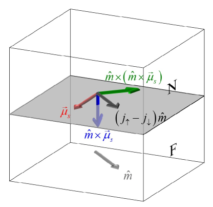
Figure 1 illustrates the spin current polarizations at the interface expressed in (10). The part of the spin current with spin polarization along the magnetization orientation in F component [] can flow in a metallic F, while the transverse components [ and ] are absorbed at the interface on an (for strong ferromagnets) atomic length scale and therefore acts as a torque on the magnetization. The spin-transfer torque at the interface is obtained from by projection
| (16) |
(10) can be used stand-alone for tunnel junctions or point contacts, or serve as a boundary condition between bulk materials described by diffusion theory.
2.4 Spin-orbit torques
Electron and spin transport in NF bilayers in the current-in-plane (CIP) configuration attracted attention recently because of the observed large current-induced spin-transfer torques generated by the SOC [65]. Those spin-orbit torques can result from the spin currents generated by the SHE in the N layer [4, 5, 6], and converted to a magnetization torque by the conventional exchange interaction at the interface. This contributes a so-called “damping-like”torque proportional to with symmetry identical to the exchange-mediated term. The magnetic (Gilbert) damping in NF bilayers subject to an in-plane electric current is modulated by the spin-transfer torque in (16) generated by the direct SHE [7]. While the SHE generates spin currents, the ISHE in a normal metal is an efficient detector of spin currents generated, e.g., by spin pumping [10, 11, 12, 13] or the spin Seebeck effect [16]. On the other hand, a Rashba-Edelstein effect at the interface may generate a spin accumulation that acts directly on the magnetization to exert a “field-like” torque, corresponding to a finite [66, 67, 68, 65]. The torque on the magnetization induced by the SOC can be strong enough to switch the magnetization [8, 9], with potential applications in magnetic storage technology. (10) may still be used for the boundary condition of SOC-generated spin currents at NF(I) interface [69], but the parameters might differ from their exchange-only values.
2.5 Magnetic insulators
In conventional spintronic devices such as spin valves, metallic ferromagnets serve as spin emitter (detector) to inject (absorb) spin current into (from) an adjacent normal metal. The spin transport in this CPP configuration requires charge flow through the ferromagnet that therefore has to be a metal. Recently, ferromagnetic insulators such as yttrium iron garnet (YIG) attracted attention of spintronics researchers [19]. Insulators can obviously not be used for voltage induced CPP charge flow, but importantly simplify interpretation in the CIP configuration because parallel charge transport channels through the magnet do not exist. Ferromagnetic insulators can have a much better magnetic quality than metals. YIG in particular features ultralow magnetization damping, which makes it attractive for various applications [19].
NF bilayers with an insulating ferromagnet F can be activated electrically by means of the SHE [70, 71], while the ISHE can be used to detect magnetization dynamics [10, 70, 72]. While electrical charge transport is suppressed in the CPP configuration, the thermal activation by a temperature gradient normal to the interface is possible. A temperature difference at the NF interface generates a spin current that can be detected by the ISHE in N without complications of parallel transport in the ferromagnet driven by e.g. the anomalous Nernst effect. This phenomenon is called (longitudinal) spin Seebeck effect [16] and its reciprocal is the spin Peltier effect [73]. The theory of the spin Seebeck effect is based on the concepts of thermal spin pumping and spin-transfer torques in which the spin-mixing conductance and spin Hall angle are essential parameters [74, 75].
3 Theory
In the following we derive in some detail the minimum model for the SMR, closely following Chen et al. [32].
3.1 Diffusion theory with spin-flip relaxation but without (I)SHE
Our theory of the SMR is based on a spin diffusion theory in the limit of weak SOC. We address the diffusion theories for both ferromagnetic and normal metals, in which the charge and spin currents are expressed in terms of gradients of charge and spin accumulations (or spin-dependent electrochemical potentials and densities). The charge current density is the expectation value of the current operator in terms of electron charge , the electrons density , and the velocity operator . For a normal metal with constant density and drift velocity ,
| (17) |
The spin current in the non-relativistic limit
| (18) |
is a second-order tensor, where is the vector of Pauli spin matrices, and denotes an expectation value. The row vectors in (18) are the spin current densities polarized in the -direction, while the column vectors denote the spin current densities with polarization flowing in the -direction. In metallic ferromagnets with homogenous texture, the average spin current is projected along the unit vector of the magnetization direction , so the charge current and spin current tensor read
| (19) | |||||
| (20) |
where is the spin current density direction vector, “” denotes that the polarization is locked along , and and are the spin-dependent electron density and drift velocity of majority/minority spins in the simple Stoner model. In contrast to the charge current, the (particle) spin current is not conserved in the presence of SOC and non-collinear magnetizations, leading to spin-transfer to the lattice or magnetization, respectively.
In heterostructures, it is useful to express currents in terms of (gradients of) local quasi-equilibrium thermodynamic parameters such as the (electro)chemical potential [76, 57, 77]. At temperatures well below the magnetic phase transition, transport in ferromagnetic metals is well described by the two-current model [37, 78]. The spin-dependent electrochemical potentials are denoted as :
| (21) |
where represents the spin direction (anti-)parallel to the magnetization in the ferromagnet, and the gradient is the external electric field. As discussed in section 2.1, the conductivity in ferromagnets is spin-dependent and denoted as . Thus we expect that close to contacts, , leading to spin-dependent diffusion currents
| (22) |
The charge and spin currents now read
| (23) | |||||
| (24) |
and polarization along is presumed. Correspondingly, the charge and spin electrochemical potentials are defined
| (25) | |||||
| (26) |
With these conventions, we may write Ohm’s law in the ferromagnetic metal
| (33) |
In a ferromagnet an applied electric field and/or a spin accumulation gradient generate a charge current as well as a spin current. The charge and spin electrochemical potentials can be obtained by solving the diffusion equations [57].
| (34) | |||
| (35) |
where the spin-flip diffusion length is expressed in terms of the spin-diffusion length for each spin . The spin-dependent charge diffusion constant depends on the spin-dependent relaxation time and Fermi velocity, and is the spin-dependent spin-flip time. With boundary conditions at contacts, interface and/or deep in the bulk materials, we may compute and , from which charge and spin currents are known by (33).
In normal metals, the electronic structure is spin-degenerate, but spin accumulations and spin currents can be injected by ferromagnetic contacts or generated via the SHE. The induced spin accumulations is represented by the (position dependent) vector
| (36) |
where represents the -th Cartesian component. The charge and spin accumulations obey the diffusion equations
| (37) | |||||
| (38) |
In the absence of the SHE, charge and spin currents are governed by Fick’s laws [20]
| (39) | |||||
| (40) |
The difference of the diffusion theory for normal metals with that of ferromagnets is the arbitrary direction of the spin polarization and the decoupling between spin and charge when
3.2 Interface boundary conditions
Solution of the diffusion equations requires boundary conditions for the currents at surfaces and/or interfaces. Here we disregard interfacial SOC and proximity effects. This approximation cannot be justified a priori, but first-principles calculations on NPyN sandwiches [Py: Permalloy (Ni80Fe20)] [79, 80] can be described by introducing effective spin-mixing conductances modified by the SOC.
In NFI bilayers charge currents flow in the metal layer parallel to the applied electric field. The spin currents driven by the SHE generate a spin accumulation at the interface that in turn induces a spin current [64]
| (41) |
where () is the real (imaginary) part of the spin-mixing conductance defined by (15). At the NFI interface, the reflection coefficients with modulus one and phase , resulting in a non-zero value of :
| (42) |
where is the number of transport channels (per unit area) at the Fermi energy, i.e. the Sharvin conductance (for one spin) in N. Therefore,
| (43) |
The original circuit theory assumes that the nodes are in local equilibrium. In highly conductive systems, the interface conductances have to be corrected for the electron drift by subtracting spurious Sharvin conductance (Schep correction) [81, 82]. The corrected mixing conductance reads
| (44) |
3.3 SMR
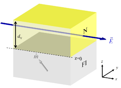
Here we derive an expression of the SMR for the bilayer in figure 2. We can generalize Ohm’s law for metals with a weak SHE, i.e., a small , as a relation between thermodynamic driving forces and currents that reflects Onsager’s reciprocity by the symmetry of the response matrix [69]:
| (57) |
where is the spin accumulation, i.e. the spin-dependent chemical potential relative to the charge chemical potential , is the electric conductivity, is the spin Hall angle, and “” denotes the vector cross product operating on the gradients of the spin-dependent chemical potentials. The SHE is represented by the “lower” non-diagonal elements that generate the spin currents in the presence of an applied electric field, in the following chosen to be in the -direction . The ISHE is governed by elements “above” the diagonal that connect the gradients of the spin accumulations to the charge current density. (57) is valid for cubic lattices such as Pt.
For films with thickness in the -direction as shown in figure 2, the general solution of the spin diffusion (37) reads
| (58) |
where the constant column vectors and are determined by the boundary conditions at the interfaces. We do not have to consider the charge accumulation since YIG is an insulator and the SOC does not generate any transverse charge current (via the AHE) as long as N remains non-magnetic.
According to (57), the spin current in N consists of conventional diffusion and spin Hall drift contributions. Assuming translational invariance in the - plane, we focus on the spin current density flowing in the -direction
| (59) |
where is the bare spin Hall current, i.e., the spin current generated directly by the SHE. The boundary conditions require that is continuous at the interfaces and . The spin current density at a vacuum interface () vanishes, while at the magnetic interface (), it is governed by the spin accumulation and spin-mixing conductance according to (41), , where the minus sign is due to that is flowing from N to F, i.e., in the -direction.
With these boundary conditions we can determine the coefficients and for the bilayer, which leads to the spin accumulation
| (60) |
where is the spin accumulation at the interface in the absence of spin-transfer, i.e., when .
-
0 0 -1 0 0 0 1 0 -0.28 0.28 0.72 0.28 -0.56 0 0.44 0
First we have a look at the spatial dependences of the spin current and spin accumulation. According to first principles calculations [83], is at least one order of magnitude smaller than for YIG, so appears to be a good first approximation. In this limit, the normalized components of spin current ( and ) and spin accumulation ( and ) at the top () and bottom () of N for different magnetizations are shown in table 1. When the magnetization of F is along , the spin current at the NF interface () vanishes just as for the vacuum interface. By rotating the magnetization from to , the spin current at the NF interface and the torque on the magnetization is activated, while the spin accumulation is dissipated correspondingly. The -components of both spin accumulation and spin current vanish when the magnetization is along and , and are largest at . This behavior agrees with the relations between spin current and spin-transfer torque at a NF interface discussed above.
The ISHE drives a charge current in the - plane by the diffusion spin current component flowing along the -direction. The total longitudinal (along ) and transverse or Hall (along ) charge currents become
| (63) | |||||
| (64) |
where is the charge current driven by the external electric field.
The charge current vector is usually expressed in terms of the longitudinal and transverse (Hall) resistivities. Averaging the electric currents over the film thickness and expanding the longitudinal resistivity or current in the (-)direction of the applied field to leading order in , we obtain
| (65) | |||||
| (66) |
where
| (67) | |||||
| (68) | |||||
| (69) |
and is the intrinsic electric resistivity of the bulk normal metal. The last approximations requires . We may not conclude from that SOC reduces the global resistivity, since the bulk itself is increased by spin-flip scattering in the bulk that is not explicitly treated here. For general magnetization and current directions (with film in the - plane) we can summarize the angle dependence as [6]
| (70) | |||||
| (71) |
(65-69) are the main results of the SMR model that can be compared with and fitted to experiments. We also note that the magnetization orientation dependence of the resistivity derived here holds for an isotropic N. In the presence of crystalline anisotropy, the angle dependence may involve higher harmonics [39].
4 Comparison with experiments
-
FI N (%) (nm) (m-2) method Ref. YIG Pt 11 1.5 1 A [31] 3 2.5 1 A [28] 8 1.5 0.3 A [30] 8 1.2 1.1 A [86] 11 1.5 1 ABC [92] 3 0.16 A+C [29] 5 2 0.26 C [110] 48 C [111] 3.43 C [112] 0.13 C [113] 1.3 2.5 B∗ [94] Ta -2 1.8 0.11 AC [29] -0.14 1.7 B∗ [94] Au 0.16 40 B [114] 0.3 9.5 B∗ [94] 0.12 C [115] 0.5 C [116] W -0.43 1.5 B∗ [94] CFO(001) Pt 0.65 A∗ [97] CFO(111) Pt 0.39 A∗ [97]
The SMR theory sketched above leads to simple analytic forms (65-69) that predict the magnetization dependence of the electric resistivity of the bilayers in terms of one sample parameter, i.e. the thickness , and four material parameters: the conductivity , spin Hall angle , spin diffusion length , and spin-mixing conductance , where is believed small and treated a posteriori by perturbation theory. The parameters may be fitted to SMR observations and other independent experiments such as ferromagnetic resonance (FMR) on the same bilayers.
While the SMR was discovered and filed as a patent as a remote detector of the magnetization direction of a ferromagnetic insulator a few years ago [35], the effect was first published in the supplemental material of [17]. Initially only the in-plane magnetization dependence was measured in PtYIG, which is phenomenologically identical to the conventional AMR. Weiler et al. therefore suspected that a proximity-induced ferromagnetic Pt layer could play a role [17], which implied that the spin Seebeck effect in PtYIG could be caused by an anomalous Nernst effect [27].
Subsequent experimental efforts addressed the dependence of the SMR when the magnetization is forced out of the interface plane, which revealed that the SMR is not consistent with a conventional AMR in a polycrystalline bulk material [28, 31]. While the SMR is proportional to according to (65) and (66), the conventional AMR depends on according to (5) and (6). These conclusions were confirmed by other experiments [30, 86, 29, 84, 85] also for bilayers with other metals such as Ta [29] and Pd [84, 85]. The current level required for SMR experiments can be kept low, but Joule heating artifacts can be excluded by using lock-in techniques or symmetry arguments [87, 88], as well.
Measurements on PtCuYIG and PtAuYIG provide more tests for the plausibility of a proximity effect. Cu and Au are diamagnetic and not susceptible to a ferromagnetic proximity effect. The persistence of an MR in the above trilayers can then be interpreted in terms of the spin Hall effect in Pt [28, 31] when the parallel conductance channels of the high-mobility Cu and Au spacer layers are taken into account, as shown in the supplementary material of [28].
The essential material-dependent parameters are assumed to be intensive, i.e. to not depend on the layer thicknesses, which is a debatable approximation (see section 5.2). They can then be determined by fitting (68) derived above to the experimental SMR for various . The spin Hall angle and spin diffusion length both reflect the SOC and might be correlated with each other [89], but we treat them here as independent phenomenological parameters [32]. The extracted parameters by different groups for the NFI [27, 28, 31], and those from earlier experiments e.g. FMR on metallic bilayers [36] are of the same order of magnitude. The transport parameters have been extracted from experiments of spin pumping detected by the ISHE in conjunction with SMR results on bilayers of PtYIG and TaYIG by Hahn et al. [29]: the thickness dependence of the ISHE voltage was used to fit the spin diffusion length using the expressions from [90]. The spin-mixing conductances can then be accurately fitted to the magnetoresistance because the ratio of the square of the spin pumping-ISHE voltage and the SMR does not depend on . They confirmed a different sign for Pt () and Ta () [91]. A systematic study including SSE, spin pumping (probed by the ISHE and FMR spectral broadening), and the SMR [92] led to a single set of parameters for these three effects, confirming the presumed identical physical origin. The real part of spin-mixing conductance appears to be in the interval for various samples [92]. The large value of the mixing conductance with YIG was predicted by first-principle calculations [83] and confirmed earlier by FMR experiments [116]. Parameters fitted from the SMR are listed in table 2 and compared with those obtained by other methods for NFI heterostructures.
Besides the planar Hall effect (the transverse corollary of a longitudinal MR), a Hall voltage that scales linear with the -component of the magnetization (normal to the film) has been observed, i.e. an anomaloul Hall-like effect that can be explained by the SMR mechanism when the imaginary part of the spin-mixing conductance in (69) is significant. Combining experiments on the magnetization direction and film thickness dependences, a value for can be extracted [31, 86] that agrees with first principle calculations [83]. Alternative explanations in terms of a conventional AHE in a magnetized monolayer of Pt or surface roughness, however, cannot be excluded as discussed in section 5.
The SMR has been observed in bilayers made from other metals than Pt such as Ta, Pd, W, Nb, and Rh [29, 93, 84, 85, 94, 95, 96], and other magnetic insulators besides YIG [31, 97, 99]. In PtCFO (CFO: CoFe2O4) bilayers, the spin-mixing conductance was found to strongly depend on the crystallographic interface orientation, possibly due to different densities of magnetic moments [97], which should be confirmed by spin pumping and SSE experiments and first principle calculations. The dependence of the SMR on the magnetic ordering at the interface provides a convenient tool to probe the interface magnetization of the FI, which can be very different from the bulk magnetization [98]. The SMR with Pt on the antiferromagnet SrMnO3 was found to be finite only when a net magnetization was induced by an applied magnetic field [99]. Since a current-induced spin-transfer torque has been predicted for antiferromagnets [100, 101], we expect an SMR also for unpolarized, single-domain antiferromagnets.
The SMR has been observed for PtFe3O4 bilayers at low [31] and room temperatures [102]. Fe3O4 is not an insulator, but a bad metal with resistivity about five orders of magnitude larger than that of PtFe3O4 and a possible AMR in the ferrite is likely to be shunted [102]. The SMR is also observed in metallic layered systems, even though its interpretation is more difficult due to currents in the ferromagnet and possibly more serious proximity effects. MR measurements in PtCoPt and PtPyPt trilayers [103, 104] found a magnetization dependence that is a combination of the AMR and what we now call SMR phenomenology, revealing that the SMR could be present also in all-metallic samples. In TaCo, PtCo and WPt, a difference in the resistance by, respectively, two (TaCo) and three (PtCo and WPt) orders of magnitude smaller than AMRSMR was found in NFM bilayers for magnetizations parallel and antiparallel to [105, 106]. Indeed, in ferromagnetic metals (in contrast to insulators) the reflection of the spin Hall current at the interface is incomplete and differs when parallel and antiparallel to the magnetization [105]. To capture this contribution, one may have to extend the SMR model by including the diffusive transport in F and fitting the boundary condition with (10) rather than with (41). It was reported that in Ga0.91Mn0.09AsGa0.97Mn0.03As (FMNM), this difference in MR can be in the same order of the SMRAMR [107]. An SMR in metallic bilayers WCoFeB has been reported to be an order of magnitude larger than that in NFI, which was interpreted in terms of a spin Hall angle for -tungsten [108, 109]. A complete model for the spin-orbit torques in bilayers should explain the observed correlation between the SMR amplitude and current-induced magnetization switching in these bilayers [109].
5 Issues
Here we address controversial and unsolved issues concerning the interpretation of experiments in terms of the SMR mechanism.
5.1 Magnetic proximity effects
As mentioned above, the observation of a magnetoresistance in Pt on a magnetic insulator could in principle be caused by the equilibrium magnetic proximity effect (MPE). Pt and Pd have Stoner-enhanced magnetic susceptibilities and are therefore “almost” ferromagnetic [117]. For instance, magnetic impurities in these metals have a strongly enhanced magnetic moment. The MPE is well established in bilayers made of a normal metal and a ferromagnetic metal. X-ray magnetic circular dichroism (XMCD) [118] detected a large polarization at the interface of Pt on a magnetic metal [119, 120, 121, 122, 123] as compared to less-susceptible metals. For example, the MPE in AuCo is about one order of magnitude smaller than that in PtCo [124]. XMCD studies on PtYIG led to conflicting results [125, 126]. Theoretically, spin-polarized density functional calculations for PtYIG and AuYIG found the Pt spin polarization in PtYIG to be stronger than that of Au in AuYIG [114]. However, since YIG is a ferrimagnet with a much smaller saturation magnetization, the MPE in PtYIG may be expected be smaller than that for strongly ferromagnetic metals. Guo et al. [127] predicted a significant magnetotransport effect in slightly magnetized Pt. However, these calculations are for bulk materials and cannot be used to model a monolayer-scale proximity effect on a magnetic insulator. We are not aware of a realistic theoretical model for magnetotransport dominated by the MPE.
Kikkawa et al. [128] addressed the possible contribution of an MPE-induced anomalous Nernst effect (ANE) generated by an in-plane temperature gradient over a PtYIG bilayer with an out-of-plane magnetization. The observed Hall voltage was less than of that for an in-plane magnetization and out-of-plane temperature gradient, i.e. the sum of the ANE and the SSE, leading to the conclusion that an MPE-induced ANE may be disregarded.
The reported temperature dependence of the SMR is not unequivocal. Some groups only find a decrease of the SMR amplitude at low temperatures (see section 6.2), others report an increasingly significant AMR contribution in PdYIG [85], TaYIG [93], IrMnYIG [129], PtYIG [129], PtCo2FeAl [130], and PtLaCoO3 [131] that might indicate a low temperature MPE. Puzzling is the sign change of the AHE-like SMR at temperatures between a few Kelvin and room temperature [94, 132, 129, 131], suggesting either a temperature-dependent or a new low-temperature transport phenomenon, possibly caused by the MPE or interface disorder (discussed in section 5.2). An AHE-like signal at low temperatures and at magnetic fields higher than the saturation field of YIG [84, 133] is interpreted as evidence for a hard magnetization texture of unknown character at the interface. Further studies are required to shed light on the physical mechanisms that may affect the MR at low temperatures. At room temperature, the simple SMR model appears to be as yet unchallenged.
5.2 Interface roughness and AHE-like SMR
Surface roughness scattering disregarded here affects many in-plane transport properties of ultrathin metallic films. These effects can in principle be modeled by semiclassical Boltzmann or diffusion theories [134, 135]. When the metallic films become thinner, their resistivity increases by either reduced crystal quality or the increased importance of surface roughness. Parameters such as the spin-flip diffusion length and spin Hall angle may become thickness dependent as well. The AMR of thin films of metallic ferromagnets is known to be affected by surface roughness [41, 42]. The spin-dependent scattering at rough interfaces is invoked to explain the current in-plane giant magnetoresistance [53]. The SHE and the SMR in NFI should also be affected by roughness at the interface causing, for example, a spin-dependent mean-free path in the normal metal even without an equilibrium MPE. Interface roughness has minor effects on the spin-mixing conductance (when the SOC is small) [64]. Moreover, for out-of-plane magnetizations, spin-dependent roughness can drive a transverse charge current by the ISHE, competing with the contribution from the imaginary part of the spin-mixing conductance in (69). While (69) is a second-order contribution of the SOC, the contribution due to the spin-dependent roughness scales linearly to [136, 137]. The two mechanisms can therefore be distinguished by measurements on materials with opposite signs of spin Hall angle such as Pt and Ta [137].
Experimentally, the SMR in PtFMMgO with (sub) monolayer ( or nm) Co2FeAl was explained in terms of an interference of spin-dependent scattering at magnetic clusters and the SHE [130]. A quantitative analysis of the effects of roughness might be possible if induced by controlled ion bombardment [138, 139].
5.3 Interface spin-orbit couplings
The SMR model attributes the spin polarization to the SHE, which requires the SOC in the bulk layer, but disregards the SOC at the FN interface. However, interface SOC can modulate transport parameters that can be separated from bulk effects experimentally only by tedious thickness-dependent studies. A material-dependent theory of spin transport through FN interfaces is not available. However, an effective spin-mixing conductance can parameterize computed results for the spin pumping contribution to the Gilbert damping and interface spin flips [140] in NPyN sandwiches [79]. Such an effective spin-mixing conductance appears to be not very sensitive to the SOC for intermetallic interfaces such as PyPt [79]. A large spin-mixing conductance has been reported for PyCuYIG [141]. Experiments with non-local spin valves on a YIG substrated were interpreted in terms of a finite CuYIG spin-mixing conductance; its relatively small value might be caused by interface contamination [142]. By a similar technique, i.e. using a non-local PyAl spin valves on a YIG substrate, Dejene et al. [143] distill a large mixing conductance, but the modulation as a function of YIG magnetization direction is smaller than expected, which can be explained by thermal fluctuations [144, 73, 162] (see section 6.2).
The Edelstein effect refers to a current-induced spin accumulation with polarization normal to the current direction in the plane of the two-dimensional electron gas in which inversion symmetry is broken by a normal electric field that can be described by the Rashba Hamiltonian [145]. The Rashba Hamiltonian has been invoked also for thin metallic films, in which non-equivalent interfaces are the source of the inversion symmetry-breaking [67, 68]. An MR was predicted for NFI bilayers in the presence of a Rashba interaction at the interface (and without SHE in the bulk) that depends on the magnetization direction just like the SMR [146]. Other theoretical studies of the MR in ferromagnetic metallic thin films on a conventional insulating substrate with Rashba SOC based on the Boltzmann equation [147, 148] also predict a contribution to the magnetoresistance which has the same magnetization dependence as the SMR () but a different thickness dependence [148]. Thus in principle, thickness-dependent studies could help distinguish these different mechanisms.
Recent positron annihilation experiments observed current-induced spin polarizations in normal metal films without proximity ferromagnets [149, 150]. The measured spin polarization is about one order of magnitude larger than that estimated by the diffusive SHE model defined as in section 3.3. The authors attribute the observations to the Edelstein effect [66], i.e. a spin accumulation with an in-plane polarization normal to the applied current direction in a surface state, which may be interpreted as a two-dimensional limit of the SHE. Jellium model calculations suggest a universal current-induced spin polarization at metallic surfaces of [151], where is a material dependent constant that appears to be large for Pt and Ta, but small for Au and Cu [150].
6 Developments
We discuss in the following ongoing developments related to the SMR.
6.1 Dynamics
The SMR model took the magnetization in the FI to be static, which is not generally the case since spin currents absorbed by the FI generate spin-transfer torques which can amplify or attenuate [152] and even generate spin waves [70]. The threshold current for spin wave excitations in NFI is higher than found in the experiments even when easy-axis magnetic surface anisotropy is taken into account [153, 154, 155]. Recent experiments show that current-induced auto-oscillation in YIG can be achieved by current densities as predicteed, but only when reducing the lateral dimensions of the FI [71].
An ac SMR, or the spin Hall magnetoimpedance, was observed experimentally [156] to persists up to at least GHz, allowing fast readouts of the magnetization in NFI bilayers. The SMR also allows observation of spin torque induced FMR [157], i.e. the observation of a dc voltage by down conversion of an applied ac current by the oscillating resistance under resonance. Schreier et al. [158] and Sklenar et al. [159] separate the effects of the spin-transfer torque from that of Oersted fields generated by the applied ac current and spin pumping from the SMR rectification by comparing samples with different YIG and Pt thickness [158, 159]. This technique appears to be more sensitive than applying microwaves via a coplanar wave guide [160].
6.2 Temperature dependence
As a zero temperature theory, the SMR model described here assumes perfect reflection of a spin current with spin polarization collinear to the magnetization. At finite temperatures, the magnetization fluctuates and thereby allows for a finite spin current even for collinear configurations [144, 73, 161, 162]. The SMR model thereby overestimates the magnetoresistance. A larger than expected loss of spin accumulation in collinear configurations has been inferred from experiments for YIGAl [143], which could imply that the spin-mixing conductances fitted to room temperature SMR experiments are underestimated.
In bilayers of Pt, Ta, and Pd with YIG [164, 163, 93, 84, 85]. SMR decrease with temperature when going from K to K. This contradicts the (above) notion of a spin current in the collinear configuration that is induced by thermal fluctuations, which should lead to a larger SMR at lower temperatures. The effect might be caused by a temperature dependence of the spin Hall angle [164]. A non-monotonic temperature dependence of the SMR in PtYIG and PdYIG with a maximum at K was explained in terms of a spin diffusion length that is inversely proportional to the temperature, as expected from the Elliot-Yafet impurity scattering model [163, 85]. In the regime from ambient to the Curie temperature of YIG, the SMR decreases monotonically as expected [165]. The observation that the SMR decreases with temperature at a higher power than the magnetization could be caused by a temperature-dependent spin-mixing conductance [165].
Spin currents generated in a lateral FNF spin valve can be absorbed by another contact (N2) placed between the magnetic electrodes on the path of the diffusive spin current in N1. This technique gives access to the spin diffusion length and spin Hall angle (via the ISHE) of N2 [50, 166], and was used to measure their temperature dependence for Pt and Au [167, 168]. In Pt, both spin Hall angle and electric resistivity are found to increase linearly with temperature, implying an intrinsic mechanism for the spin Hall conductivity [6], while the SHE in Au appears to be dominated by extrinsic effects [167]. Such an analysis could be helpful to clarify the microscopic mechanism responsible for the temperature dependence of the SMR.
The spin Seebeck effect in gadolinium (Gd) iron garnet (Gd3Fe5O12) [169] changes sign twice when the temperature is lowered from K to K, and is explained in terms of different contributions from the magnetic sublattices. Experimental results for the temperature dependence of the SMR of rare earth iron garnets might help establishing the importance of interface vs. bulk effects to explain this intriguing phenomenon.
6.3 Spin valves and superlattices
The magnetizations in FINFI spin valves can be coupled, in the ground states by dipolar and non-local exchange interactions. A dynamic exchange interaction is generated by spin current emission and absorption when magnetizations are moving [115]. The magnetic state can be detected by the SMR, which is enhanced when the magnetizations are collinear and reduced when perpendicular to each other [32]. The SHE interferes when the charge current through the spacer becomes appreciable. Applied currents were found to modulate the damping of FINFI spin valve and superlattice dynamics. The critical currents to excite magnetization dynamics (macrospin and spin waves) depend on the relative orientations of magnetizations [170]. The dynamic coupling between spin waves due to spin pumping and spin-transfer torques is in general mode-dependent [171].
6.4 Bilayers of insulating and metallic magnets
Recent studies address bilayers made of a metallic ferromagnet such as permalloy and a ferromagnetic insulator such as YIG [104, 138, 172, 173, 141, 174, 175]. The MR in these systems [104, 138, 172] can be fully explained neither by the conventional AMR nor by the SMR theory that only holds for paramagnetic conductors. The MPE can induce a magnetic moment on a highly susceptible paramagnet, but should have minor effects on a strong ferromagnet, although Lu et al. [104] argue otherwise. The Hall voltages induced by thermal [138] and FMR [173] spin pumping have been interpreted in terms of the spin Hall angle of the ferromagnet, where Tsukahara et al. extracted a spin Hall angle of for Py. It was pointed out that dc Hall voltages can be generated as well by spin rectification caused by the dynamics and the AMR in Py [175]. Spin pumping as detected by Hall voltages in WPyYIG trilayers indicate opposite signs of the spin Hall angles in Py and W [141]. However, the mechanism of spin pumping into a metallic ferromagnet is not yet fully understood [174], so estimates of the spin Hall angle in magnetic metals should be taken with a grain of salt. By decoupling Py and YIG with a copper spacer layer [141], the problem becomes amenable to the conventional theory, however, a for Py was deduced. First principles calculations predict extrinsic spin Hall angles in diluted ferromagnetic alloys of [176].
7 Conclusions/outlook
The discovery of a magnetoresistance in nominally non-magnetic metals next to magnetic insulators has stimulated many subsequent studies. Experiments from different groups and sample growth techniques yield consistent results that are well reproduced by a few-parameter, simple and intuitive model called “spin Hall magnetoresistance (SMR)” that explains the observations by the concerted action of the direct and inverse spin Hall effects. While providing a convenient parametrization scheme, the detailed physics and material dependence is still a matter of discussion. By using an exchange-only theory of spin-transfer torque, the effect of interfacial spin-orbit coupling (SOC) is disregarded. This does not necessarily reduce the quality of the fits, but the parameters must then be considered to represent an effective average of interface and bulk contributions with the same symmetry. Fitting parameters that depend strongly on the thickness of the normal metal film have not been reported to date. First-principles calculations including the SOC and disorder such as those by Liu et al. [79] should be able to shed more light on this issue. Measurements at low temperatures and high magnetic fields have been interpreted in terms of a magnetic proximity effect [84, 85, 93, 94, 129, 130, 131, 132, 133], although even a qualitative theory in support of this conjecture is lacking. XMCD experiments that in principle provide a definite answer lead to contradicting results [125, 126]. Also here first-principles calculation may importantly help to not only estimate the magnitude and penetration of the induced moments, but also its effects on transport and taking into account the magnetic fluctuations induced by finite temperatures [177].
The SMR has been employed to study spin-correlations in antiferromagnets [99] and multiferroic materials [178]. In these studies a magnetic field has to be applied in order to observe a finite SMR, which implies that an interface magnetic susceptibility is sampled, rather than a ground state spin texture. While the SMR is a sensitive detector for subtle spin correlations [178], more work is needed to better understand the implications. The spin Seebeck effect in paramagnets under strong magnetic fields [179] should be accompanied by an SMR. The SMR has been observed in the current-direction dependence of the Johnson-Nyquist noise of YIGPt bilayers, which can be understood in terms of the fluctuation dissipation theorem [180]. Another direction worth exploring are thermal analogies of the SMR [181]: we may, e.g., expect a dependence of the in-plane thermopower on the magnetization direction in NFI bilayers as a fingerprint of the spin Nernst effect. Very recently, a non-local SMR (or magnon-drag effect [182]) was observed in PtYIG Pt lateral heterostructures [183, 184], in which a current in one contact generates a voltage in the other contact that is maximal when both are normal to the magnetization direction.
References
References
- [1] Bader S D and Parkin S S P 2010 Ann. Rev. Cond. Matt. Phys. 1 71
- [2] Sinova J and Žutić I 2012 Nature Mater. 11 368
- [3] Suzuki Y 2012 Spin Currents ed S Maekawa et al (U K: Oxford University Press) p 343
- [4] Jungwirth T, Wunderlich J and Olejník K 2012 Nature Mater. 11 382
- [5] Hoffmann A 2013 IEEE Trans. Magn. 49 5172
- [6] Sinova J, Valenzuela S O, Wunderlich J, Back C H and Jungwirth T 2015 Rev. Mod. Phys. 87 1213
- [7] Ando K, Takahashi S, Harii K, Sasage K, Ieda J, Maekawa S and Saitoh E 2008 Phys. Rev. Lett. 101 036601
- [8] Miron I M, Garello K, Gaudin G, Zermatten P-J, Costache M V, Auffret S, Bandiera S, Rodmacq B, Schuhl A and Gambardella P 2011 Nature 476 189
- [9] Liu L, Pai C F, Li Y, Tseng H W, Ralph D C and Buhrman R A 2012 Science 336 555
- [10] Saitoh E, Ueda M, Miyajima H and Tatara G 2006 Appl. Phys. Lett. 88 182509
- [11] Mosendz O, Pearson J E, Fradin F Y, Bauer G E W, Bader S D and Hoffmann A 2010 Phys. Rev. Lett. 104 046601
- [12] Mosendz O, Vlaminck V, Pearson J E, Fradin F Y, Bauer G E W, Bader S D and Hoffmann A 2010 Phys. Rev. B 82 214403
- [13] Czeschka F D et al 2011 Phys. Lett. Rev. 107 046601
- [14] Uchida K, Takahashi S, Harii K, Ieda J, Koshibae W, Ando K, Maekawa S and Saitoh E 2008 Nature 455 778
- [15] Jaworski C M, Yang J, Mack S, Awschalom D D, Heremans J P and Myers R C 2010 Nature Mater. 9 898
- [16] Uchida K et al 2010 Nature Mater. 9 894
- [17] Weiler M et al 2012 Phys. Rev. Lett. 108 106602
- [18] Uchida K, Ishida M, Kikkawa T, Kirihara A, Murakami T and Saitoh E 2014 J. Phys.: Condens. Matter 26 343202
- [19] Wu M and Hoffmann A (eds) 2013 Recent Advances in Magnetic Insulators – From Spintronics to Microwave Applications (Solid State Physics vol 64) (San Diego, CA: Elsevier Inc.)
- [20] Ashcroft N W and Mermin N D 1976 Solid State Physics (Philadelphia, PA: Saunders)
- [21] Thomson W 1857 Proc. R. Soc. London 8 546
- [22] McGuire T R and Potter R I 1975 IEEE Trans. Magn. MAG-11 1018
- [23] Thompson D A, Romankiw L T and Mayadas A F 1975 IEEE Trans. Magn. MAG-11 1039
- [24] Fert A 2008 Rev. Mod. Phys. 80 1517
- [25] Yuasa S 2008 J. Phys. Soc. Jpn. 77 031001
- [26] Moodera J S, Miao G-X and Santos T S 2010 Phys. Today 63(4) 46
- [27] Huang S Y, Fan X, Qu D, Chen Y P, Wang W G, Wu J, Chen T Y, Xiao J Q and Chien C L 2012 Phys. Rev. Lett. 109 107204
- [28] Nakayama H et al 2013 Phys. Rev. Lett. 110 206601
- [29] Hahn C, de Loubens G, Klein O, Viret M, Naletov V V and Ben Youssef J 2013 Phys. Rev. B 87 174417
- [30] Vlietstra N, Shan J, Castel B, van Wees B J and Ben Youssef J 2013 Phys. Rev. B 87 184421
- [31] Althammer M et al 2013 Phys. Rev. B 87 224401
- [32] Chen Y-T, Takahashi S, Nakayama H, Althammer M, Goennenwein S T B, Saitoh E and Bauer G E W 2013 Phys. Rev. B 87 144411
- [33] Dyakonov M I 2007 Phys. Rev. Lett. 99 126601
- [34] Vélez S, Golovach V N, Bedoya-Pinto A, Isasa M, Sagasta E, Abadia M, Rogero C, Hueso L E, Bergeret F S and Casanova F 2016 Phys. Rev. Lett. 116 016603
- [35] Saitoh E, Nakayama H and Harii K 2010 Magnetic sensor and magnetic-storage device, Patent No. WO 2010110297 A1
- [36] Liu L, Buhrman R A and Ralph D C 2011 Review and Analysis of Measurements of the Spin Hall Effect in Platinum arXiv:1111.3702
- [37] Mott N 1936 Proc. R. Soc. 153 699
- [38] Hall E 1881 Phil. Mag. 12 157
- [39] Limmer W, Glunk M, Daeubler J, Hummel T, Schoch W, Sauer R, Bihler C, Huebl H, Brandt M S and Goennenwein S T B 2006 Phys. Rev. B 74 205205
- [40] Kokado S, Tsunoda M, Harigaya K and Sakuma A 2012 J. Phys. Soc. Jpn. 81 024705
- [41] Rijks Th G S M, Coehoorn R, de Jong M J M and de Jonge W J M 1995 Phys. Rev. B 51 283
- [42] Rijks Th G S M, Lenczowski S K J, Coehoorn R and de Jonge W J M 1997 Phys. Rev. B 56 362
- [43] Rowan-Robinson R M, Hindmarch A T and Atkinson D 2014 Phys. Rev. B 90 104401
- [44] Hall E H 1879 Am. J. Math. 2 287
- [45] For a review see: Nagaosa N, Sinova J, Onoda S, MacDonald A H and Ong N P 2010 Rev. Mod. Phys. 82 1539
- [46] Onoda S, Sugimoto N, Nagaosa N 2008 Phys. Rev. B 77 165103 and references therein
- [47] Tian Y, Ye L and Jin X 2009 Phys. Rev. Lett. 103 087206
- [48] Kato Y K, Myers R C, Gossard A C and Awschalom D D 2004 Science 306 1910
- [49] Valenzuela S O and Tinkham M 2006 Nature 442 176
- [50] Kimura T, Otani Y, Sato T, Takahashi S and Maekawa S 2007 Phys. Rev. Lett. 98 156601
- [51] Baibich M N, Broto J M, Fert A, Nguyen Van Dau F, Petroff F, Etienne P, Creuzet G, Friederich A and ChazelasJ 1988 Phys. Rev. Lett. 61 2472
- [52] Binasch G, Grünberg P, Saurenbach F and Zinn W 1989 Phys. Rev. B 39 4828
- [53] Camley R E and Barnaś J 1989 Phys. Rev. Lett. 63 664
- [54] Pratt Jr W P, Lee S-F, Slaughter J M, Loloee R, Schroeder P A and Bass J 1991 Phys. Rev. Lett. 66 3060
- [55] Gijs M A M, Lenczowski S K J and Giesbers J B 1993 Phys. Rev. Lett. 70 3343
- [56] Gijs M A M and Bauer G E W 1997 Adv. Phys. 46 285
- [57] Valet T and Fert A 1993 Phys. Rev. B 48 7099
- [58] Slonczewski J C 1996 J. Magn. Magn. Mater. 159 L1
- [59] Berger L 1996 Phys. Rev. B 54 9353
- [60] Tsoi M, Jansen A G M, Bass J, Chiang W-C, Seck M, Tsoi V and Wyder P 1998 Phys. Rev. Lett. 80 4281
- [61] Sun J Z 1999 J. Magn. Magn. Mater. 202 157
- [62] Myers E B, Ralph D C, Katine J A, Louie R N and Buhrman R A 1999 Science 285 867
- [63] Katine J A, Albert F J, Buhrman R A, Myers E B and Ralph D C 2000 Phys. Rev. Lett. 84 3149
- [64] Brataas A, Bauer G E W and Kelly P J 2006 Phys. Rep. 427 157
- [65] Gambardella P and Miron I M 2010 Phil. Trans. R. Soc. A 369 3175
- [66] Edelstein V M 1990 Solid State Commun. 73 233
- [67] Manchon A and Zhang S 2008 Phys. Rev. B 78 212405
- [68] Manchon A and Zhang S 2009 Phys. Rev. B 79 094422
- [69] Takahashi S, Imamura H and Maekawa S 2006 Concepts in Spin Electronics ed S Maekawa et al (U K: Oxford University Press) p 343
- [70] Kajiwara Y et al 2010 Nature 464 262
- [71] Collet M, de Milly X, d’Allivy Kelly O, Naletov V V, Bernard R, Bortolotti P, Demidov V E, Demokritov S O, Prieto J L, Muñoz M, Cros V, Anane A, de Loubens G, and Klein O 2015 Generation of coherent spin-wave modes in Yttrium Iron Garnet microdiscs by spin-orbit torque arXiv:1504.01512
- [72] Sandweg C W, Kajiwara Y, Chumak A V, Serga A A, Vasyuchka V I, Jungfleisch M B, Saitoh E and Hillebrands B 2011 Phys. Rev. Lett. 106 216601
- [73] Flipse J, Dejene F K, Wagenaar D, Bauer G E W, Ben Youssef J and van Wees B J 2014 Phys. Rev. Lett. 113 027601
- [74] Xiao J, Bauer G E W, Uchida K, Saitoh E and Maekawa S 2010 Phys. Rev. B 81 214418
- [75] Adachi H, Uchida K, Saitoh E and Maekawa S 2013 Rep. Prog. Phys. 76 036501
- [76] van Son P C, van Kempen H and Wyder P 1987 Phys. Rev. Lett. 58 2271
- [77] Hershfield S and Zhao H L 1997 Phys. Rev. B 56 3296
- [78] Fert A and Campbell I A 1971 J. Phys. (Paris), Colloq. 32 C1-46
- [79] Liu Y, Yuan Z, Wesselink R J H, Starikov A A and Kelly P J 2014 Phys. Rev. Lett. 113 207202
- [80] Wang L, Wesselink R J H, Liu Y, Yuan Z, Xia K and Kelly P J 2015 First-principles calculation of the spin-Hall and inverse spin-Hall effects: interface versus bulk contributions arXiv:1512.07418
- [81] Schep K M, van Hoof J B A N, Kelly P J, Bauer G E W and Inglesfield J E 1997 Phys. Rev. B 56 10805
- [82] Bauer G E W, Tserkovnyak Y, Huertas-Hernando D and Brataas A 2003, Phys. Rev. B 67, 094421 (2003)
- [83] Jia X, Liu K, Xia K and Bauer G E W 2011 Eurphys. Lett. 96 17005
- [84] Lin T, Tang C and Shi J 2013 Apply. Phys. Lett. 103 132407
- [85] Lin T, Tang C, Alyahayaei H M and Shi J 2014 Phys. Rev. Lett. 113 037203
- [86] Vlietstra N, Shan J, Castel V, Ben Youssef J, Bauer G E W and van Wees B J 2013 Appl. Phys. Lett. 103 032401
- [87] Vlietstra N, Shan J, van Wees B J, Isasa M, Casanova F and Ben Youssef J 2014 Phys. Rev. B 90 174436
- [88] Schreier M, Roschewsky N, Dobler E, Meyer S, Huebl H, Gross R and Goennenwein S T B 2013 Apply. Phys. Lett. 103 242404
- [89] Schreier M, Weiler M, Huebl H and Goennenwein S T B 2014 unpublished
- [90] Castel V, Vlietstra N, Ben Youssef J and van Wees B J 2012 Appl. Phys. Lett. 101 132414
- [91] Schreier M et al 2015 J. Phys. D: Appl. Phys. 48 025001
- [92] Weiler M et al 2013 Phys. Rev. Lett. 111 176601
- [93] Yang Y, Wu B, Yao K, Shannigrahi S, Zong B and Wu Y 2014 J. Appl. Phys. 115 17C509
- [94] Qu D, Huang S Y, Miao B F, Huang S X and Chien C L 2014 Phys. Rev. B 89 140407(R)
- [95] Han J H, Wang Y Y, Yang Q H, Wang G Y, Pan F and Song C 2015 Phys. Status Solidi RRL. 9 371
- [96] Shang T et al 2015 Sci. Rep. 5 17734
- [97] Isasa M, Bedoya-Pinto A, Vélez S, Golmar F, Sánchez F, Hueso L E, Fontcuberta J and Casanova F 2014 Appl. Phys. Lett. 105 142402
- [98] Isasa M, Sagasta E, Bedoya-Pinto A, Velez S, Dix N, Sanchez F, Hueso L E, Fontcuberta J and Casanova F 2015 Spin Hall magnetoresistance as a probe for surface magnetization in Pt/CoFe2O4 bilayers arXiv:1510.01449
- [99] Han J H, Song C, Li F, Wang Y Y, Wang G Y, Yang Q H and Pan F 2014 Phys. Rev. B 90 144431
- [100] Takei S, Halperin B I, Yacoby A and Tserkovnyak Y 2014 Phys. Rev. B 90 094408
- [101] Cheng R, Xiao J, Niu Q and Brataas A 2014 Phys. Rev. Lett. 113 057601
- [102] Ding Z, Chen B L, Liang J H, Zhu J, Li J X and Wu Y Z 2014 Phys. Rev. B 90 134424
- [103] Kobs A, Heße S, Kreuzpaintner W, Winkler G, Lott D, Weinberger P, Schreyer A and Oepen H P 2011 Phys. Rev. Lett. 106 217207
- [104] Lu Y M, Cai J W, Huang S Y, Qu D, Miao B F and Chien C L 2013 Phys. Rev. B 87 220409(R)
- [105] Avci C O, Garello K, Ghosh A, Gabureac M, Alvarado S F and Gambardella P 2015 Nature Phys. 11 570
- [106] Avci C O, Garello K, Mendil J, Ghosh A, Blasakis N, Gabureac M, Trassin M, Fiebig M and Gambardella P 2015 Appl. Phys. Lett. 107 192405
- [107] Olejník K, Noák V, Wunderlich J and Jungwirth T 2015 Phys. Rev. B 91 180402(R)
- [108] Kim J, Sheng P, Takahashi S, Mitani S and Hayashi M 2015 Giant spin Hall magnetoresistance in metallic bilayers arXiv:1503.08903
- [109] Cho S, Baek S-H C, Lee K-D, Jo Y and Park B-G 2015 Sci. Rep. 5 14668
- [110] Hahn C, de Loubens G, Viret M, Klein O, Naletov V V and Ben Youssef J 2014 Phys. Rev. Lett. 111 217204
- [111] Rezende S M, Rodríguez-Suárez R L, Soares M M, Vilela-Leão L H, Ley Domínguez D and Azevedo A 2013 Appl. Phys. Lett. 102 012402
- [112] Jungfleisch M B, Lauer V, Neb R, Chumak A V and Hillebrands B 2013 Appl. Phys. Lett. 103 022411
- [113] Qiu Z, Ando K, Uchida K, Kajiwara Y, Takahashi R, Nakayama H, An T, Fujikawa Y and Saitoh E 2013 Appl. Phys. Lett. 103 092404
- [114] Qu D, Huang S Y, Hu J, Wu R and Chien C L 2013 Phys. Rev. Lett. 110 067206
- [115] Heinrich B, Burrowes C, Montoya E, Kardasz B, Girt E, Song Y Y, Sun Y and Wu M 2011 Phys. Rev. Lett. 107 066604
- [116] Burrowes C, Heinrich B, Kardasz B, Montoya E A, Girt E, Sun Y, Song Y Y and Wu M 2012 Appl. Phys. Lett. 100 092403
- [117] Buschow K H J and de Boer F R 2003 Physics of Magnetism and Magnetic Materials (Springer US)
- [118] Wende H 2004 Rep. Prog. Phys. 67 2105
- [119] Rüegg S, Schütz G, Fischer P, Wienke R, Zeper W B and Ebert H 1991 J. Appl. Phys. 69 5655
- [120] Antel W J, Jr., Schwickert M M, Lin T, O’Brian W L and Harp G R 1999 Phys. Rev. B 60 12993
- [121] Wilhelm F et al 2000 Phys. Rev. Lett. 85 413
- [122] Wilhelm F, Poulopoulos P, Wende H, Scherz A, Baberschke K, Angelakeris M, Flevaris N K and Rogalev A 2001 Phys. Rev. Lett. 87 207202
- [123] Meier F, Lounis S, Wiebe J, Zhou L, Heers S, Mavropoulos P, Dederichs P H, Blügel S and Wiesendanger R 2011 Phys. Rev. B 83 075407
- [124] Wilhelm F, Angelakeris M, Jaouen N, Poulopoulos P, Papaioannou E Th, Mueller Ch, Fumagalli P, Rogalev A and Flevaris N K 2004 Phys. Rev. B 69 220404(R)
- [125] Geprägs S, Meyer S, Altmannshofer S, Opel M, Wilhelm F, Rogalev A, Gross R and Goennenwein S T B 2012 Appl. Phys. Lett. 101 262407
- [126] Lu Y M, Choi Y, Ortega C M, Cheng X M, Cai J W, Huang S Y, Sun L and Chien C L 2013 Phys. Rev. Lett. 110 147207
- [127] Guo G Y, Niu Q and Nagaosa N 2014 Phys. Rev. B 89 214406
- [128] Kikkawa T, Uchida K, Shiomi Y, Qiu Z, Hou D, Tian D, Nakayama H, Jin X-F and Saitoh E 2013 Phys. Rev. Lett. 110 067207
- [129] Zhou X, Ma L, Shi Z, Fan W-J, Zheng J-G, Evans R F L and Zhou S M 2015 Phys. Rev. B 92 060402(R)
- [130] Zhang Y-Q, Fu H R, Sun N-Y, Che W-R, Ding D, Qin J, You C-Y, Zhu Z-G and Shan R 2015 Redefinition of spin Hall magnetoresistance arXiv:1502.04288
- [131] Shang T et al 2015 Phys. Rev. B 92 165114
- [132] Meyer S, Schlitz R, Geprägs S, Opel M, Huebl H, Gross R and Goennenwein S T B 2015 Appl. Phys. Lett. 106 132402
- [133] Miao B F, Huang S Y, Qu D and Chien C L 2014 Phys. Rev. Lett. 112 236601
- [134] Fuchs K 1938 Proc. Cambridge Philos. Soc. 34 100
- [135] Sondheimer E H 1952 Adv. Phys. 1 1
- [136] Chen Y-T 2014 Ph.D. thesis (Delft-Leiden, Casimir PhD Series)
- [137] Zhang S S-L and Vignale G 2015 Nonlocal Anomalous Hall Effect arXiv:1512.04146
- [138] Miao B F, Huang S Y, Qu D and Chien C L 2013 Phys. Rev. Lett. 111 066602
- [139] Shan J, Vlietstra N and van Wees B J 2013 private communication
- [140] Bass J and Pratt Jr W P 2007 J. Phys.: Condens. Matter 19 183201
- [141] Wang H, Du C, Hammel P C and Yang F 2014 Appl. Phys. Lett. 104 202405
- [142] Villamor E, Isasa M, Vélez S, Bedoya-Pinto A, Vavassori P, Hueso L E, Bergeret F S and Casanova F 2015 Phys. Rev. B 91 020403(R)
- [143] Dejene F K, Vlietstra N, Luc D, Waintal X, Ben Youssef J and van Wees B J 2015 Phys. Rev. B 91 100404(R)
- [144] Cahaya A B, Tretiakov O A and Bauer G E W 2014 Appl. Phys. Lett. 104 042402
- [145] Bychkov Y A and Rashba E I 1984 JETP Lett. 39 78
- [146] Grigoryan V L, Guo W, Bauer G E W and Xiao J 2014 Phys. Rev. B 90 161412(R)
- [147] Zhang S S-L and Zhang S 2014 J. Appl. Phys. 115 17C703
- [148] Zhang S S-L, Vignale G and Zhang S 2015 Phys. Rev. B 92 024412
- [149] Kawasuso A, Fukaya Y, Maekawa M, Zhang H, Seki T, Yoshino T, Saitoh E and Takanashi K 2013 J. Magn. Magn. Mater. 342 139
- [150] Zhang H J, Yamamoto S, Fukaya Y, Maekawa M, Li H, Kawasuso A, Seki T, Saitoh E and Takanashi K 2014 Sci. Rep. 4 4844
- [151] Tokatly I V, Krasovskii E E and Vignale G 2015 Phys. Rev. B 91 035403
- [152] Wang Z, Sun Y, Wu M, Tiberkevich V and Slavin A 2011 Phys. Rev. Lett. 107 146602
- [153] Xiao J and Bauer G E W 2012 Phys. Rev. Lett. 108 217204
- [154] Xiao J, Zhou Y and Bauer G E W 2013 Recent Advances in Magnetic Insulators – From Spintronics to Microwave Applications (Solid State Physics vol 64) ed M. Wu and A. Hoffmann (San Diego, CA: Elsevier Inc.) p 29
- [155] Zhou Y, Jiao H, Chen Y-T, Bauer G E W and Xiao J 2013 Phys. Rev. B 88 184403
- [156] Lotze J, Huebl H, Gross R and Goennenwein S T B 2014 Phys. Rev. B 90 174419
- [157] Chiba T, Bauer G E W and Takahashi S 2014 Phys. Rev. Applied 2 034003
- [158] Schreier M, Chiba T, Niedermayr A, Lotze J, Huebl H, Geprägs S, Takahashi S, Bauer G E W, Gross R and Goennenwein S T B 2015 Phys. Rev. B 92 144411
- [159] Sklenar J, Zhang W, Jungfleisch M B, Jiang W, Chang H, Pearson J E, Wu M, Ketterson J B and Hoffmann A 2015 Phys. Rev. B 92, 174406
- [160] Iguchi R, Sato K, Hirobe D, Daimon S and Saitoh E 2014 Appl. Phys. Express 7 013003
- [161] Bender S A and Tserkovnyak Y 2015 Phys. Rev. B 91 140402(R)
- [162] Xiao J and Bauer G E W 2015 Transport between metals and magnetic insulators arXiv:1508.02486
- [163] Marmion S R, Ali M, McLaren M, Williams D A and Hickey B J 2014 Phys. Rev. B 89 220404(R)
- [164] Meyer S, Althammer M, Geprägs S, Opel M, Gross R and Goennenwein S T B 2014 Appl. Phys. Lett. 104 242411
- [165] Uchida K, Qiu Z, Kikkawa T, Iguchi R and Saitoh E 2015 Appl. Phys. Lett. 106 052405
- [166] Niimi Y, Kawanishi Y, Wei D H, Deranlot C, Yang H X, Chshiev M, Valet T, Fert A and Otani Y 2012 Phys. Rev. Lett. 109 156602
- [167] Isasa M, Villamor E, Hueso L E, Gradhand M and Casanova F 2015 Phys. Rev. B 91 024402
- [168] Isasa M, Villamor E, Hueso L E, Gradhand M and Casanova F 2015 Phys. Rev. B 92 019905
- [169] Geprägs S, Kehlberger A, Coletta F D, Qui Z, Guo E J, Schulz T, Mix C, Meyer S, Kamra A, Althammer M, Huebl H, Jakob G, Ohnuma Y, Adachi H, Barker J, Maekawa S, Bauer G E W, Saitoh E, Gross R, Goennenwein S T B and Kläui M 2015 Nature Commun., in press
- [170] Skarsvåg H, Bauer G E W and Brataas A 2014 Phys. Rev. B 90 054401
- [171] Skarsvåg H, Kapelrud A and Brataas A 2014 Phys. Rev. B 90 094418
- [172] Saitoh E c.s. 2013 private communication
- [173] Tsukahara A, Ando Y, Kitamura Y, Emoto H, Shikoh E, Delmo M P, Shinjo T and Shiraishi M 2013 Phys. Rev. B 89 235317
- [174] Azevedo A, Alves Santos O, Fonseca Guerra G A, Cunha R O, Rodríguez-Suárez R and Rezende S M 2014 Appl. Phys. Lett. 104 052402
- [175] Hyde P, Bai L, Kumar D M J, Southern B W, Hu C-M, Huang S Y, Miao B F and Chien C L 2014 Phys. Rev. B 89 180404(R)
- [176] Zimmermann B, Chadova K, Ködderitzsch D, Blügel S, Ebert H, Fedorov D V, Long N H, Mavropoulos P, Mertig I Mokrousov Y and Gradhand M 2014 Phys. Rev. B 90 220403(R)
- [177] Liu Y, Yuan Z, Wesselink R J H, Starikov A A, van Schilfgaarde M and Kelly P J 2015 Phys. Rev. B 91 220405(R)
- [178] Aqeel A, Vlietstra N, Heuver J A, Bauer G E W, Noheda B, van Wees B J and Palstra T T M 2015 Phys. Rev. B 92, 224410
- [179] Wu S M, Pearson J E and Bhattacharya A 2015 Phys. Rev. Lett. 114 186602
- [180] Kamra A, Witek F P, Meyer S, Huebl H, Geprägs S, Gross R, Bauer G E W and Goennenwein S T B 2014 Phys. Rev. B 90 214419
- [181] Bauer G E W, Saitoh E and van Wees B J 2012 Nature Mater. 11 391
- [182] Zhang S S L and Zhang S 2012 Phys Rev Lett 109, 096603
- [183] Cornelissen L L, Liu J, Duine R A, Youssef J B and van Wees B J 2015 Nature Phys. 11, 1022
- [184] Goennenwein S T B, Schlitz R, Pernpeintner M, Ganzhorn K, Althammer M, Gross R and Huebl H 2015 Appl. Phys. Lett. 107, 172405