Aaron Wetzlerwww.cs.technion.ac.il/ twerd/1
\addauthorRon Slossbergwww.cs.technion.ac.il/ ronslos/1
\addauthorRon Kimmelwww.cs.technion.ac.il/ ron/1
\addinstitution
Technion
Israel Institute of Technology
Haifa, Israel
Deep derotation for improved fingertip detection
Rule Of Thumb: Deep derotation for improved fingertip detection
Abstract
We investigate a novel global orientation regression approach for articulated objects using a deep convolutional neural network. This is integrated with an in-plane image derotation scheme, DeROT, to tackle the problem of per-frame fingertip detection in depth images. The method reduces the complexity of learning in the space of articulated poses which is demonstrated by using two distinct state-of-the-art learning based hand pose estimation methods applied to fingertip detection. Significant classification improvements are shown over the baseline implementation. Our framework involves no tracking, kinematic constraints or explicit prior model of the articulated object in hand. To support our approach we also describe a new pipeline for high accuracy magnetic annotation and labeling of objects imaged by a depth camera.
1 Introduction
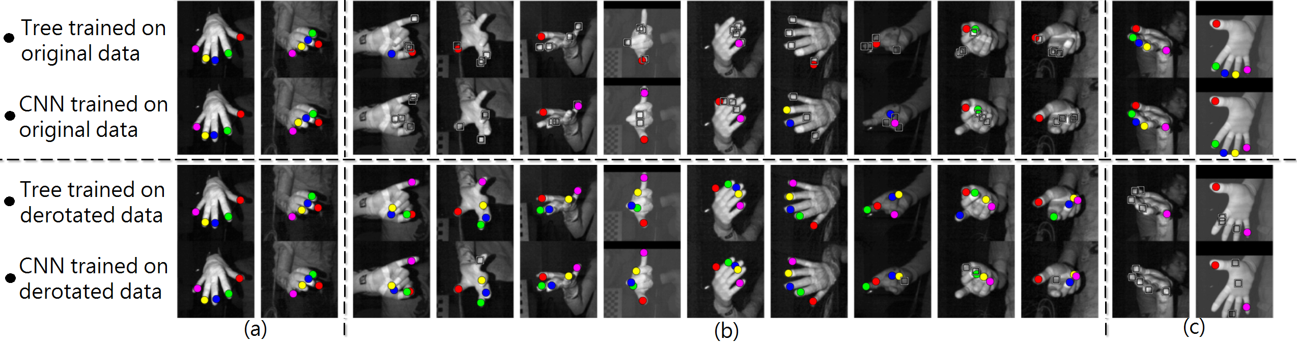
In this paper we propose a method for normalizing out the effects of rotation on highly articulated motion of deforming geometric surfaces such as hands observed by a depth camera. Changing the global rotation of an object directly increases the variation in appearance of the object parts. The work of [Kim et al.(2012)Kim, Hilliges, Izadi, Butler, Chen, Oikonomidis, and Olivier] physically removes this variability with a wristworn camera and samples only a single 3D point on each finger to perform full hand pose estimation. For markerless situations, removing variability through partial canonization can significantly reduce the space of possible images used for pose learning instead of trying to explicitly learn the variability through data augmentation. In [Lepetit et al.(2005)Lepetit, Lagger, and Fua] the authors show that learning a derotated 2D patch instead of the original one around a feature point dramatically reduces the learning capacity required and improves the classification results while using fewer randomized trees. To develop our method we use fingertip detection as a challenging representative scenario with a propensity for self occlusion and high rotational variability relative to an imaging sensor. Many approaches in the literature use fingertip or hand part detection towards the goal of full hand pose (e.g\bmvaOneDot[Keskin et al.(2013)Keskin, Kiraç, Kara, and Akarun],[Chen et al.(2014)Chen, Xiao, Yichen, Xiaoou, and Jian],[Tompson et al.(2014)Tompson, Stein, Lecun, and Perlin],[Wang and Popović(2009)]) however, they all approach the problem by trying to learn on datasets by augmenting rotational variability. Instead, we propose to remove this hand space variability during both the training phase and run-time. To this end we propose to learn the rotation using a deep convolutional neural network (CNN) in a regression context based on a network similar to that of [Tompson et al.(2014)Tompson, Stein, Lecun, and Perlin]. We show how this can be used to predict full three degrees of freedom (DOF) orientation information on a database of hand images captured by a depth sensor. We combine the predicted orientation with a novel in-plane derotation scheme. The "Rule of thumb" is derived from the following insight: there is almost always an in-plane rotation which can be applied to an image of the hand which forces the base of the thumb to be on the right side of the image. This implies that the ambiguity inherrent in rotationally variant features can be overcome by derotating the hand image to a canonical pose instead of augmenting a dataset with all variations of the rotational degrees of freedom as is commonly done. Figure 1 shows examples of extensive pose variation that can benefit from our approach 111All graphs and images in this paper are best viewed in color..
No currently available hand datasets (e.g\bmvaOneDot[Zhao et al.(2012)Zhao, Chai, and Xu],[Chen et al.(2014)Chen, Xiao, Yichen, Xiaoou, and Jian],[Tompson et al.(2014)Tompson, Stein, Lecun, and Perlin]) include accurate full 3 DOF ground truth hand orientations on a large database of real depth images. Using joint location data from NYUHands [Tompson et al.(2014)Tompson, Stein, Lecun, and Perlin] it is possible to extract a global hand orientation per pose. However, we found that the size of this dataset and rotational variability are not optimal for learning to predict 3 DOF orientation. A significant contribution of this paper is therefore the creation of a new, large-scale database of fully annotated depth images with 212928 unique hand poses captured by an Intel RealSense camera that we call HandNet222To advance research in the field this database and relevant code is available at www.cs.technion.ac.il/~twerd/HandNet/. For the purpose of effectively annotating such a large dataset we describe a novel image annotation technique. To overcome the severe occlusion inherrent in such a process we use DC magnetic trackers which are surprizingly sparsely used by the vision community considering their high accuracy, speed and robustness to occlusions. Using our deep derotation method (DeROT) we show up to 20.5% improvement in mean average precision (mAP) over our baseline results for two state-of-the-art approaches for fingertip detection in depth images, namely, a random decision tree [Keskin et al.(2013)Keskin, Kiraç, Kara, and Akarun] (RDT) and a deep convolutional neural network [Tompson et al.(2014)Tompson, Stein, Lecun, and Perlin] (CNN). We also compare our results to a non-learning based method similar to PCA and show that it produces inferior results, further supporting the proposed use of DeROT.
2 Building HandNet: Creation and annotation
Synthetic databases such as those created using [Šarić(2011)] have a severe disadvantage in that they cannot accurately account for natural hand motion, occlusions and noise characteristics of real depth cameras. The creation of a large hand pose database of real depth images with consistent annotations is therefore of great importance, but beyond the capability of human annotators. The NYUHands database [Tompson et al.(2014)Tompson, Stein, Lecun, and Perlin] uses a full model of the hand and a three-camera setup to annotate hand joint locations. There are instances where fingers are obstructed and accurate orientation information is not reliable. Similarly the method of [Wang and Popović(2009)] uses inverse kinematics coupled with a colored glove which also has the disadvantage of not having explicitly measured orientation as well as fingertip locations which are obstructed from the depth camera. An alternative to model based systems are sparse marker systems such as those used by [Zhao et al.(2012)Zhao, Chai, and Xu], however, the excessive cost of a modern mocap setup such as Vicon as well as the occlusion problem make such an approach unattractive. In contrast, modern DC magnetic trackers like the TrakStar [tra(2015)] are robust to metallic interference and obstruction by non-ferrous metals, and provide sub-millimeter and sub-degree accuracy for location and orientation relative to a fixed based station. Despite their almost non-existent use in modern computer vision literature, we have found them to be an excellent measurement and annotation tool.
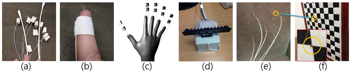
Sensors. To build and annotate our HandNet database we use a RealSense camera combined with TrakStar magnetic trackers. We affix the sensors to a user’s hand and fingertips by using tight elastic loops with sensors in sewn seam pockets. This prevents lateral and medial movement along the finger. This can be seen in Figure 2. The skin tight elastic loops have an additional significant benefit over gloves in that the depth profile and hand movements are not affected by the attached sensors and thus do not pollute the data.
Callibration. Camera callibration with known correspondences is a well studied problem [Zhang(1996)]. However, in our case we need to callibrate between a camera and a sensor frame. We do this by positioning the magnetic sensors on the corners of a checkerboard pattern thereby creating physical correspondence between the detected corner locations and the actual sensors. This setup can be seen in Figure 2. We use the extracted 2D locations of the corner points on the callibration board [Bouguet(2004)] together with the sampled sensor 3D locations to perform EPnP [Lepetit et al.(2009)Lepetit, Moreno-Noguer, and Fua] to determine the extrinsic configuration between the devices.
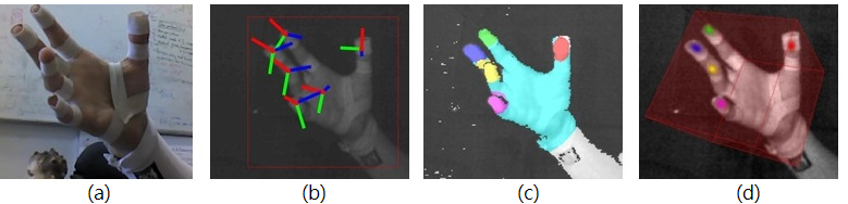
Annotation. We model each sensor as a 3D oriented ellipsoid. We then raycast the ellipsoid into the camera frame and set the label to be the identity of the ellipsoid closest to the camera for every pixel. We also create a heatmap for each fingertip using the same technique but setting the value per pixel to be gaussian over the distance to the projected sensor location. An example of both types of annotation can be seen in Figure 3.
Recording the database. The database is created from participants (half male, half female, different hand sizes) who perform random hand motions with extensive pose variation while wearing the magnetic sensors. The RealSense camera operates at fps producing depth maps which we reduce to . The TrakStar samples measurements at a rate of Hz. In total we recorded images. A portion of these images were removed because of low quality. The final dataset is frontal images including full annotation of the position and orientation of each fingertip and the back of the palm. After recording each participant we used a software utility to add offsets to the rotation and location of each sensor to adjust for greater consistency in positioning across subjects.
3 Fingertip detection
Although there are many non-learning based hand pose methods that can produce fingertip locations (e.g\bmvaOneDot[Schmidt et al.(2014)Schmidt, Newcombe, and Fox, Oikonomidis et al.(2011)Oikonomidis, Kyriazis, and Argyros, Melax et al.(2013)Melax, Keselman, and Orsten, Ballan et al.(2012)Ballan, Taneja, Gall, Gool, and Pollefeys]), they use kinematic and frame to frame constraints coupled with hand modelling. In contrast, here we specifically focus on per frame fingertip detection in depth images without either tracking or kinematic modelling. For our pipeline we first segment the target hand from the depth image using a fast depth based flood-fill method seeded either from the previous frame for real-time use and testing or from the ground truth hand location for building the database. Using the center of mass (CoM) of the segmented hand and its average depth value we define a depth dependent bounding box of size for a RealSense camera (HandNet) and for a Kinect camera (NYUHands) where is the depth of the CoM of the segmented hand. We derotate the image about the CoM using an angle of rotation according to the in-plane angle produced by DeROT described in Section 4. This comes from the predicted full 3D orientation at run-time or from the ground truth sensor orientation for database construction or testing. We then crop the image using the bounding box. We now describe our modifications of the two different, learning-based fingertip detectors that we use in this work.
3.1 Random decision tree
We follow the method of Keskin et al\bmvaOneDot[Keskin et al.(2013)Keskin, Kiraç, Kara, and Akarun] where a random decision tree (RDT) ensemble learns hand part labels for every pixel in a depth image of a hand. We refer the reader to the supplementary material of our paper as well as [Keskin et al.(2013)Keskin, Kiraç, Kara, and Akarun, Shotton et al.(2011)Shotton, Fitzgibbon, Cook, Sharp, Finocchio, Moore, Kipman, and Blake] for specific details of this approach. However, here we propose a number of key differences which we found specifically helpful for fingertip detection and run-time efficiency. We use the same random binary depth attributes per pixel but spatially distribute them according to an exponential sampling pattern similar to that of BRISK [Stefan et al.(2011)Stefan, Margarita, and Yves]. In addition to this, we use only a single RDT which contrasts with the common use of multiple trees in an ensemble. After training our single RDT the class distributions stored at each leaf can be used for inference because they represent the empirical estimate of the posterior probability of hand part label given the image evidence . Inferring the most likely fingertip identity label is therefore simply performed pixel-wise by finding the which maximizes per pixel. However, label inference performed this way results in noisy labels as neighboring classifications do not influence one another. Without adding more trees we propose a simple but highly effective spatial regularization: for each fingertip we treat the posterior for all pixels as an image and convolve it with a discrete 2D gaussian smoothing kernel with blur radius . This has the effect of correlating the posterior label distributions of nearby pixels. Therefore every pixel is labeled by fingertip identity (including palm and wrist labels) according to
| (1) |
Finally, we found that the close proximity of fingers compromises standard mean-shift [Comaniciu and Meer(2002)] clustering. Instead we detect the largest label blobs in the label image from Equation 1 above a certain area threshold. The 2D fingertip locations are then assigned to the blob centers and, if necessary, the average depth value for each blob can be used to generate the 3D camera-space coordinates.
Training the RDT. Training optimal decision trees is known to be NP-complete [Hyafil and Rivest(1976)] and therefore trees are built from the root down using breadth-first greedy optimization over tree node impurity. We use the Gini impurity measure which is slightly cheaper to compute than the more typical entropy measure. To build our database for training an RDT we extracted of the fingertip pixels in our training datasets and of the non-fingertip hand pixels. For HandNet this results in a training dataset of million sample pixels totaling GB of data for attributes. Our tree-builder trains an unpruned randomized tree on GTX 580 GPUs and an Intel I7 processor with GB of RAM in hours for a tree depth of with query tests per node. We are not aware of another single-workstation tree-builder capable of handling this quantity of data. The very large number of examples helps to prevent overfitting demonstrated by single RDTs.
3.2 Convolutional neural network
For our second evaluated method we build a CNN architecture based on Tompson et al\bmvaOneDot[Tompson et al.(2014)Tompson, Stein, Lecun, and Perlin] to predict the location of the five fingertips by using the maximum location in a set of heat maps which implicitly represent fingertip locations. We refer the reader to that work for specific details and to our supplementary material for the explicit architecture of our implementation. This multi-layer deep approach is critical for an input space as complicated as the set of images of an articulated object and we found that the deeper convolutional layers extract feature responses on a higher semantic level such as oriented fingertips. Using the heatmap based error objective helps to spatially regularize the network during training. For input to the CNN we set to be the cropped depth resized to pixels. We then downsample it by a factor of two twice to produce and . We use a subtractive form of local contrast normalization (LCN) [Tompson et al.(2014)Tompson, Stein, Lecun, and Perlin, Jarrett et al.(2009)Jarrett, Kavukcuoglu, Ranzato, and LeCun] so that using a gaussian smoothing kernel with pixels. The triplet is then input to the network. The trained network outputs a heatmap per fingertip for new data. Our method differs for fingertip detection in that we augment the output by a non-fingertip heatmap that is strong wherever a fingertip is not likely to be present. Also, instead of fitting a gaussian model to the strongest mode in the low resolution heatmaps, we instead upsample each fingertip heatmap to a fixed size of with a smoothing bi-linear interpolator. Similar to Section 3.1 every pixel is labeled with fingertip identity (including a non-fingertip class)
| (2) |
As in Section 3.1 the fingertip locations are given by the location of the largest label blob.
Training the CNN. Both the orientation regression CNN of the next Section as well as the described fingertip CNN are trained using Caffe [Jia et al.(2014)Jia, Shelhamer, Donahue, Karayev, Long, Girshick, Guadarrama, and Darrell] on an NVidia GTX 980 with an i7 processor and GB of onboard RAM. We train both with a Euclidean loss and a batch size of for iterations with stochastic gradient descent. We start with a learning rate of 0.01 and reduce it by a factor of 0.2 after every ten thousand iterations. We found that repeated fine-tuning was necessary to help network convergence.
4 Derotation
4.1 Orientation regression
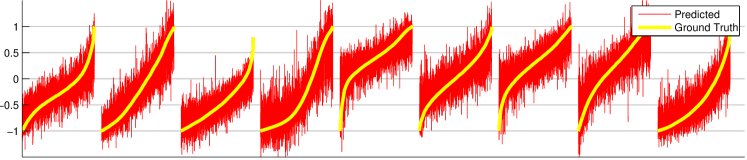
We adapt the deep convolutional architecture from Section 3 to predict full DOF hand orientation. Instead of a heatmap, we directly predict the coefficients of the rotation matrix. There are only degrees of freedom in a regular rotation but by using parameters and a large database we are effectively regularizing our over-parameterized output. The representation of a rotation matrix in this way is unique in unlike quaternions and Euler angles which we found to be noisy and unreliable. This noise was most visible when trying to predict a single representative angle. For training we use Euclidian loss and do not enforce orthonormality. However, the output of this CNN is directly projected onto the closest unitary matrix using the SVD decomposition . then provides a least squares optimal projection into , if we additionally enforce . Figure 5 shows the result of predicting the ground truth coefficients for HandNet and the full network architecture can be seen in the supplementary material.
4.2 DeROT: Designing a derotation method
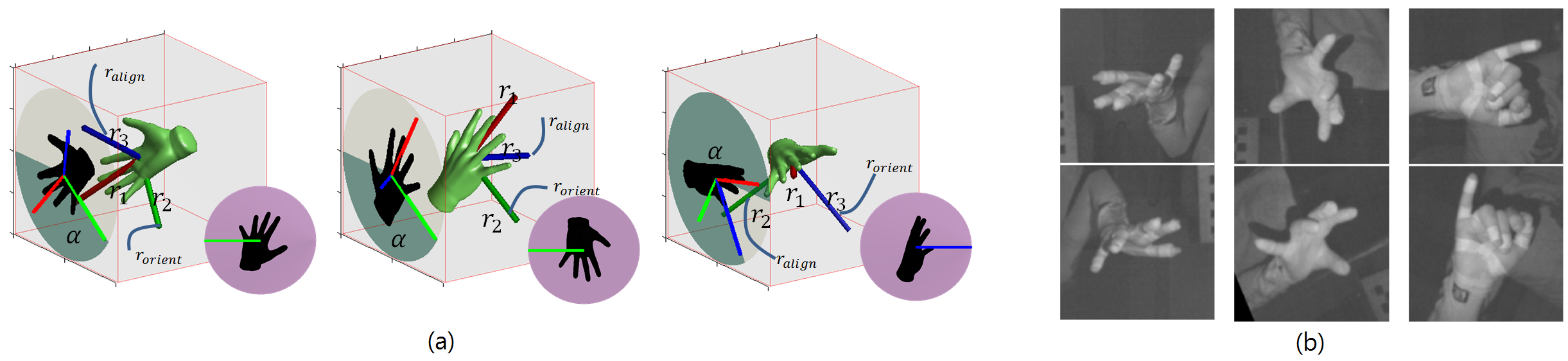
We take advantage of the orientation prediction to compute an angle which we will use for rotating the camera image about its center. The aim of this is to reduce pose variance by heuristically forcing the thumb to be on the right side of the image. We could use a predefined axis and set the angle with which to rotate the image to be that between the projection of this axis and the upwards image direction. Unfortunately, when this axis mostly points to or away from the camera the projection onto the screen will be small and noisy. As a simple heuristic we detect if this is the case and if so choose an alternative axis. Specifically we first determine the predicted axis most aligned with the camera z axis as . If is either the palm pointing direction or the direction of the extended fingers then we can be sure that the thumb direction will be non-noisy for this case and set . If the test yields instead that (i.e. thumb direction is mostly pointing towards or away from the camera) then we instead set which is the palm vector. This procedure is summarized in Algorithm 1. Synthetic and real examples can be seen in Figure 6. This choice is arbitrary and can be adapted for objects other than the hand. We thus define DeROT to be the combination of using the CNN from Section 4.1 to predict together with this derotation heuristic.
4.3 Derotation with PCA and Procrustes
Instead of using DeROT, an alternative approach is to extract the principal axes of the hand silhouette using PCA and taking the rotation angle of the largest axis to the vertical image axis. We have found that a similar but more stable option is to determine an enclosing ellipse using a Procrustes like algorithm on the convex hull of the points of the hand segmentation. The minimum area enclosing ellipse can be found efficiently over the points by minimizing for defining the ellipse. We solve this using Khachiyan’s algorithm [Aspvall and Stone(1980)]. However, as shown in Section 5.1 even with this added stability the method reduces performance rather than improving it.
5 Experiments
5.1 Evaluation protocol and data
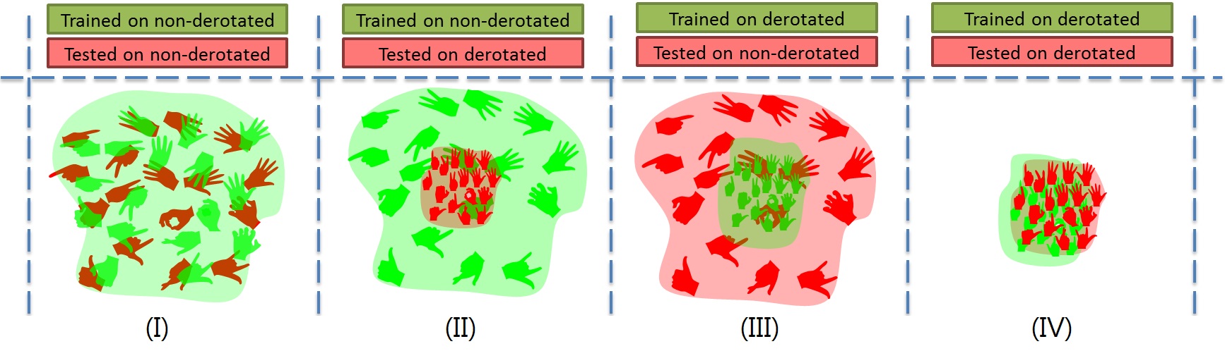
Experiments. We perform our experiments using our HandNet database and the publicly available database NYUHands [Tompson et al.(2014)Tompson, Stein, Lecun, and Perlin]. All experiments are performed separetly on the two databases. Our baseline results come from (I) training on non-derotated data and testing on non-derotated data. We compare this to (II) training on non-derotated data while testing with derotated data, (III) training on derotated data while testing with non-derotated data, (IV) training on derotated data while testing with derotated data.
Non-derotated data. For HandNet training we randomly select 202928 images and use the remaining 10000 images for testing. For NYUHands we use all 3 camera views (72757 images per view) for training and the frontal view for testing (8252 images). We slightly dilute the training and testing sets according to our hand segmentation pipeline which results in 184100 training images and 7241 testing images.
For experiment types (II) and (IV) we use this data to train two CNN orientation regression networks; one for each dataset. We use the same data for training the RDT and CNN fingertip detectors for experiment types (I) and (II). However, for testing the fingertip detectors in experiments (I) and (III), we rotate each testing image by uniformly random in-plane rotational offsets between - and degrees. This further guarantees that the testing data is different from the training data.
Derotated data. Experiment types (III) and (IV) use training data which is first derotated by an Oracle which we define to be DeROT that uses the ground truth obtained from the magnetic sensors. With experiment types (II) and (IV) we first apply the same uniform random image rotation to the test images exactly as for experiment types (I) and (II). We then apply one of the following: (a) Procrustes derotation, (b) DeROT using predicted by the CNN regression network, (c) Oracle derotation with .
Mean precision and mean average precision. We compute precision and recall according to the protocol of [Everingham et al.()Everingham, Gool, Winn, Williams, and Zisserman]. We set prediction confidence as the value at the location of the fingertip detection in the channel heatmap for each fingertip. The mean precision (mP) represents the mean precision over all fingertips at a recall rate of . Mean average precision (mAP) measures the mean of all the areas under the precision-recall curves for each fingertip and takes into account the behaviour over all confidence values.
Error threshold. The error of a prediction is the distance to the ground truth location. If a fingertip is more than 6 pixels from the ground truth position it is considered a false positive. The threshold of 6 pixels roughly translates into a distance of for both HandNet and NYUHands in an image patch of size cropped according to Section 3. is a natural threshold to choose as the distance between adjacent fingertips is over on average [Dandekar et al.(2003)Dandekar, Raju, and Srinivasan].
| Test set derotation method | None | (a) Procrustes | (b) DeROT | (c) Oracle |
|---|---|---|---|---|
| mP mAP | mP mAP | mP mAP | mP mAP | |
| HandNet | ||||
| RDT trained on non-derotated data | 0.51 0.79 | 0.49 0.77 | 0.55 0.85 | 0.60 0.87 |
| RDT trained on derotated data | 0.32 0.60 | 0.63 0.88 | 0.75 0.95 | |
| CNN trained on non-derotated data | 0.44 0.73 | 0.42 0.73 | 0.46 0.77 | 0.50 0.79 |
| CNN trained on derotated data | 0.30 0.59 | 0.61 0.88 | 0.74 0.95 | |
| NYUHands | ||||
| RDT trained on non-derotated data | 0.51 0.75 | 0.47 0.73 | 0.58 0.84 | 0.61 0.86 |
| RDT trained on derotated data | 0.35 0.58 | 0.63 0.88 | 0.68 0.89 | |
| CNN trained on non-derotated data | 0.38 0.70 | 0.36 0.69 | 0.46 0.80 | 0.48 0.81 |
| CNN trained on derotated data | 0.23 0.42 | 0.49 0.72 | 0.53 0.73 | |
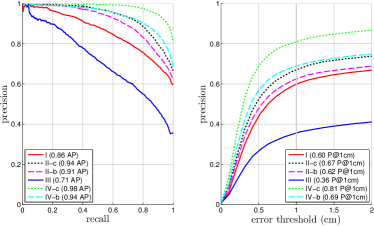
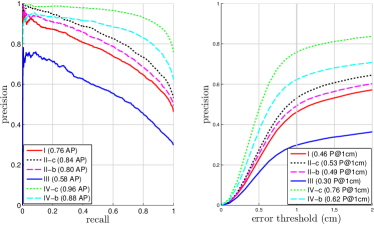
5.2 Discussion
The results of the experiments can be seen in Table 1. In Figure 7 we display a precision-recall curve and error threshold graph for the thumb on the HandNet test-set for all experiment types which is representative of the behavior of all fingertips. The results show that the use of DeROT improves over the baseline results for all measurements for both RDT and CNN for experiments on both datasets. On HandNet, when training an RDT and CNN on ground truth derotated data, we see that test-time use of DeROT yields improvement in mAP of 11.3% and 20.5% over the respective baselines. For NYUHands, DeROT gives an RDT a gain of 17.3% in mAP when trained on derotated data and a CNN achieves mAP gains of 14.2% when trained on underotated data but only a marginal gain of 2.5% when trained on derotated data. We found that the confidence values for this specific case were not reliable (which directly effects mAP) because of confusion between fingertips (specifically index and ring) which further justified the creation of HandNet. For all experiments and datasets the mP when using DeROT shows improvements of between 7.8% and 21.1% on underotated training data and between 23.5% and 38.6% for derotated training data. The simplistic Procrustes derotation negatively impacts fingertip detection relative to the baseline and we therefore chose not to build and train an RDT and CNN on Procrustes derotated versions of the two datasets. For our experiments a single RDT mostly outperforms a CNN. Although they are trained with different data and objectives it hints that there is no silver bullet to determining which machine learning approach is more appropriate.
6 Conclusions and future work
We have shown that using derotation, specifically DeROT, significantly improves the localization ability of machine-learning based per-frame fingertip detectors by reducing the variance of the pose space. Furthermore we find that this procedure works despite the extremely high range of potential poses. We see this approach as an alternative to data augmentation and as a potentially useful additional step in pipelines dedicated to articulated object pose extraction such as hands. Although we have used no prior model or kinematic constraints to improve the detection results this is currently an active area that we are investigating. Also, in this work we have considered results only on depth images but it would be interesting to apply a similar pipeline to pure 2D color images.
Acknowledgments
This research was supported by European Community’s FP7- ERC program, grant agreement no. 267414.
References
- [tra(2015)] Ascension TrakStar. http://www.ascension-tech.com/, 2015.
- [Aspvall and Stone(1980)] B. Aspvall and R. Stone. Khachiyan’s linear programming algorithm. pages 1–13, 1980.
- [Ballan et al.(2012)Ballan, Taneja, Gall, Gool, and Pollefeys] L. Ballan, A. Taneja, J. Gall, L. Van Gool, and M. Pollefeys. Motion capture of hands in action using discriminative salient points. In European Conference on Computer Vision (ECCV), Firenze, October 2012.
- [Bouguet(2004)] J. Bouguet. Camera calibration toolbox for matlab. 2004.
- [Chen et al.(2014)Chen, Xiao, Yichen, Xiaoou, and Jian] Q. Chen, S. Xiao, W. Yichen, T. Xiaoou, and S. Jian. Realtime and robust hand tracking from depth. In Conference on Computer Vision and Pattern Recognition (CVPR), pages 1106–1113. IEEE, 2014.
- [Comaniciu and Meer(2002)] D. Comaniciu and P. Meer. Mean shift: A robust approach toward feature space analysis. Transactions on Pattern Analysis and Machine Intelligence, 24:603–619, 2002.
- [Dandekar et al.(2003)Dandekar, Raju, and Srinivasan] K. Dandekar, B. Raju, and M. Srinivasan. 3-d finite-element models of human and monkey fingertips to investigate the mechanics of tactile sense. Journal of biomechanical engineering, 125:682–691, 2003.
- [Everingham et al.()Everingham, Gool, Winn, Williams, and Zisserman] M. Everingham, L. Van Gool, J. Winn, C. Williams, and A. Zisserman. The PASCAL Visual Object Classes Challenge 2011 (VOC2011) Results. http://www.pascal-network.org/challenges/VOC/voc2011/workshop/index.html.
- [Hyafil and Rivest(1976)] L. Hyafil and R. Rivest. Constructing optimal binary decision trees is np-complete. Information Processing Letters, 5:15–17, 1976.
- [Jarrett et al.(2009)Jarrett, Kavukcuoglu, Ranzato, and LeCun] K. Jarrett, K. Kavukcuoglu, M. Ranzato, and Y. LeCun. What is the best multi-stage architecture for object recognition? In International Conference on Computer Vision (ICCV), pages 2146–2153. IEEE, 2009.
- [Jia et al.(2014)Jia, Shelhamer, Donahue, Karayev, Long, Girshick, Guadarrama, and Darrell] Y. Jia, E. Shelhamer, J. Donahue, S. Karayev, J. Long, R. Girshick, S. Guadarrama, and T. Darrell. Caffe: Convolutional architecture for fast feature embedding. arXiv preprint arXiv:1408.5093, 2014.
- [Keskin et al.(2013)Keskin, Kiraç, Kara, and Akarun] C. Keskin, F. Kiraç, Y. Emre Kara, and L. Akarun. Real time hand pose estimation using depth sensors. In Consumer Depth Cameras for Computer Vision, pages 119–137. Springer, 2013.
- [Kim et al.(2012)Kim, Hilliges, Izadi, Butler, Chen, Oikonomidis, and Olivier] D. Kim, O. Hilliges, S. Izadi, A. Butler, J. Chen, I. Oikonomidis, and P. Olivier. Digits: freehand 3d interactions anywhere using a wrist-worn gloveless sensor. In Proceedings of the symposium on User interface software and technology (UIST), pages 167–176. ACM, 2012.
- [Lepetit et al.(2005)Lepetit, Lagger, and Fua] V. Lepetit, P. Lagger, and P. Fua. Randomized trees for real-time keypoint recognition. In Conference on Computer Vision and Pattern Recognition (CVPR), pages 775–781, 2005.
- [Lepetit et al.(2009)Lepetit, Moreno-Noguer, and Fua] V. Lepetit, F. Moreno-Noguer, and P. Fua. E-pnp: An accurate o(n) solution to the pnp problem. International journal of computer vision, pages 155–166, 2009.
- [Melax et al.(2013)Melax, Keselman, and Orsten] S. Melax, L. Keselman, and S. Orsten. Dynamics based 3d skeletal hand tracking. In I3D, page 184, 2013.
- [Oikonomidis et al.(2011)Oikonomidis, Kyriazis, and Argyros] I. Oikonomidis, N. Kyriazis, and A. Argyros. Markerless and efficient 26-dof hand pose recovery. In Asian Conference on Computer Vision (ACCV), pages 744–757. 2011.
- [Schmidt et al.(2014)Schmidt, Newcombe, and Fox] T. Schmidt, R. Newcombe, and D. Fox. Dart: Dense articulated real-time tracking. Proceedings of Robotics: Science and Systems, Berkeley, USA, 2014.
- [Shotton et al.(2011)Shotton, Fitzgibbon, Cook, Sharp, Finocchio, Moore, Kipman, and Blake] J. Shotton, A. Fitzgibbon, M. Cook, T. Sharp, M. Finocchio, R. Moore, A. Kipman, and A. Blake. Real-time human pose recognition in parts from single depth images. In Conference on Computer Vision and Pattern Recognition (CVPR), pages 1297–1304, 2011.
- [Stefan et al.(2011)Stefan, Margarita, and Yves] L. Stefan, C. Margarita, and S. Roland Yves. Brisk: Binary robust invariant scalable keypoints. In International Conference on Computer Vision (ICCV), pages 2548–2555. IEEE, 2011.
- [Tompson et al.(2014)Tompson, Stein, Lecun, and Perlin] J. Tompson, M. Stein, Y. Lecun, and K. Perlin. Real-time continuous pose recovery of human hands using convolutional networks. ACM Transactions on Graphics (TOC), 33, 2014.
- [Šarić(2011)] M. Šarić. Libhand: A library for hand articulation, 2011. URL http://www.libhand.org/.
- [Wang and Popović(2009)] R. Wang and J. Popović. Real-time hand-tracking with a color glove. ACM transactions on graphics (TOG), 28(3), 2009.
- [Zhang(1996)] Z. Zhang. On the epipolar geometry between two images with lens distortion. In Proceedings of: International Conference on Pattern Recognition (ICPR), pages 407–411, 1996.
- [Zhao et al.(2012)Zhao, Chai, and Xu] W. Zhao, J. Chai, and Y. Xu. Combining marker-based mocap and rgb-d camera for acquiring high-fidelity hand motion data. In Symposium on Computer Animation, pages 33–42, 2012.