Irina Afanasieva
Data Acquisition and Control System for High-Performance Large-Area CCD Systems
Abstract
Astronomical CCD systems based on second-generation DINACON controllers were developed at the SAO RAS Advanced Design Laboratory more than seven years ago and since then have been in constant operation at the 6-meter and Zeiss-1000 telescopes. Such systems use monolithic large-area CCDs. We describe the software developed for the control of a family of large-area CCD systems equipped with a DINACON-II controller. The software suite serves for acquisition, primary reduction, visualization, and storage of video data, and also for the control, setup, and diagnostics of the CCD system.
1 INTRODUCTION
The Advanced Design Laboratory of the Special Astrophysical Observatory of the Russian Academy of Sciences develops and makes CCD systems (CCD-based digital image acquisition systems) for the Eurasia’s largest 6-m telescope and other optical telescopes. The system (Markelov et al., 2000) consists of a CCD array detector, incorporated into a cryostatic camera, and a CCD controller with an interface for digital data input into a remote control computer (the host computer). We now focus on image acquisition systems equipped with the E2V CCD 42-40 (20482048 pixels) and E2V CCD 42-90 (20484608 pixels) detectors. The data are fed to the control computer via a 100 Mbit standard Ethernet unit. The software required for the control of the CCD system and acquisition of astronomical data (images) should be reliable, ensure high throughput, and provide tools for setup and diagnostics of the data acquisition system. Object-oriented methodologies and developing and debugging tools (Gomaa, 2000) allow rapid development of such software suites.
2 ARCHITECTURE OF THE DATA ACQUISITION SYSTEM
The development of the program was carried out in line with the requirements it was supposed to meet. The acquisition system is to be able to perform the following functions:
-
•
provide interface between the user and the CCD system;
-
•
run the controller;
-
•
ensure data acquisition and storage;
-
•
visualize and analyze the data;
-
•
perform setup, telemetry, and diagnostics of the CCD system;
-
•
test the photoelectric characteristics of the CCD system.
The system should also allow programmable setting of the integration and readout parameters including:
-
•
exposure time;
-
•
shutter control parameters;
-
•
parameters of detector flushing before charge integration;
-
•
image readout speed;
-
•
number of the detector output node;
-
•
size and coordinates of the region of interest (ROI) to read;
-
•
binning factor along the two coordinates;
-
•
video channel gain;
-
•
exposure mode (frame-by-frame, combined, scanning).
The program architecture should combine end-user requirements with technical specifications via understanding of the use cases with subsequent finding of the ways of their implementation (Maciaszek, 2001).
We formulated the main quality criteria to be met by the architecture of the acquisition and control system:
-
•
universality, the ability to adapt to controlling CCDs of various types used in astronomy and to interact with various digital data input interfaces;
-
•
flexibility, implementation of all integration and readout modes that are possible for the detector of the type considered, full programmability of CCD control parameters: voltage levels, clock sweeps, time base, and detector temperature, and their telemetric control;
-
•
efficiency, minimum image readout, recording, analysis, and visualization times, synchronization of data exchange streams, ensuring the efficient work of the operator in the process of data acquisition, and operation of the facility in the mode of interacting concurrent tasks;
-
•
adaptability, implementation of different observing methods with the possibility of connecting and controlling of external devices (shutter, filters) from within the acquisition system;
-
•
usability, development of a unified and intuitive user interface with an extended structure of menus, dialog boxes, and graphical windows; distributing functions among subsystems, minimization of data flows between them, possibility of automating the observing process.
The proposed software architecture (Fig. 1) is based on the client/server model, which meets the operation efficiency and reliability requirements (Menasce & H. Gomaa, 2000; Lesser & M. Parthasarathy, 2004; Bonati & M. Ashe, 2004) and has prospects for future development. The server directly interacts with the detecting system, however, the actual control is performed by the clients, which can connect to the server.
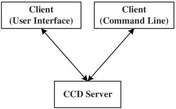
The server and client parts of the system can be hosted on different physical nodes using network programming technologies or special client-server interaction middleware. For convenience, let us refer to clients of the first and second type as graphical and symbolic respectively. The functions to be performed by the server part include:
-
•
initialization of the CCD system, implementation of various exposure modes;
-
•
setup, testing, and diagnostics of the CCD system;
-
•
interaction with the interface board (Ethernet adapter), synchronization of reception and transmission of IEEE 802.3 network packets;
-
•
interaction with clients, synchronization of the acquisition of commands and transmission of the results of their execution;
-
•
formation and recording of image files.
Functions of the graphical client:
-
•
graphical user interface;
-
•
interactive control of the CCD system;
-
•
interface for connecting to and controlling external devices (shutter, filters);
-
•
setting various observing methods;
-
•
setting and telemetric control of the detector voltage levels and temperature;
-
•
interactive control of the interface board.
Functions of the symbolic client:
-
•
control of the CCD system from a command line or a batch file.
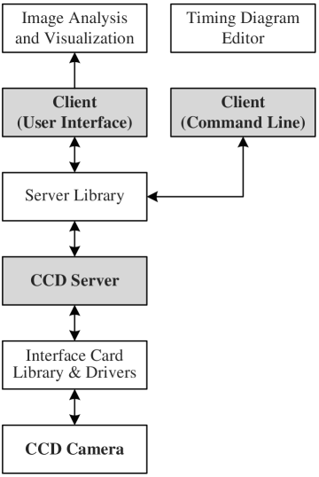
Visualization of images and editing of time base diagrams can be implemented in separate applications and used independently of the server and clients.
Let us now define more exactly the resulting architecture by subdividing it into units (Fig. 2). Here by a unit we mean a set of closely interconnected classes and/or objects, subsystems, dependences, operations, events, and constraints together with a sufficiently well-defined and, as far as possible, compact interface with other units.
We use the UML language (Fowler & K. Scott, 1997) to create classes and objects and describe the processes and architecture of the software suite. See our earlier paper for the justification of this choice (Afanasieva, 2010).
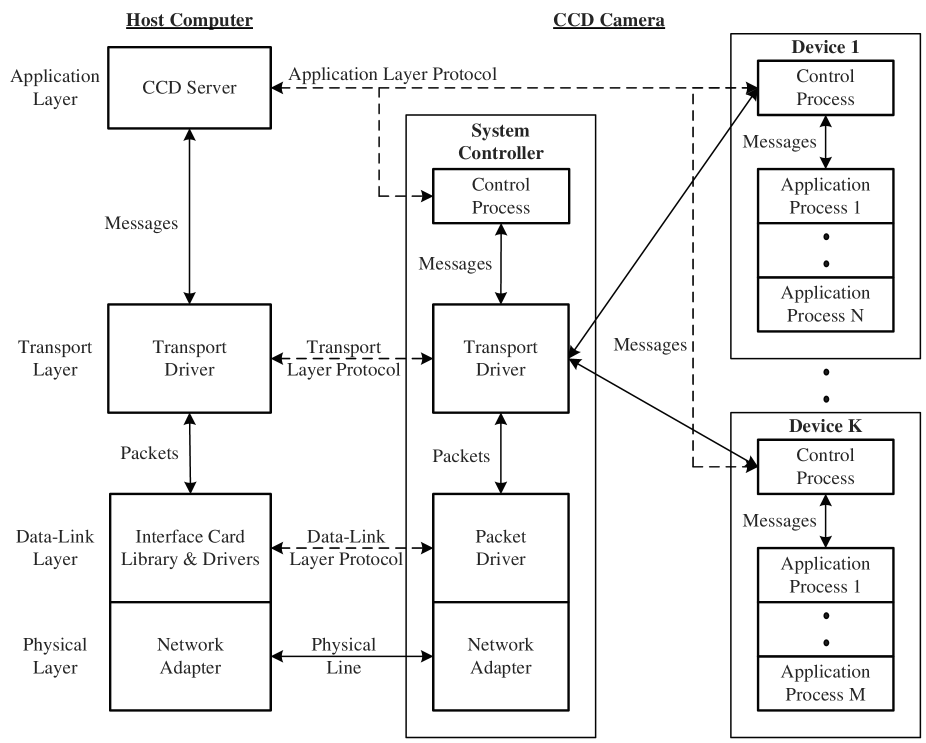
Let us now consider in more detail the data exchange between the server and the CCD controller. Because of the need for data exchange between the control process in the host computer and application processes in the controller, the underlying principles resemble those of the corresponding network exchange processes in many respects. Four layers of the Open Systems Interconnection (OSI) model (GOST R ISO/MEK, 1999) are used to create the interface with the CCD system. The choice of the required layers is determined by the configuration of the data links in the CCD system, performance and reliability requirements. The upper (application) layer ensures independent message exchange between various processes in the controller on the one part and the host computer on the other part. The interaction between the CCD server and the controller should occur on two (application and transport) layers. The physical layer and a part of the data link layer are hardware implemented in the network adapter. Figure 3 shows the network interface hierarchy. Data exchange occurs through a fiber-optical link via an Ethernet adapter using the WinPCAP low-level library for interaction with network device drivers.111http://www.winpcap.org/docs/docs 412/
At the application layer, the processes exchange messages. Messages sent by the host computer to the controller contain asynchronous control commands, which may include the necessary data. In the opposite direction data-containing messages (which include information about the state of the controller) and service requests are sent. In addition to asynchronous control commands, the controller also executes synchronous commands that are passed to it in advance in the form of a data array.
Asynchronous control commands can be subdivided into the following groups:
-
•
status poll command;
-
•
power on/off and reset commands;
-
•
data array exchange commands;
-
•
commands for the start/stop of controller processes;
-
•
host computer and controller synchronization commands;
-
•
command of asynchronous control of external devices.
Synchronous commands include the following groups:
-
•
commands of the synchronous control of charge integration/transfer;
-
•
synchronous readout control commands;
-
•
commands of synchronous control of external devices;
-
•
instruction execution sequence control command.
At the transport layer the computer and CCD controller exchange Ethernet IEEE 802.3 packets(frames). The following commands provide the interface between the transport and application layers:
-
•
connect (TransportConnect);
-
•
disconnect (TransportDisconnect);
-
•
write message (TransportWriteMsg);
-
•
read message (TransportReadMsg);
-
•
read transport status (TransportStatus);
-
•
reset transport level (TransportReset).
Given that the clients and the server are independently running applications, a proper interprocess communication (IPC) method should be chosen. We use a very simple an easy-to-implement data streaming method—a named pipe, i.e., a dedicated data link connecting the two processes. One of the processes creates the channel and the other one opens it, after which both processes can send the data via this channel in one or both directions using file read/write functions. This method makes it possible to organize data exchange both between the local processes and between processes started on different network nodes. Client commands can be of two types: serving for (1) the interaction with the server exclusively (information commands) and (2) for the interaction with the controller. The data of the commands of the first type are sent via channels C_PIPE_INFO (read) and S_PIPE_INFO (write), and those of the commands of the second type—via channels C_PIPE (read) and S_PIPE (write). All channels are created by the server. Applications use semaphores, critical sections, mutexes, queues, and messages for synchronizing tasks and intertask data exchange.
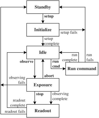
The main characteristic of the CCD server is its control state, which identifies the working program segment and corresponds to the current state of the CCD system. The server is in the initial state (Standby) when it starts. The system considered has a total of six control states (Fig. 4). Transitions between the states are triggered by client commands (setup, observe, stop, abort, and run cmd).
3 USER INTERFACE AND CAPABILITIES OF THE SYSTEM
The software suite that we developed runs in the Windows XP operating system, has a convenient and intuitive user interface and an extended menu system. Its multimodule and multitask architecture allows the astronomer to perform several tasks simultaneously both in the interactive and automatic modes. The graphical client provides the following control and telemetry windows:
-
•
Exposure Control, to control the CCD system;
-
•
Temperature, for the setup and telemetry of the detector temperature;
-
•
Wave Levels, for the setup and telemetry of detector clock levels;
-
•
Output Node Levels, for the setup and telemetry of the working voltages and currents of the output stages of the detector.
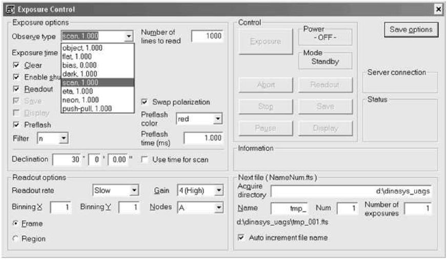
The Exposure Control dialog box (Fig. 5) allows the user to efficiently control the detector, select various image integration and readout methods, and set the exposure parameters. It is used to set the following parameters: exposure type, integration time, flag of detector flushing before integration, shutter flag, number of the filter, readout speed, binning ratio along the two coordinates, video channel gain, output nodes of the detector, size and coordinates of the ROI to read, number of exposures, parameters of visualization and writing to a file. This dialog box also displays information about the progress of command execution, the controller power and control states. Acquisition of images with different readout speeds reduces substantially the time spent to prepare the system for observations. Data acquisition can be started after successful initialization of the CCD system. Exposure starts with a click of the Exposure button. After integration the data are digitized, transferred to the computer, and written to a file on the disk.
The observer can choose from the following exposure types:
-
•
bias, the signal is read from the CCD and then digitized without counting time and opening the shutter;
-
•
dark, the charge is accumulated during predetermined time interval, the signal is read from the CCD and digitized, the shutter is not opened;
-
•
object, integration and readout in the frame-by-frame mode; the shutter is opened, charge is accumulated during certain time interval, the shutter is closed, the signal is read from the CCD and digitized;
-
•
neon, the selected filter is installed, the comparison spectrum lamp is switched on, the shutter is opened, charge is accumulated over a certain time interval, the comparison spectrum lamp is switched off, the signal is read from the CCD and digitized;
-
•
scan, integration and readout proceed in the drift-scan mode; the shutter is opened, the first data row of the CCD is read and digitized, after certain time the second row is read and so the given number of rows are read one by one, and the shutter is closed; the drift-scan mode allows long observations of sky objects to be performed;
-
•
push-pull, the combined integration and transfer mode (Chountonov et al., 2000); in addition to standard exposure parameters, the user sets the elementary exposure time, number of transfers, and the number of rows by which the image is transferred.
The built-in plug-in mechanism allows any additional devices (filter turrets, comparison spectrum lamps, etc.) to be connected to the CCD system. A full-blown internal batch-programming macro language allows automating individual processes of the control of image integration, readout, and visualization. The system also provides:
-
•
a data acquisition function for computing the transformation quantum and readout noise of video channels;
-
•
a data acquisition function for measurement the noise spectra of the video channel in order to determine the coefficients of the optimum filter used during real-time digital video processing in the video channel;
-
•
a function for the acquisition of the transfer characteristic of video channels for its subsequent digital correction in order to stabilize and linearize it.
4 CONCLUSIONS
A data acquisition system for optical observations on the 6-meter and Zeiss-1000 telescopes has been developed, implemented, and is currently supported at the Special Astrophysical Observatory. While in operation, the system proved its relevance and efficiency. It ensures data acquisition, recording, primary reduction, and visualization. We have implemented the important functionality of automating the observing process and the control of CCD system parameters during observations.
Acknowledgements.
This work was supported in part by theRussian Foundation for Basic Research (grantNo. 08-07-12099) and the Division of Physical Sciences of the Russian Academy of Sciences (the program Extended Objects in the Universe). I am grateful to all my colleagues who took part in discussing this work. Observations on the 6-m telescope are supported by the Ministry of Educationand Science of the Russian Federation(contract No. 14.619.21.0004, project identifierRFMEFI61914X0004).References
- Afanasieva (2010) I. V. Afanasieva, Obozrenie Prikladnoi i Promyshlennoi Matematiki 18 (1), 162 (2010).
- Bonati & M. Ashe (2004) M. Bonati and M. Ashe, in Scientific Detectors for Astronomy: The Beginning of a New Era, Ed. by P. Amico, J. W. Beletic and J. E. Beletic (Kluwer Academic Publishers, Dordrecht, 2004), p. 427.
- Chountonov et al. (2000) G. A. Chountonov, V. A. Murzin, N. G. Ivashchenko, and I. V. Afanasieva, in Magnetic Fields of Chemically Peculiar and Related Stars, Ed. by Yu. V. Glagolevskij and I. I. Romanyuk (2000), p. 249.
- Fowler & K. Scott (1997) M. Fowler and K. Scott, UML Distilled: Applying the Standard Object Modeling Language (Addison-Wesley, 1997).
- Gomaa (2000) H. Gomaa, Designing Concurrent, Distributed, and Real-Time Applications with UML (Addison-Wesley, Boston, 2000).
- GOST R ISO/MEK (1999) GOST R ISO/MEK 7498-1-99, Informatsionnaya tekhnologiya. Vzaimosvyaz otkrytykh sistem. Bazovaya etalonnaya model (Izdatelstvo standartov, Moscow, 1999).
- Lesser & M. Parthasarathy (2004) M. Lesser and M. Parthasarathy, in Scientific Detectors for Astronomy: The Beginning of a New Era, Ed. by P. Amico, J. W. Beletic, and J. E. Beletic (Kluwer Academic Publishers, Dordrecht, 2004), p. 445.
- Maciaszek (2001) L. A. Maciaszek, Requirements Analysis and System Design: Developing Information Systems with UML (Addison-Wesley, Harlow, 2001).
- Markelov et al. (2000) S. V. Markelov, V. A. Murzin, A. N. Borisenko, et al., Astron. Astrophys. Transactions 19, 579 (2000).
- Menasce & H. Gomaa (2000) D. A. Menasce and H. Gomaa, IEEE Transactions on Software Engineering 26, 1066 (2000).