Free energy cost of forming an interface between a crystal and its frozen version
Abstract
Using a thermodynamic integration scheme, we compute the free energy cost per unit area, , of forming an interface between a crystal and a frozen structured wall, formed by particles frozen into the same equilibrium structure as the crystal. Even though the structure and potential energy of the crystalline phase in the vicinity of the wall is same as in the bulk, has a non-zero value and increases with increasing density of the crystal and the wall. Investigating the effect of several interaction potentials between the particles, we observe a positive at all crystalline densities if the potential is purely repulsive. For models with attractive interactions, such as the Lennard-Jones potential, a negative value for is obtained at low densities.
I Introduction
The excess free energy of a crystal in contact with a wall is an important quantity governing many interfacial phenomena such as wetting and heterogeneous nucleation degennes85 ; zettlemoyer69 ; abraham74 ; kashchiev00 ; adamson97 . Theoretical approaches based on cell theory have been used to compute this quantity for model systems such as hard spheres heni-loewen99 . Atomistic simulation studies have also been carried out employing widely-used interaction potentials such as Lennard-Jones (LJ) models and systems of hard spheres heni-loewen99 ; benjamin-horbach2012 ; benjamin-horbach2013_1 ; benjamin-horbach2013_2 ; fort-djik06 ; laird07 .
In most previous studies, the crystal is either in contact with a flat structureless wall heni-loewen99 ; fort-djik06 ; laird07 or a structured wall consisting of particles attached to sites corresponding to an ideal crystalline structure benjamin-horbach2012 . In both of these situations, the structure and energy of the crystalline layers in the neighborhood of the wall is not the same as in the bulk leading to an excess free energy as compared to the bulk.
An interesting situation arises when the energy and structure of the crystalline layers in contact with the wall remains the same as in the bulk. Such a scenario occurs when the wall consists of particles frozen into positions occupied by the same crystalline phase at equilibrium. In this case, the wall is a frozen version of the same crystal. Then, it is of interest from a fundamental statistical mechanical point of view, to determine the excess free energy of the system in comparison to the bulk.
An analogous situation corresponding to a supercooled liquid in contact with a wall consisting of particles frozen into the same amorphous structure as the liquid has been widely studied in recent years in order to investigate the relaxation dynamics of glass-forming systems krackoviak ; scheidler2004 ; scheidler_epl2002 ; berthier2012 ; cavagna2012 ; gradenigo2013 ; kobnaturephys ; cammarota2012 . Recently, an experimental investigation of such a system was carried out using colloidal particles sood2015 . Such computational and experimental studies extract a growing length scale based on a slowing down of the dynamics near the wall and relate it to the slowing down of glassy dynamics in the bulk. In these investigations, it is implicitly assumed that the thermodynamics of the system is unperturbed by the wall if an average is carried out over the thermal fluctuations and different realizations of the wall scheidler2004 ; berthier2012 . However, in a recent work we obtained a non-zero interfacial free energy for a glass-forming binary Lennard-Jones liquid kob-andersen-1995 in contact with a wall with the same amorphous structure as the supercooled liquid, indicating that thermodynamics of the liquid is affected by the presence of such a frozen wall benjamin-horbachpre .
In this work, we compute the excess free energy of a crystal in contact with a wall formed by its frozen version, using molecular dynamics simulations allen-tildesley87 in conjunction with thermodynamic integration frenkel-smit02 . We obtained a non-zero interfacial free energy for particles interacting via a Lennard-Jones potential benjamin-horbach2014 , which increases with increasing density of the crystal suggesting that the thermodynamics of the crystal in contact with such a wall is perturbed and not the same as in the bulk. Moreover, at low densities is negative, indicating an increase of entropy as compared to the bulk. To test the robustness of our results and find out whether a negative value of is model-dependent or not, we carried out investigations with two other interaction potentials: a purely repulsive inverse-twelfth power soft-sphere potential and the hard sphere interaction (using a potential) benjamin-horbach2015 . However, for the two purely repulsive interactions, while non-zero, is positive at all crystal densities.
In the next section we specify the interaction potentials considered in this work. In section III, the system is described and then we outline the thermodynamic integration scheme adopted to compute . In section V, we describe the simulation details and then present our results in section VI. Finally, we end with a conclusion.
II Interaction Potentials
In order to study the robustness of our findings, we obtained corresponding to three different interaction potentials. The interaction potentials are denoted by [], being the distance between the particles. Energies and lengths are expressed in units of the parameters and , respectively (see below), and the masses of the particles are set to . In the following, all other quantities are given in terms of the latter parameters, i.e. time in units of , pressure in units of , and the interfacial free energy in units of .
The following interaction potentials are considered in this work:
(i) A modified Lennard-Jones interaction potential (mLJ) is chosen, defined by
| (1) |
with
| (2) |
for , and
| (3) |
for and for . The constants in Eqs. (1) and (3) are given by , , , , and .
(ii) The second potential we consider is the purely repulsive force-shifted inverse-twelfth power potential (fsi12),
| (4) |
where, . Here, the potential is truncated and shifted such that and its derivative with respect to goes to zero at .
(iii) The third potential is a hard-sphere interaction modeled by a inverse-power potential (i256):
| (5) |
The potential is cut off at . As shown previously benjamin-horbach2015 , the coexistence and other bulk properties of this interaction potential are very similar to those of the hard-sphere system.
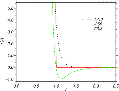
In Fig. 1, we show the three interaction potentials as a function of the distance between the particles.
III System Setup
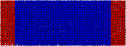
Our systems consist of face centered cubic (fcc) crystals of particles, with the (100) face oriented along the direction, enclosed in a simulation box of dimension . Periodic boundary conditions are maintained along the and directions. Along the direction, the particles are confined by several layers of the same crystalline particles frozen into their equilibrium configuration (see Fig. 2). Since there are two wall-crystal interfaces, the total area of the interface is . In order to prevent any crystalline particle from penetrating the wall, a short-ranged flat wall, modeled by a Gaussian potential is inserted at the boundaries along the direction (at and ). As shown in our earlier works benjamin-horbach2014 ; benjamin-horbach2015 , such a short-ranged flat wall leads to a negligible contribution to the interfacial free energy ().
IV Thermodynamic Integration
The interfacial free energy is defined as , where is the free energy of the crystal confined by the frozen walls on both sides, while is the free-energy of the bulk crystal with periodic boundary conditions along all the three Cartesian axes. Our objective is to compute using molecular dynamics simulation and thermodynamic integration.
The thermodynamic integration scheme adopted in this work is based on a similar approach devised by us in previous studies to compute the interfacial free energy of a liquid/crystal in contact with structured walls benjamin-horbach2012 ; benjamin-horbach2013_1 ; benjamin-horbach2013_2 and to determine the crystal-liquid interfacial free energy benjamin-horbach2014 ; benjamin-horbach2015 . The goal is to transform a bulk crystal with periodic boundaries in all three Cartesian-axes directions into a crystal in contact with frozen crystalline layers comprising the frozen walls on either side. To accomplish this, it is neccessary that the boundary conditions along the direction are rearranged at some point during the transformation and that the crystalline particles do not cross the boundaries during this rearrangement. Hence, in the first step, two extremely short-ranged flat walls, modeled by a Gaussian potential and denoted by , are gradually inserted at the boundaries of the simulation box at and with periodic boundary conditions maintained along all three axes. Since the structureless flat wall has a very short range (), few crystalline particles interact with it. As a result, the contribution of this step to the total interfacial free energy is negligible and does not affect the structure of the crystal near the walls. To integrate the equations of motion in molecular dynamics in presence of such extremely short ranged walls, a very small time-step is needed. This reduces the computational efficiency since the other forces in the simulation such as those between the crystalline particles are more comparatively long-ranged (). However, by the use of a multiple time-step scheme frenkel-smit02 ; benjamin-horbach2014 ; benjamin-horbach2015 , the computational overhead is reduced significantly and our simulations are slightly less than two times slower than those carried out with a single large time-step.
In the second step, interactions of particles through the periodic boundaries along the direction are gradually switched off while interactions between the crystal and the frozen crystalline wall are gradually switched on, in presence of the flat walls. The final state is a crystal with periodic boundaries along the and axes and confined by frozen crystalline walls and the flat walls along the direction. Since the free-energy difference per unit area corresponding to the first step is negligible the total contribution to comes only from the second step.
In the TI scheme adopted in this work, similar to our earlier works, the transformation from one state to the next is brought about by changing a switching parameter , which couples to the interaction potential between the walls and the crystalline particles. The TI scheme consists of two steps. In step 1, the dependent Hamiltonian has the form , where , with and . By switching from to , the system is transformed from a pure bulk crystal (, no wall), to a crystal in contact with an extremely short-ranged Gaussian flat wall (). In step 2, the -dependent part of the Hamiltonian has different forms for the different interaction potentials. For the LJ and inverse-twelfth power potentials, , while for the hard-sphere potential, . Here, represents interactions between the crystalline particles through the periodic boundaries, while denotes the interaction between a crystal and a frozen wall particle and is identical to the interaction between two crystalline particles. In the second step, corresponds to the crystal in contact only with a flat wall, while at the crystal is in contact with the frozen wall in presence of the short-ranged flat wall.
The free-energy difference in each step is computed from the relation
| (6) |
where the integration over is computed using Simpson’s rule. Finally, the interfacial free-energy is directly obtained from and via .
V Simulation
To integrate the equations of motion, the velocity form of the Verlet algorithm frenkel-smit02 ; allen-tildesley87 was implemented with a multiple time-step scheme. For the mLJ and fsi12 potentials a smaller time-step was used along with a larger time-step , while for the hard-sphere potential, and were chosen. To maintain constant temperature, , every 200 time steps the velocity of the particles was drawn from a Maxwell-Boltzmann distribution at the desired temperature.
We carried out Molecular Dynamics simulations in the ensemble at various densities of the crystal at the temperature . Initially, an ideal fcc crystal was put in the simulation box and it was ensured that the center of mass of the crystal along the direction was at , i.e. the two outermost crystalline layers are at the same distance from the boundaries at the two ends. At all densities, the crystal was first equilibrated at the desired temperature in order to chose the reference configurations for the pinned layers of crystalline particles forming the wall.
The frozen wall is constructed by choosing particle positions from crystalline slabs of width ( in case of the hard-sphere potential) from the boundaries at and , at the two ends of the simulation box, from an equilibrium configuration. When equilibrating the crystal, every time the thermostat was imposed the average center of mass momentum of the crystal was set to zero. New particles fixed at these instantaneous equilibrated positions were then juxtaposed on the right and left sides of the simulation cell from the slabs at the left and right ends of width or [equal to the cut-off range of the interaction potential ], by shifting their -positions by and , respectively.
The system sizes corresponding to the mLJ and fsi12 interaction potentials consisted of particles while for the hard-sphere potential, , were chosen. Simulations carried out at larger system sizes yielded values of in agreement with the smaller systems within the statistical errors. For each interaction potential, was computed at various crystal densities ranging from . At each density, was calculated for several realizations of wall configurations. However, data corresponding to the different realizations were in close agreement with each other, within the numerical errors. In all values of reported in the next section, the error bars are less than the symbol size and hence they are not specified.
VI Results
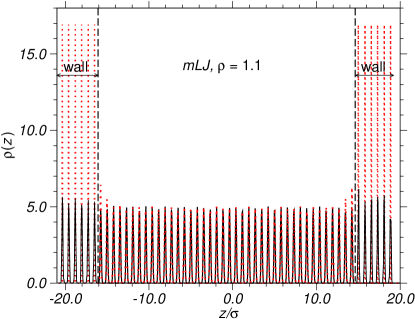
Figure 2 shows the simulation set-up of the system with the crystal in contact with several frozen-in layers of crystalline particles forming walls on both sides. It is clear from Fig. 2 that the structure of the crystal near the wall is identical to that in the bulk. This is also clear from the density profile shown in Fig. 3. There is no change in the density profiles in the layers in contact with the wall and those far away from it. We have also observed that the energy profile of the crystalline layers near the wall is the same as in the bulk indicating that the wall particles do not change the structure and energy of the crystal layers in contact with it. If, instead, the wall is constituted by particles attached to ideal fcc lattice sites, the peaks of the density profiles near the wall are higher than those in layers away from the walls (cf. Fig. 3), indicating that the structure of the crystalline layers in the vicinity of such an ideal wall is different from the bulk.
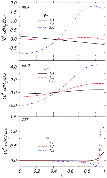
The thermodynamic integrands corresponding to step 2 of the TI scheme and pertaining to the different densities are plotted as a function of in Fig. 4, for the three interaction potentials. The contribution of the Gaussian flat walls in the first step is negligible (less than of ) and hence not reported. A negligible value of indicates that the Gaussian flat walls effectively do not perturb the thermodynamics of the system. The contribution to comes almost entirely from the second step. As Fig. 4 shows, the thermodynamic integrands corresponding to the two relatively long-ranged interaction potentials are similar, while that of the short-ranged hard-sphere potential is qualitatively different. The smoothness of the integrands leads to an accurate determination of the free-energy difference from numerical integration.
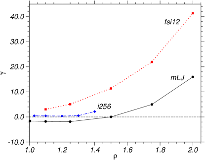
In Fig. 5, we show for the three interaction potentials as a function of the density. For the hard-sphere system, the maximum density we consider is since the packing fraction at this density is , which is very close to the maximum theoretical packing fraction . For the other two soft sphere potentials, we are able to consider larger densities, up to .
Figure 5 shows a non-zero value for as a function of for all the three interaction potentials. The Helmholtz free-energy is given by , where is the energy of the system, the temperature and the entropy. Since the potential energy of the system in contact with the wall is the same as in the bulk and the system is maintained at the same temperature throughout the thermodynamic transformation from the initial to the final states, a non-zero free-energy difference can only be attributed to a change in the entropy of the system. A non-zero free energy difference indicates that the frozen-in layer of crystalline particles imposes an external field on the crystalline particle, perturbing the thermodynamics as compared to the bulk.
For the purely repulsive inverse-twelfth power potential and the hard-sphere potential, the interfacial free energy is always positive from the lowest to the highest densities considered. As can be seen in Fig. 1, for , the inverse twelfth-power potential is more repulsive as compared to the hard sphere interaction, resulting in a larger interfacial free energy. The positive excess free energy corresponding to both the purely repulsive potentials at all densities and the modified LJ potential at high densities originates due to a decrease of the entropy of the particles near the wall as they have less number of ways to arrange themselves near the wall and the thermal oscillations of the particles around their mean positions is also suppressed in the vicinity of the wall.
In case of the modified LJ potential, the interfacial free energy is positive only at high densities. As we go to lower and lower densities, decreases and eventually becomes negative. We have also computed the excess free energy for other interaction potentials and observed that this negative excess free energy occurs only for potentials with attractive interactions. A negative for the mLJ potential at low densities indicates that the wall exerts an effective attractive pinning field on the free particles. Since all the contribution to the change in free-energy comes from the change in entropy , a negative corresponds to , meaning that the entropy of the crystal in contact with a wall which is its frozen version, increases at low densities, if the interaction potential has an attractive component. As shown in a recent work benjamin-horbachpre , this counterintuitive finding is similar to the case of a supercooled binary LJ liquid in contact with an amorphous frozen wall having the same structure as the liquid, where a negative was obtained at low temperatures.
VII Conclusion
In this work, we computed the excess free energy of a crystal in contact with a wall composed of several frozen-in layers of the same crystal, as a function of the density of the crystal. Even though the structure and energy of the crystal in the vicinity of such a wall is the same as in the bulk a non-zero interfacial free energy is obtained, whose origin is purely entropic. A non-zero interfacial free energy indicates that the wall effectively imposes an external field on the bulk system and thereby the thermodynamics of the system is altered.
For purely repulsive interaction potentials, the excess free energy is always positive indicating that entropy of the crystal in contact with the wall is less than that of a bulk crystal. However, for a modified LJ potential, which has an attractive component, the interfacial free energy is negative at low densities, indicating that entropy of the system in contact with the wall is larger than that of the bulk crystal.
Acknowledgements.
The authors acknowledge financial support from the Deutsche Forschungsgemeinschaft (DFG) in the framework of the M-era.Net project “ANPHASES”, grant No. HO 2231/12-1.References
- (1) P. G. de Gennes, Rev. Mod. Phys. 57, 827 (1985); P. G. de Gennes, F. Brochart-Wyart, and D. Quéré, Capillarity and Wetting Phenomena. Drops, Bubbles, Pearls, Waves (Springer, New York, 2004).
- (2) A. C. Zettlemoyer (ed), Nucleation (New York: Dekker, 1969).
- (3) F. F. Abraham, Homogeneous Nucleation Theory (New York: Academic, 1974).
- (4) D. Kashchiev, Nucleation: Basic Theory with Applications (Oxford: Butterworth-Heinemann, 2000).
- (5) A. W. Adamson and A. P. Gast, Physical chemistry of surfaces (Wiley-Interscience, New York, 1997).
- (6) M. Heni and H. Löwen, Phys. Rev. E 60, 7057 (1999).
- (7) R. Benjamin and J. Horbach, J. Chem. Phys. 137, 044707 (2012).
- (8) R. Benjamin and J. Horbach, J. Chem. Phys. 139, 039901 (2013).
- (9) R. Benjamin and J. Horbach, J. Chem. Phys. 139, 084705 (2013).
- (10) A. Fortini and M. Dijkstra, J. Phys.: Condens. Matter 18, L371 (2006).
- (11) B. B. Laird and R. L. Davidchack, J. Phys. Chem. C 111, 15952 (2007).
- (12) V. Krackoviak, Phys. Rep. 476, 51 (2009).
- (13) P. Scheidler, W. Kob, and K. Binder, J. Phys. Chem. B 108, 6673 (2004).
- (14) P. Scheidler, W. Kob and K. Binder, Europhys. Lett. 59, 701 (2002).
- (15) L. Berthier and W. Kob, Phys. Rev. E 85, 011102 (2012).
- (16) A. Cavagna, T. S. Grigera, and P. Verrocchio, Phys. Rev. Lett. 98, 187801 (2007).
- (17) G. Gradenigo et. al., J. Chem. Phys. 138, 12A509 (2013).
- (18) W. Kob, S. Roldán-Vargas, and L. Berthier, Nature Phys. 8, 164 (2011).
- (19) C. Cammarota and G. Biroli, Proc. Nat. Acad. Sci. 109, 8850 (2011).
- (20) K. H. Nagamanasa, S. Gokhale, A. K. Sood and R. Ganapathy, Nature Phys. 11, 403 (2015).
- (21) W. Kob and H. C. Andersen, Phys. Rev. E 51, 4626 (1995).
- (22) R. Benjamin and J. Horbach, Phys. Rev. E 90, 060101(R) (2014).
- (23) M. P. Allen and D. J. Tildesley, Computer Simulations of Liquids (Clarendon, Oxford, 1987).
- (24) D. Frenkel and B. Smit, Understanding Molecular Simulation (Academic, San Diego, 2002); T. P. Straatsma, M. Zacharias, and J. A. MacCammon, Computer Simulations of Biomolecular Systems (Escom, Keiden, 1993).
- (25) R. Benjamin and J. Horbach, J. Chem. Phys. 141, 044715 (2014).
- (26) R. Benjamin and J. Horbach, Phys. Rev. E 91, 032410 (2015).