Spontaneous spin bifurcations and ferromagnetic phase transitions in a spinor exciton-polariton condensate
Abstract
We observe a spontaneous parity breaking bifurcation to a ferromagnetic state in a spatially-trapped exciton-polariton condensate. At a critical bifurcation density under nonresonant excitation, the whole condensate spontaneously magnetizes and randomly adopts one of two elliptically-polarized (up to 95% circularly-polarized) states with opposite handedness of polarization. The magnetized condensate remains stable for many seconds at , but at higher temperatures it can flip from one magnetic orientation to another. We optically address these states and demonstrate the inversion of the magnetic state by resonantly injecting 100-fold weaker pulses of opposite spin. Theoretically, these phenomena can be well described as spontaneous symmetry breaking of the spin degree of freedom induced by different loss rates of the linear polarizations.
Condensation of exciton-polaritons (polaritons) spontaneously breaks the global phase symmetry Deng et al. (2002); Kasprzak et al. (2006); Balili et al. (2007); Baumberg et al. (2008); Ohadi et al. (2012). Owing to their easy optical interrogation, high-speed (ps) interactions, and macroscopic coherence (over hundreds of microns) Nelsen et al. (2013), polariton condensates are excellent candidates to probe and exploit for sensing Sturm et al. (2014); Dreismann et al. (2014), spinoptronics Amo et al. (2010); Ballarini et al. (2013); Cerna et al. (2013), new optoelectronic devices Nguyen et al. (2013); Bhattacharya et al. (2013); Schneider et al. (2013), and quantum simulators Buluta and Nori (2009). The driven-dissipative multicomponent polariton system can undergo additional bifurcations and condense into states which are not eigenstates of the single-particle Hamiltonian, but many-body states with reduced symmetry Aleiner et al. (2012); Zhang et al. (2015). Thus, we should expect that two-component exciton-polariton condensates can also show spontaneous symmetry breaking bifurcations in their polarization state. Spin studies of microcavity polaritons have been of great interest in recent years Lagoudakis et al. (2002); Martín et al. (2002); Kavokin et al. (2003, 2004); Renucci et al. (2005); Krizhanovskii et al. (2006); Gippius et al. (2007); Leyder et al. (2007); Paraïso et al. (2010); Gao et al. (2012); Kammann et al. (2012); Takemura et al. (2014a). However, spontaneous symmetry-breaking bifurcation of spin has not been observed before.
Here, we demonstrate spontaneous magnetization in an exciton-polariton condensate, as a direct result of bifurcations in the spin degree of freedom. Utilizing an optically trapped geometry, condensates spontaneously emerge in either of two discrete spin-polarized states that are stable for many seconds, longer than their formation time. These states emit highly circularly-polarized coherent light (up to 95%) and have opposite circular polarizations. The condensate stochastically condenses in a left- or right-circularly polarized state, with an occurrence likelihood that can be controlled by the ellipticity of the nonresonant pump. The two spin-polarized states can be initialized and switched from one state to another with weak resonant optical pulses. Our system has potential applications in sensing, optical spin memories and spin switches, and it can be implemented for studying long-range spin interactions in polariton condensate lattices.
This article is structured as follows: in Section I we review trapped polariton condensates and the current understanding of polarization in untrapped polariton condensates. In Section II we present the key theme of this work, which is the spontaneous buildup of stochastic circular polarization. In Section III we propose a theoretical framework for the phenomena discussed in this work. We show that stochastic circular polarization is a signature of spontaneous parity breaking. In Section IV we time-resolve the coherent driving of the spin, with resonant excitation. We furthermore investigate the stability of the spin-polarized states against thermal noise and conclude in Section V.
I Introduction
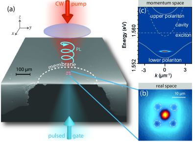
Exciton-polaritons are spinor particles formed by the strong coupling of excitons in a semiconductor quantum well with photons in the microcavity in which they are embedded Kavokin et al. (2007). We create optically-trapped polariton condensates by nonresonant excitation of a semiconductor microcavity membrane [see FIG. 1(a) and Appendix A]. The excitation beam is shaped into a 4-spot pattern [shown by dashed circles in FIG. 1(b)]. The short-wavelength continuous wave (CW) linearly-polarized pump injects an electron-hole plasma at each pump spot, which rapidly relaxes to form excitons, in the process losing all phase information. These reservoir excitons then scatter into polariton states via multiple phonon-polariton and stimulated polariton-polariton collisions Savvidis et al. (2000), and they feed the zero-momentum ground state at the center of the trap. Because of their large effective mass, excitons typically diffuse only very small distances and stay within of the pump spots. Microcavity polaritons, however, are imes lighter giving longer diffusion lengths. Driven by their repulsive excitonic interactions, polaritons can thus travel large distances away from the pump spots within their lifetime Wertz et al. (2010). Once the density inside the trap exceeds the condensation threshold, a macroscopically coherent condensate is formed [FIG. 1(c)]. Because the condensate overlaps only weakly with the pump spots, it shows a narrower linewidth and less decoherence than unconfined condensates Askitopoulos et al. (2013). The optical trapping method used here is similar to optical lattices in cold atomic systems Bloch (2005), but with the major difference that the optical potential also provides gain Wertz et al. (2010); Wouters and Carusotto (2007); Tosi et al. (2012).
Polaritons in quantum-well microcavities have two (spin-up or spin-down) projections of their total angular momentum along the growth axis of the structure, which correspond to right- and left-circularly polarized photons emitted by the cavity, respectively. When the excitation is linearly-polarized an equal population of spin-up and spin-down excitons forms in the reservoir. An initially spin-balanced reservoir, in the absence of pinning to any crystallographic axis, is expected to give a condensate with a stochastic linear polarization Shelykh et al. (2006). In most experiments with polariton lasers the condensates have been found to be linearly polarized along one of the crystallographic axes Deng et al. (2002); Kasprzak et al. (2006). Nevertheless, in some cases a circularly polarized polariton lasing has also been observed Martín et al. (2002); Shelykh et al. (2004); Krizhanovskii et al. (2006); Roumpos et al. (2009); Ohadi et al. (2012). Formation of a circularly polarized condensate is usually associated with the effects of TE-TM splitting, or bosonic amplification of the seed polarization of condensates. In all these cases, a circularly polarized condensate is observed when the symmetry between the spin-up and spin-down polaritons has been explicitly broken in some fashion, by either the pumping geometry (seeding with a circularly polarized pump) or by the imposed rotation of the Stokes parameters due to polarization splitting. As a result, the observed circular polarization was never stochastic (i.e. it is fixed each time the condensate is excited, but it is different on each realization).
II Spontaneous buildup of circular polarization
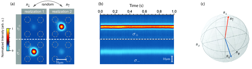
Our experiments reveal a completely different behavior to the previous reports on the polarization of polariton condensates. We observe a strong degree of circular polarization [FIG. 2(a)] when the excitation is linearly polarized (to better than 1 in ), which is stable for many seconds [FIG. 2(b)]. The condensate stochastically adopts either of two opposite circular-polarization states in each realization of the experiment. We call these two states the spin-up () and spin-down () states. By mapping the polarization of the photoluminescence (PL) we measure the polarization vector , where is the measured intensity for horizontal (), vertical (), diagonal (), anti-diagonal (), right-circular () and left-circular () polarizations. We measure all components of the polarization vector (pseudospin) simultaneously and plot the mean of the spin-up and spin down states on the Poincaré sphere separately for 1000 realizations [FIG. 2(c)]. In each realization the wavefunction of the condensate spontaneously collapses into one of the two discrete spin-polarized states which have opposing circular and diagonal components, marked by blue and orange vectors in FIG. 2(c). The linear axis along which the pseudospin flips (marked here as diagonal) does not depend on the geometry of the trap, and it changes direction with the position of the condensate on the sample.
To demonstrate that the buildup of circular polarization is truly spontaneous, we illuminate the sample with a long-duration pulse of using an acousto-optic modulator (AOM). A condensate builds up and picks a random state (e.g. ) and stays in that particular state as long as the pump pulse lasts [FIG. 3(a)]. We then repeat the same measurement but this time we modulate the pump intensity so that a condensate is created and destroyed every . FIG. 3(b) shows how the condensate, although being stable for many seconds, picks a random polarization at every successive realization due to random initial conditions at the onset of condensation. In this case the parity symmetry is broken spontaneously. The buildup of circular polarization is independent of the precise position on the sample, of the sample orientation, of the pump spot orientation, and of the polariton detuning.
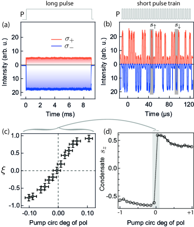
We can also explicitly break the symmetry in our experiments by changing the ellipticity of the pump laser and measure the contrast of the occurrence frequency of spin-up () to spin-down () condensate realizations, . The probability of a realization resulting in state is equal to respectively. FIG. 3(c) shows as a function of the pump circular polarization () averaged over 1000 realizations for each point. As the ellipticity of the pump is increased from linear () to right circular () the probability of creating a condensate in the spin-up state increases; conversely, for the left-circularly polarized pump (), the probability of creating a spin-down condensate increases. With a linearly-polarized pump we have an equal probability of creating a spin-up or spin-down condensate. Although the pump laser is nonresonant with the final polariton states, the initially created carrier spin is not entirely randomized during their multiple carrier-carrier and exciton-phonon scatterings Roumpos et al. (2009); Ohadi et al. (2012); Kammann et al. (2012); Li et al. . As a result of this incomplete spin relaxation of the excited carriers, changing the ellipticity of the pump breaks the symmetry of the condensate toward the same circular polarization as that of the pump. For pump circular polarizations far greater than 0.1 the condensate is formed deterministically in the same polarization state as that of the pump [FIG. 3(d)].
An interesting question here is why we observe the spontaneous buildup of circular polarisation, as opposed to the linear polarisation that is widely reported in the literature Deng et al. (2002); Kasprzak et al. (2006). The key difference between the experiments presented in this work and other studies of polariton condensation lies in the excitation geometry. For our trapped condensates, the pump and condensate are spatially separated, which critically reduces the contaminating interactions between the condensate and reservoir. The large interaction between untrapped condensates and the unpolarized exciton reservoir results in spin-flip scattering of polaritons with reservoir excitons. If there is a depolarized reservoir on top of the condensate, the spin-flip scattering processes minimize any imbalance between circular components of the condensate. This minimization leads to quenching of the buildup of circular polarization, forcing the polaritons to condense only with linear polarization. Moreover it has been shown previously that, because of a smaller overlap with the reservoir, trapped condensates have a smaller linewidth than untrapped condensates Askitopoulos et al. (2013). Our careful studies with temperature and our theoretical calculations (see Section IV.4), show how spin noise in the system results in spin flipping of the condensate. The spin flip rate scales exponentially with noise. Larger linewidth untrapped condensates have higher spin flip rates, which wash out circular polarization effects observed here.
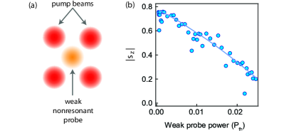
To show the crucial role of the reservoir excitons we place a weak nonresonant linearly-polarized probe beam on top of the condensate as shown in FIG. 4(a). The probe beam which has just a small fraction of the 4-spot pump power (), induces a reservoir of excitons that overlap with the condensate but it does not stop the condensation or reduce the condensate density below the critical circular polarization density. We then measure the absolute average circular polarization degree in each realization, as a function of the weak probe power. As shown in FIG. 4(b), the circular polarization degree decreases monotonously as the probe power increases, demonstrating the quenching of circular polarization due to the influence of the overlapping reservoir. This measurement evidences the importance of the separation of the pump-induced reservoir and the trapped condensate in the observation of ferromagnetic condensates.
Four scenarios might explain the buildup of the stochastic circular polarization depending on populations of same- and opposite- (or cross-) spin polaritons: (i) a higher interaction energy for cross-spin than for same-spin polaritons in a condensate which is in thermal equilibrium, (ii) a higher gain from the cross-spin reservoir, (iii) density-dependent losses enhanced by cross-spin condensed polaritons, and (iv) linear polarization energy splitting accompanied by a dissipation rate splitting which destabilizes the linearly-polarized condensate (‘spin bifurcation’) . As we will show now, our experimental data strongly suggest that scenario (iv) is the correct explanation. In the first scenario (‘energy-minimization’), the condensate free energy is minimized when it acquires circular polarization. This situation could happen in a condensate in thermal equilibrium if the interaction energy of cross-spin polaritons is stronger than that of same-spin polaritons, meaning the coexistence of cross-polarized polaritons is not favored Rubo et al. (2006). However, the interaction with opposite spin polaritons is well known to be weaker than, and opposite to, that of same-spin polaritons Vladimirova et al. (2010); Takemura et al. (2014a, b). Moreover, being externally driven and having short lifetimes, polariton condensates are generally far from thermal equilibrium Kasprzak et al. (2008). We note that “energetical” mechanisms cannot explain why states with elliptical polarization (i.e. not fully circular) are formed. In the second scenario (‘cross-gain’), in order to acquire a circular degree of polarization, the condensate must experience larger gain from the cross-spin reservoir than from the same-spin reservoir. However, the scattering rate from the cross-spin reservoir into the condensate is measured to be significantly smaller than the same-spin Lagoudakis et al. (2002). The third scenario (‘cross-loss’) requires the condensate loss rate to increase when opposite spins are present. If polaritons are directly excited by light, observations have suggested biexciton formation can produce such enhanced losses Paraïso et al. (2010). However, this is only significant when the relative spectral detuning of cavity and exciton is small (), which is far from the case here. We observe the spontaneous buildup of circular polarization throughout the entire to detuning range. In the remaining scenario (‘spin bifurcation’), which we present in Section III for the first time, the buildup of circular polarization is caused by small differences of the energy and dissipation rates of two orthogonal linearly-polarized polariton modes, which is present even at .
Strain-induced splitting of the linear components of polariton condensates has been demonstrated previously Balili et al. (2010); Kłopotowski et al. (2006). In our sample this splitting varies depending on the position on the sample. We observe a linear polarization energy splitting of up to depending on the position of excitation on the membranes. Note that, all the effects reported here are also seen on unetched samples, so strain from patterning is not crucial. However, we observe a higher splitting at the edges of the membrane than in the middle, as there is more stress in the structure at the edges. Due to the curvature of the cavity stopband, any energy splitting is accompanied by a difference of the linewidth (dissipation rate), as explained in Appendix B. This energy splitting between the two linear components combined with a difference in dissipation rates causes the polarization of the condensate to change from linear polarization to circular at a critical density (see Section III).
We emphasize that the stochastic circular polarization here cannot be explained in the framework of the optical spin Hall effect Kavokin et al. (2005); Kammann et al. (2012). In our trapping geometry the condensate is formed at the ground state with () [FIG. 1(c)], where the transverse-electric and transverse-magnetic (TE-TM) splitting vanishes Shelykh et al. (2004). The trap diameter here is 6 times smaller than the observed spin-ring patterns measured for a nonequilibrium condensate formed at much higher in-plane wave-vectors in the same sample Kammann et al. (2012). Moreover, the geometry or the orientation of the trap does not affect the polarization state of the condensate. We also see the stochastic circular polarization with a ring-shaped trap and also in high-order spatial mode condensates Cristofolini et al. (2013); Askitopoulos et al. (2014). Finally, it should be noted that any theoretical picture that assumes the buildup of circular polarization arises only because of the geometrical arrangement of the pump, would necessarily fail to explain the most essential part of this work, which is the spontaneous symmetry breaking (stochastic behavior).
III Spin Bifurcation Theory (Broken Parity)
Our theory is a development of the theory of polariton weak lasing in two coupled condensation centers Aleiner et al. (2012) now for the case of the spin degree of freedom. Here, we have right and left circular polarizations instead of two separated condensates, and we also allow for the gain-saturation nonlinearity in the system.
The order parameter for an exciton-polariton condensate is a two-component complex vector , where and are the spin-up and spin-down wave functions. The components of the order parameter define the measurable condensate pseudospin , and the normalized spin vector , where are the Pauli matrices. The components of this vector contain information about the intensities and relative phases of the emitted light. The order parameter evolves according to the driven dissipative equation
| (1) | ||||
or in components:
| (2a) | ||||
| (2b) | ||||
Here, is the pumping-dissipation balance, is the (average) dissipation rate, is the incoherent in-scattering (or ‘harvest’ rate), and captures the gain-saturation term with Keeling and Berloff (2008). Here, this gain saturation depends on the total occupation of the condensate (treated more generally in Appendix C). It is assumed now that (horizontal) and (vertical) linearly-polarized single-polariton states have different energies and dissipation rates. The energy of the -polarized state is shifted by , and the energy of the -polarized state by . The dissipation rate from the -polarized state is , while the dissipation rate from the -polarized state is (see also Appendix B). Finally, is the repulsive interaction constant for polaritons with the same spin, and is the interaction constant for polaritons with opposite spins.
From Eq. 1 we obtain for the components of the pseudospin vector ():
| (3a) | ||||
| (3b) | ||||
| (3c) | ||||
and the related equation for the total spin . There are two sets of solutions, which we call here the paramagnetic and ferromagnetic solutions.
Paramagnetic solutions.
These give simple condensation into either or linearly-polarized states. The state possesses the longest lifetime, and the condensation threshold is reached for this state first at . There is no parity breaking for this condensate: , with , so that the occupations of and components are equal. However, this condensate solution becomes unstable for . The values of the critical occupation and the critical pumping rate are
| (4) |
Note that this instability is present also for equal dissipation rates, i.e. when . In this case, the system (Eq. 3a-c) describes the self-induced Larmor precession of the pseudospin vector. Incorporating energy relaxation (e.g., using small negative ) then leads to the formation of the -polarized condensate—an intuitively expected result.
Ferromagnetic solutions.
The key ingredient of our theory is the presence of the parameter describing the variation of dissipation rates. This parameter allows the formation of the ‘weak lasing’ regime Aleiner et al. (2012), which is characterized by two important features: (i) the -polarized condensate is also unstable, and (ii) when the -polarized condensate loses stability at the critical occupation , it continuously transforms into one of the two ferromagnetic states. While Eqs. (2) are parity symmetric, i.e., they are not affected by the interchange of left and right circular polarization, the new solutions are characterized by broken parity symmetry and by spontaneous formation of either left or right elliptical polarization. These solutions are
| (5a) | |||
| (5b) |
where the positive root of the second equation in Eq. (5b) should be taken. We note that while the sign of is always negative, and have opposite signs for the two solutions. This means that the left-circular component is accompanied by a diagonal component, and the right-circular by anti-diagonal. Moreover, if these components change for some reason, they mirror each other as long as the total condensate occupation stays fixed. We label these two solutions as the and spin states.
The spin-independent model for the gain saturation used in this Section is sufficient to describe the experimentally observed features. However, the spin relaxation in the reservoir can be slow Li et al. , and in this case the model should be modified to allow the saturation terms to depend on the individual occupations of the left- and the right-circular polarization components rather than the total occupation only. The parity breaking is still present after this modification; however, the stability of solutions becomes more complex. The ferromagnetic solutions can now become unstable and transform into periodic cycles Rayanov et al. (2015), the dynamics of the pseudospin can become irregular, and this can also result in the formation of the stable -polarized condensate at high pumping powers. See Appendix C for more details.
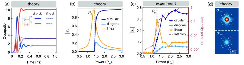
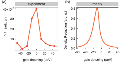
Numerical calculations for the occupation of the two circular components of the wavefunction when (dotted lines) and when are shown in FIG. 5(a). Here, the condensate is initialized with a small asymmetry in spin-up and spin down occupations (<1%). Below the critical occupation , the condensate is linearly polarized, but when the occupation is increased above the threshold , the condensate adopts one of two elliptically polarized configurations depending on the initial conditions. In the experiment, the stochastic behavior is due to random spin fluctuations at the onset of the condensation. In theory, we can reproduce it by randomly setting the initial conditions. Numerical calculations of the condensate polarization versus excitation power are shown in FIG. 5(b). Directly at the condensation threshold the condensate is linearly polarized, but once it reaches the critical occupation (, marked by a dashed grey line), the linear component is quenched and circular polarization builds up. This behavior reproduces the experimental data, as shown in FIG. 5(c). We observe an initial buildup and subsequent quenching of linear polarization with the continuing increase of circular polarization at (marked by a dashed grey line, with total intensity marked by a dotted red line). Once circular polarization is achieved, the orientation of the condensate circular polarization becomes stochastic under linearly polarized pumping.
We can extend Eq. (1) and account for 2D real-space degrees of freedom by using complex Ginzburg-Landau-type equations Wouters and Carusotto (2007); Keeling and Berloff (2008); Dreismann et al. (2014), which in addition to the pump and decay also incorporate a repulsive potential due to the excitons in the pump spots and an energy relaxation Wouters et al. (2010) for polaritons in the trap:
| (6) |
where is the effective mass of the polaritons. The harvest rate is given by , where is the spin-independent spatial profile of the excitation, is the decay rate of the exciton reservoir, and is the incoming rate of polaritons into the condensate. The gain saturation is given by . The repulsive potential due to the interaction of polaritons with the exciton reservoir is given by , where , and are the interaction constants of polaritons with the exciton reservoir and the pump spot respectively, and is the density of the exciton reservoir. Here, is a phenomenological constant that gives the energy relaxation. The density profile of the two circular components of the wave function in the steady state [FIG. 5(d)], for the case of a trapped condensate in the middle of the 4 pump spots, exhibits a circular polarization degree of . Note that with and only polarization splitting (including TE-TM splitting), our 2D simulations do not show bistable condensation.
It is important to note the differences between the ferromagnetic states we discuss here and the magnetization transition in equilibrium cold atom systems Sadler et al. (2006); Stamper-Kurn and Ueda (2013). First, the parity breaking bifurcation described above does not reduce the energy of the system (unlike for atoms). In fact the energy of elliptically polarized states is higher than that of linearly polarized states. Second, the in-plane components of the spin do not vanish completely. Third, we have a magnetized condensate with only two possible orientations, whereas in atomic systems ferromagnetic domains with continuous variable orientation are observed.
If the Hamiltonian and the initial state of a system are symmetric under the exchange of spin-up and spin-down components, but the final state is not, the parity symmetry is spontaneously broken. This is indeed the case here: We excite an equal population of spin-up and spin-down polaritons, which spontaneously condense, but form highly circularly polarized macroscopic states in the absence of any external magnetic field.
IV Resonant excitation
The GaAs substrate commonly used in the fabrication of GaAs microcavities is opaque at the emission wavelength () of the cavity polaritons. As a result, the back side of the cavity is resonantly inaccessible. Resonant excitation of the cavity from the front side has complications with backscatter from the laser, especially in high finesse cavities and at normal incidence, where the condensate emission mode is located. To circumvent this problem we chemically etch the substrate to form membranes of thickness and diameter [see FIG. 1(a)]. For resonant excitation, we use a narrow-linewidth () CW laser, which is amplitude modulated with a second AOM. We call this resonant laser the ‘gate’. We use two photomultipliers and a fast oscilloscope to time resolve the left- () and right-circular () polarization intensity of the condensate emission. The resonant excitation laser, the nonresonant pump laser, the cameras and the oscilloscope are all synchronized, which allows us to vary the delay time and amplitudes of each laser pulse on demand.
IV.1 Resonant initialization of spin states
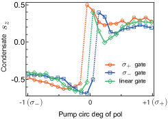
We can control the polarization of the trapped condensate with the gate laser. In this case, we additionally resonantly excite the condensate (which is generated by the four nonresonant pump spots) with a second laser from the backside of the microcavity membrane. This gate can be linearly, left-, or right-circularly polarized. FIG. 6 shows the condensate circular degree of polarization versus that of the pump. In the green curve which shows the behavior when the gate is linearly polarized, we reproduce the same result as that in FIG 3(d). However, when a right (or left) circularly polarized gate is applied, the curve shifts to the left (or right). In other words, with a linearly polarized pump, the condensate initializes in a right (or left) circularly polarized state. The imbalance caused by the resonant gate cancels out with an opposite circularly polarized pump with a circular polarization degree of .
IV.2 Elliptically-polarized pump: coherent driving

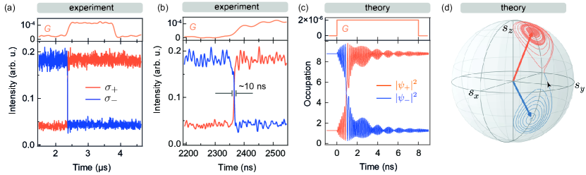
In a first experiment, we initialize a condensate in the spin-down state () by making the pump laser slightly left-circularly polarized (‘asymmetric pumping’). Once the condensate is created, we excite the sample resonantly from the back side with an oppositely circularly polarized () gate. FIG. 7(a) shows the intensity of and components of the condensate emission during this gating. We see a reduction in intensity for the component which is opposite to the gate laser polarization and an increase for the same spin polarization component. To account for this in the theory, we add a new term to Eq. 2, corresponding to the resonant laser:
| (7a) | ||||
| (7b) | ||||
where uses the Heaviside step function to give a square pulse with amplitude which starts at time and lasts for , and is the excitation frequency. To account for the elliptically-polarized pumping we modify to . Numerical calculations [FIG. 7(b)] show the case , , where is the occupation of the condensate, and . The dotted line marks the time average of the oscillations. The condensate pseudospin vector precesses around the stationary state pseudospin vector at a frequency of in a limit cycle [see FIG. 7(c)]. In the case where the condensate is highly spin-polarized and the gate is at resonance (), the oscillation frequency is equal to the self-induced Larmor precession frequency (Appendix F). This sets the fastest possible spin dynamics in the system, and does not depend on the gate intensity. Here, the condensate pseudospin oscillates faster than our detection time resolution and consequently we only see the average effect in FIG. 7(a). The coherent driving reported here strongly depends on the detuning of the gate laser frequency relative to that of the condensate. The resonance width at which we can drive the condensate is determined to be 10-, as explained in Appendix E.
In the case of FIG. 7(d) the intensity of the gate laser is increased by five times with respect to that in (a). Under these conditions, the time average of the circular component of the condensate emission becomes almost unpolarized. If the amplitude of the resonant excitation is large enough, the condensate pseudospin can cross over to the second attractor (the spin-up state) and form a large trajectory which encompasses both spin-up and spin down stationary states with a characteristic period doubling Alexeeva et al. (2014) [FIG. 7(e,f)]. The dotted lines in (e) mark the time average of the oscillations. FIG. 7(g) shows the power dependence of the average circular polarization as a function of the intensity of the gate. As the oppositely polarized gate intensity is increased, we see the condensate average circular polarization converges to zero. Here, we have the gate resonant with the condensate. However, the coherent driving strongly depends on the detuning of the gate laser frequency to that of the condensate. The resonance width where we can drive the condensate is determined to be 10-, as explained in Appendix E. That theory and experiment agree regarding the observed average polarization over the whole range of gate powers, and also the observation of a resonance (see Appendix E) strongly suggests that our description in terms of coherent driving is valid.
In summary, the fixed points of broken parity symmetry () become unstable due to small perturbations and convert to limiting circles around stationary states. The precession is linear for small gate amplitudes but it becomes nonlinear for large amplitudes. This is manifested by oscillation of the condensate parameters, occupation and polarisation with time. In this linear regime, the gate pulse appears to act as if it induces an effective magnetic field, around which the condensate polarisation precesses. It is worth noting that this system can exhibit chaotic behavior with increased amplitude of the pulse. Increasing the amplitude first results in period doubling, and eventually leads to chaos (Feigenbaum scenario) Alexeeva et al. (2014). The ability to coherently control the spin of the condensate suggests its utility for computational operations.
IV.3 Linearly-polarized pump: spin switching
We now explain the case when the nonresonant pump is linearly polarized. In this case there is no external ‘force’ to drive the condensate to a specific spin state. As a result, once the circular component of the condensate pseudospin crosses zero, it falls into the opposite spin state’s attractor. FIG. 8(a) shows a realization which lasts for with the condensate first initialized in the spin down state (). We resonantly excite the condensate with an oppositely polarized gate (). This causes the switching of the polarization of the condensate to the same polarization as that of the gate. The gate, which is in duration, is then turned off but the condensate remains in the switched polarization because the pump is linearly polarized and the symmetry is not explicitly broken. This shows that we are capable of manipulating the polarization of the condensate on demand, while also reinforcing our observation that the condensate picks a polarization spontaneously when it is formed. It should be noted that the state of the condensate does not change when the circular polarization of the gate is the same as that of the condensate.
If the symmetry breaking was somehow set by the parameters of the experiment, as in the previous example where the pump was slightly elliptical, the condensate would switch back to its original state after the gate beam was turned off. Instead, a very small gate field in the cavity can initiate coherent switching. The upper panel in FIG. 8(a) shows the transmitted gate intensity when the pump is blocked. Indeed, the gate power before the cavity is , which is 50 times weaker than the pump power. However, only a small fraction of this resonant beam couples to the cavity in our setup. Therefore, a suitable comparison of the intensity of the gate to that of the condensate is to compare the transmitted intensity of the gate to the intensity of the condensate in the same direction. We find that the gate intensity is more than 60 times weaker than the condensate intensity, when the gate laser frequency is tuned to the bottom of the polariton dispersion (accounting for the blueshift of the condensate).
By estimating the occupation number of the condensate (see Appendix D) we find that only 13 polaritons are enough to reverse the spin state of the condensate. The condensate switching time is less than (our detection limit), and is 10 times faster than the switching time of the AOM [FIG. 8(b)]. This important fact shows that the condensate does not follow the optical gate adiabatically. Simulations of the spin-switching with minimum resonant gate intensity are shown in FIG. 8(c). The polarization of the gate is opposite to that of the condensate and we have assumed symmetric pumping rates for the spin-up and spin down condensates i.e. . The condensate polarization reverses within once the gate is applied and remains in that state after the pulse is turned off during continued spin evolution [FIG. 8(d)]. Switching requires a minimum gate intensity, to twist the condensate pseudospin onto the equator in the Poincaré sphere. This sets a threshold for the gate power. By measuring the gate flux, and using the switching time of , an upper bound of the minimum energy for switching the state of the condensate is found to be , comparable to state-of-the-art optoelectronic switches with similar speeds Nozaki et al. (2010). We emphasise, however, that the theoretical limit for the minimum switching energy is 50 times smaller because the spin dynamics of the system () is 50 times faster than our detection limit. This polaritonic system is then an extremely low-power switch.
Multistability has indeed been demonstrated before in resonantly pumped condensates Paraïso et al. (2010); Cerna et al. (2013). However, there are several major differences between our system and that of the Deveaud group. In Deveaud’s experiments the physical process causing multistability is the nonlinear nonradiative losses in the polariton gas due to the formation of biexcitons. These losses are only significant when the polariton gas energy is close to the biexciton energy () Wouters et al. (2013). In contrast here, the bistability that we observe is present below the biexciton energy. There is no phase transition in Paraïso et al. work Paraïso et al. (2010) on multistability and symmetry is not spontaneously broken. In contrast, we observe spin symmetry breaking while the power thresholds of the left- and right-circularly polarized states are the same, allowing us to observe spontaneous magnetization. In the Deveaud multistable system, in order to switch the polarization one has to inject an opposite-spin polariton density equal to the density difference of spin-up and spin-down polaritons. In contrast, in our experiments, the condensate switches with a gate intensity 60 times weaker than the condensate. Theoretically, the gate intensity can be much weaker and the reason that we do not see switching at even weaker powers experimentally is due to spin fluctuations in the condensate, as discussed below. Finally, we note that other microstructured systems such as microdisk lasers can also show bistability. The whispering gallery modes in microdisk lasers can have clockwise or counterclockwise propagating lasing modes Hill et al. (2004). When the coupling between the two modes is small, a cross-gain saturation causes one of the modes to dominate. The system can therefore operate in “flip-flop” mode and the two modes can be excited and switched with weak optical pulses Liu et al. (2010).
IV.4 Thermal noise: spin flipping
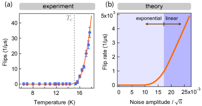
Above the spin bifurcation occupation threshold (), any small perturbation induces a ‘restoring force’, which drives the condensate toward the attractor once the perturbation is stopped. This restoring force keeps the condensate around the attractor for small spin fluctuations. However, for sufficiently large perturbations, the condensate can flip to the other attractor with the opposite circular polarization. In the experiment, for sample temperatures near the observed spin-polarized states remain stable for many seconds (longer than the stability of our experiment can be maintained). However, increasing the temperature above induces spin flips in the condensate during a measurement time window of . The measured rate of the spin flipping beyond is a nonlinear function of the sample temperature as shown in FIG. 9(a). It is important to note that we do not have a real threshold for the occurrence of spin flipping here. In fact, the spin-flip rate increases exponentially with temperature right from , until it becomes significant in the finite-time measurement window. We can account for this phenomenon by adding a thermally induced noise to our theory. This thermal noise , which is similar to the Johnson noise, is included in Eq. (2) to give Langevin-type equations:
| (8a) | ||||
| (8b) | ||||
where with is a realization of Gaussian random processes with zero mean and -like two-point correlation function
| (9) |
At finite temperature the intensity of the noise can be written approximately as , with the -contribution being a shot noise from the reservoir Aleiner et al. (2012) and the thermal part defined by spin-flip polariton-phonon scattering.
The flip rate vs noise amplitude using stochastic simulations [FIG. 9(b)] reveals an Arrhenius-like increase at a critical threshold followed by a crossover to a linear regime. This model gives an excellent account of the dynamics [FIG 9(a)]. For temperatures beyond we reach the time resolution of our detection. As a result, we cannot completely span the crossover to the linear spin-flip regime in our experiment. A fit of the simulation results to the experimental data in FIG. 9(a) gives , which sets the dependence of spin flip rate on . We can then explore how this noise perturbs the spin system given by equations (8).
Inclusion of noise produces a spin flip rate that can overcome the effective spin potential barrier (see Appendix F). For the case in which the circular degree of polarization is high, the spin-flip process can be considered as a one-dimensional Kramers transition. The spin-flip rate can then be estimated as
| (10) |
We note that for and the condensate occupation , the zero-temperature shot-noise spin-flip rate (set by ) is negligible for our observation timescales (). The critical temperature given by depends dramatically on the measurement window time . While the phonon-polariton interaction in our system gives , at lower temperatures the condensate spin lifetime rapidly exceeds the stability time of our experimental apparatus (many seconds). Modifying the phonon-polariton interaction thus has an enormous effect on the spin stability. Finally, we note that in a similar fashion to thermal noise, an overlapping reservoir can also induce spin noise in the condensate. The spin noise causes condensate spin flips, which result in the reduction of the time-averaged circular polarization. Theoretically, this can be studied by introducing a noise term similar to Eq. 9, but instead of depending on temperature the noise intensity depends on the overlapping reservoir density Read et al. (2009).
V Concluding remarks
In summary, we showed how spin can emerge spontaneously in nonresonantly-pumped polariton condensates. We found that for trapped condensates, in the case where the pump is linearly polarized, parity symmetry is spontaneously broken by spin fluctuations at the onset of condensation. Fluctuations are amplified by nonlinearities in the condensate formation due to the energy and lifetime splitting of the linear polarization components, producing a spin-up or spin-down condensate. The symmetry can be explicitly broken by applying a slightly elliptically polarized pump, which increases the likelihood of forming condensates with the same spin as the pump. In the case where the pump is linearly polarized, we switched the condensate state using a 60-fold weaker resonant gate pulse with an opposite circular polarization. This situation changes when the pump is elliptically polarized, where instead of switching, the condensate pseudospin precesses around stationary states in limit cycles. Finally, we showed how thermal excitations can induce spin flips with a rate that increases exponentially with sample temperature.
We demonstrated here one way to explicitly break symmetry utilizing elliptical polarization pumping geometries. One could also break the symmetry by introducing a magnetic field to split the energy of the spin-down and spin-up condensates. Alternatively, the pumping symmetry could be broken with spin current injection. These experiments thus exhibit rich physics with potential applications in sensing.
The observation of spontaneous discretized spin-polarized states also has interesting consequences in the physics of condensate lattices. The possibility of shared reservoirs, and a Josephson type tunneling Lagoudakis et al. (2010) between adjacent sites, could provide new phenomena previously unobserved in driven bosonic systems. Magnetic phase transitions, geometric frustration and spontaneous pattern formation of spin in lattices, domain formation, topological spin insulators, and topological defects are a few examples of magnetic systems that could be studied, all within a highly-controlled bosonic many-body system.
While the condensed polariton lattice resembles nanomagnet arrays Jamet et al. (2001); Hai et al. (2010), it has the inherent advantages of tunable nonlinearity, longer spin relaxation time, ps response, rapid optical addressing and manipulation, and adaptable scalability. The spin-polarized state at zero magnetic field is retained for many seconds, 10 orders of magnitude longer than the condensation time, making it a suitable candidate for optical spin-based memories.
Spin switching with only a fraction of the condensate density, which is a direct result of the nonlinearity in our system, can be used for low power optical and electrical sensing and spin switches. Finally, the possibility of coherent driving allows the realization of superpositions of spin-up and spin-down states, which are the key requirements for quantum information processing.
Acknowledgments
We acknowledge discussions with B. L. Altshuler and N. G. Berloff. This work was supported by EPSRC Grant No. EP/G060649/1, EP/L027151/1, EU Grant No. CLERMONT4 235114, EU Grant No. INDEX 289968, ERC Grant No. LINASS 320503, the Leverhulme Trust Grant No. VP1-2013-011, Spanish MEC (Grant No. MAT2008-01555), the Greek GSRT ARISTEIA Apollo program and Fundación La Caixa, and Mexican CONACYT Grant No. 251808. F. P. acknowledges financial support from EPSRC at the University of Cambridge and a Schrödinger grant at the University of Oxford. The data corresponding to all the figures in this paper can be found at https://www.repository.cam.ac.uk/handle/1810/248036
.
Appendix A Experimental methods
The cavity’s top (bottom) distributed Bragg reflector (DBR) is made of 32 (35) pairs of Al0.15Ga0.85As/AlAs layers of /. Four sets of three GaAs quantum wells (QW) separated by thick layers of Al0.3Ga0.7As are placed at the maxima of the cavity light field. The 5/2 () cavity is made of Al0.3Ga0.7As. The microcavity sample is chemically etched from the substrate side to form diameter membranes allowing optical access from the back of the sample for resonant excitation [FIG. 1(a)]. The sample shows condensation under nonresonant excitation Tsotsis et al. (2012). The excitation laser is a single-mode CW Ti:Sapphire, which is amplitude modulated using an AOM with a rise time of . To pattern the pump intensity a spatial light modulator was used Cristofolini et al. (2013).
Appendix B Strain-induced linear polarization splitting
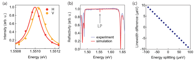
The measured energy of the ground state - and -polarized photoluminescence far below threshold is shown in FIG. 10(a). The energy splitting of the linearly polarized modes varies across the sample surface, reaching its maximum at the edges and minimum at the center of the membranes. This observation suggests that the splitting is correlated to the level of strain across the microcavity structure, since the latter is expected to possess a similar spatial dependence: namely to be strongest at the boundary between etched and non-etched regions and relax towards the central parts of the membranes. Note that we observe all the same phenomena even in unetched samples, as strain is universally present from the III-V heterostructure growth.
Strain-induced splitting of the initially degenerate polariton states at into orthogonal linearly polarized modes has been demonstrated in previous works Balili et al. (2010); Kłopotowski et al. (2006). Both the excitonic and the photonic parts of the polariton can be affected by strain to produce such an anisotropy. In the former case, the initial splitting of the bright exciton states due to exchange interactions are enhanced by strain-induced mixing of the heavy and light hole valence bands, thereby reducing the symmetry of the QW Aleiner and Ivchenko (1992); Ivchenko et al. (1996); Balili et al. (2010). In the latter case, strain induces a small birefringence in the cavity and/or DBRs, hence lifting the degeneracy between the and axes Kłopotowski et al. (2006).
Because of the finite curvature of the cavity stopband, splitting the lower polariton into two orthogonal modes necessarily induces a difference of their linewidths as well. For the microcavity structures studied in this work the polariton modes are located on the low-energy side of the stopband [FIG. 10(b)]. In this case the mode possessing higher energy will exhibit a narrower linewidth, since it is located closer to the stopband center, where the DBR reflectivity is at its maximum. Correspondingly, the lower energy mode will exhibit a larger linewidth, since it is located closer to the edge of the stopband, where the DBR reflectivity starts to drop. For an energy splitting of the order of , transfer matrix calculations predict a linewidth difference of approximately [FIG. 10(c)].
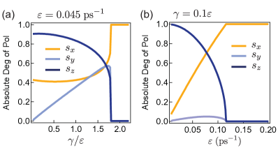
This small difference in linewidth is not resolvable with our instruments. However, it should be noted that any nonzero linewidth difference, as long as it is negative sign relative to the energy splitting, eventually leads to the bifurcation of the circular polarization at a critical threshold [FIG. 11(a)]. Moreover, if the ratio of the linewidth difference to energy splitting is kept constant (as we have according to our transfer matrix simulations), the condensate becomes linearly polarized at high energy splittings [FIG. 11(b)]. This is indeed what we observe at the edges of the membrane, where the energy splitting is as high as .
Appendix C Variable cross spin saturation
For the case when the same-spin and cross-spin gain-saturation nonlinearities are different we have:
| (11a) | ||||
| (11b) | ||||
where and we have now two saturation parameters, and . The saturation is controlled by individual occupations of circular components when , and the saturation is controlled by the total occupation when . In general, . Equations above in the matrix form read
| (12) | ||||
and the equations for pseudospin components are
| (13a) | |||
| (13b) | |||
| (13c) | |||
C.1 Linearly polarized condensates (parity conserved)
These particular solutions are given by , , and . -polarized condensates (upper sign) can exist for . -polarized states (lower sign) appear for . Considering their stability with respect to small fluctuations: , , , and , with , we have linearized equations
| (14a) | |||
| (14b) | |||
| (14c) | |||
Taking we see that fluctuations in always decay, while (14b,c) produce the equation for the Lyapunov exponent ,
| (15) |
The stability of the -polarized condensate is lost when one root of this equation crosses zero. This corresponds to the critical occupation and critical pumping ,
| (16) |
The stability of polarized state depends on the interrelation between and . For this state is always unstable. However, if the stable polarized state can be formed for large enough condensate occupations (far above the threshold).
C.2 Elliptically polarized condensates (parity broken)
These solutions with are given by
| (17a) | |||
| (17b) | |||
| (17c) | |||
Substitution into (13a) gives
| (18) | ||||
The positive root of this equation for should be taken. Also, it is necessary to satisfy the condition , which gives . This means that the weak lasing solutions appear continuously from the -polarized solution at the critical pumping .
The stability of weak lasing states can also be lost. Numerical analysis shows the following typical scenario of evolution of the condensate polarization state with increasing for . First, the linearly polarized state is formed. Then it transforms into a weak lasing, elliptically polarized state. The stability of the latter is also lost with increasing , resulting in some irregular, quasi-chaotic dynamics and/or in the oscillatory motion of the pseudospin vector. Finally, for large the stable polarized state is formed.
Appendix D Estimate for particle number
The condensate particle number is experimentally measured by:
| (19) |
where is the photon flux, is the polariton lifetime, and is the photon Hopfield coefficient. The photon flux is measured by:
| (20) |
where is the photoelectron sensitivity of the CCD, is the total detection efficiency including the camera quantum efficiency and the total optical transmission efficiencies, and is the spatially-integrated count rate of the CCD. Inserting these values in Eq. (19) gives the particle number , at .
Appendix E Resonance width
We study the reduction of the opposite component of the condensate circular polarization to the gate laser [marked by in FIG. 7(d)] as the ‘detuning’ of the gate varies, while the gate power remains constant. In order to change the detuning of the gate laser frequency with respect to the condensate, instead of changing the frequency of the laser, we tune the condensate frequency by changing the pump intensity. The trapped condensate ‘blueshifts’ as the pump intensity is increased, mainly due to the repulsive interaction between the polaritons. This contrasts with the case of untrapped condensates, where interactions of polaritons with the excitons in the reservoir is the source of blueshifts Wouters et al. (2008); Wertz et al. (2010); Askitopoulos et al. (2013). In the 4 spot trapped geometry, we have a blueshift of and as a result we can tune the condensate energy accurately with respect to that of the gate. FIG. 12(a) shows with respect to the detuning of the gate laser. We observe a sharp resonance, with a full width at half maximum (FWHM) of . FIG. 12(b) shows the theoretical curve versus the gate detuning (), which resembles a Lorentzian profile with a linewidth of . Theoretically, the linewidth of the resonance is defined by the noise in Eqs. (8). The FWHM of the Lorentzian resonance peak is . We note that the resonance frequency is slightly redshifted, due to the effect of the linear polarization splitting and the decay rate splitting,
| (21) |
Appendix F The Kramers flip rate
From Eq. (8) we can obtain the spin vector equations:
| (22a) | |||
| (22b) | |||
| (22c) | |||
where the correlators of real-function noise are
| (23) |
Here we consider limiting case when two parity breaking states are formed near the north and south poles of the Poincaré sphere, i.e., . The spin components of fixed states in this limit are , , , where is the root of . In what follows we also denote and by assumption . Being excited away from the fixed state, the spin exhibits fast self-induced Larmor precession and slow relaxation. The precession frequency is , so that near the stationary states.
The spin should be driven by noise into the equatorial plane () in order to flip. This Kramers problem can be simplified if we perform averaging over fast precession of the spin vector. This treatment is valid as long as . Consider the motion in the north hemisphere. We assume that the number of polaritons does not change during the flip, i.e., is fixed to , and we consider the case of large occupations, . Omitting the -terms from Eqs. (22a,b) we find that for a given value of the averages over one cycle of the other two components are and . Then, from (22c) we obtain the equation for slow evolution of
| (24a) | |||
| (24b) |
This expression for the effective potential is not valid for small , where it diverges logarithmically. The top of the barrier should be cut off when becomes comparable to , that is for . The value of potential on the top of the barrier is then . The bottom of the well is positioned at . As a result, the spin should overcome the barrier
| (25) |
Using the known result for the Kramers first passage time in the one-dimensional problem Zwanzig (2001), we obtain the spin-flip rate
| (26) | ||||
This expression assumes and . The pre-exponent cannot be written exactly by this method, since we do not know the shape of the effective potential near the top of the barrier. It can be estimated as .
Appendix G Simulations and numerical parameters
The parameters used for all the simulations are as follows:
0D simulations: ; ;
; ; ;
2D simulations: ; ; ; ; ;
; ;
; .
References
- Deng et al. (2002) Hui Deng, Gregor Weihs, Charles Santori, Jacqueline Bloch, and Yoshihisa Yamamoto, “Condensation of semiconductor microcavity exciton polaritons,” Science 298, 199 –202 (2002).
- Kasprzak et al. (2006) J. Kasprzak, M. Richard, S. Kundermann, A. Baas, P. Jeambrun, J M J Keeling, F M Marchetti, M H Szymańska, R. André, J L Staehli, V. Savona, P B Littlewood, B. Deveaud, and Le Si Dang, “Bose-einstein condensation of exciton polaritons.” Nature 443, 409–14 (2006).
- Balili et al. (2007) R. Balili, V. Hartwell, D. Snoke, L. Pfeiffer, and K. West, “Bose-einstein condensation of microcavity polaritons in a trap,” Science 316, 1007 –1010 (2007).
- Baumberg et al. (2008) J. Baumberg, A. Kavokin, S. Christopoulos, A. Grundy, R. Butté, G. Christmann, D. Solnyshkov, G. Malpuech, G. Baldassarri Höger von Högersthal, E. Feltin, J. F Carlin, and N. Grandjean, “Spontaneous polarization buildup in a room-temperature polariton laser,” Physical Review Letters 101, 136409 (2008).
- Ohadi et al. (2012) H. Ohadi, E. Kammann, T. C. H. Liew, K. G. Lagoudakis, A. V. Kavokin, and P. G. Lagoudakis, “Spontaneous symmetry breaking in a polariton and photon laser,” Physical Review Letters 109, 016404 (2012).
- Nelsen et al. (2013) Bryan Nelsen, Gangqiang Liu, Mark Steger, David W. Snoke, Ryan Balili, Ken West, and Loren Pfeiffer, “Dissipationless flow and sharp threshold of a polariton condensate with long lifetime,” Physical Review X 3, 041015 (2013).
- Sturm et al. (2014) C. Sturm, D. Tanese, H. S. Nguyen, H. Flayac, E. Galopin, A. Lemaître, I. Sagnes, D. Solnyshkov, A. Amo, G. Malpuech, and J. Bloch, “All-optical phase modulation in a cavity-polariton mach–zehnder interferometer,” Nature Communications 5, 3278 (2014).
- Dreismann et al. (2014) Alexander Dreismann, Peter Cristofolini, Ryan Balili, Gabriel Christmann, Florian Pinsker, Natasha G. Berloff, Zacharias Hatzopoulos, Pavlos G. Savvidis, and Jeremy J. Baumberg, “Coupled counterrotating polariton condensates in optically defined annular potentials,” Proceedings of the National Academy of Sciences 111, 8770 (2014).
- Amo et al. (2010) A Amo, LiewT. C. H., AdradosC., HoudreR., GiacobinoE., KavokinA. V., and BramatiA., “Exciton-polariton spin switches,” Nat Photon 4, 361–366 (2010).
- Ballarini et al. (2013) D. Ballarini, M. De Giorgi, E. Cancellieri, R. Houdré, E. Giacobino, R. Cingolani, A. Bramati, G. Gigli, and D. Sanvitto, “All-optical polariton transistor,” Nature Communications 4, 1778 (2013).
- Cerna et al. (2013) R. Cerna, Y. Léger, T. K. Paraïso, M. Wouters, F. Morier-Genoud, M. T. Portella-Oberli, and B. Deveaud, “Ultrafast tristable spin memory of a coherent polariton gas,” Nature Communications 4, 2008 (2013).
- Nguyen et al. (2013) H. S. Nguyen, D. Vishnevsky, C. Sturm, D. Tanese, D. Solnyshkov, E. Galopin, A. Lemaître, I. Sagnes, A. Amo, G. Malpuech, and J. Bloch, “Realization of a double-barrier resonant tunneling diode for cavity polaritons,” Physical Review Letters 110, 236601 (2013).
- Bhattacharya et al. (2013) Pallab Bhattacharya, Bo Xiao, Ayan Das, Sishir Bhowmick, and Junseok Heo, “Solid state electrically injected exciton-polariton laser,” Physical Review Letters 110, 206403 (2013).
- Schneider et al. (2013) Christian Schneider, Arash Rahimi-Iman, Na Young Kim, Julian Fischer, Ivan G. Savenko, Matthias Amthor, Matthias Lermer, Adriana Wolf, Lukas Worschech, Vladimir D. Kulakovskii, Ivan A. Shelykh, Martin Kamp, Stephan Reitzenstein, Alfred Forchel, Yoshihisa Yamamoto, and Sven Höfling, “An electrically pumped polariton laser,” Nature 497, 348–352 (2013).
- Buluta and Nori (2009) Iulia Buluta and Franco Nori, “Quantum Simulators,” Science 326, 108–111 (2009).
- Aleiner et al. (2012) I. L. Aleiner, B. L. Altshuler, and Y. G. Rubo, “Radiative coupling and weak lasing of exciton-polariton condensates,” Physical Review B 85, 121301 (2012).
- Zhang et al. (2015) Long Zhang, Wei Xie, Jian Wang, Alexander Poddubny, Jian Lu, Yinglei Wang, Jie Gu, Wenhui Liu, Dan Xu, Xuechu Shen, Yuri G. Rubo, Boris L. Altshuler, Alexey V. Kavokin, and Zhanghai Chen, “Weak lasing in one-dimensional polariton superlattices,” Proceedings of the National Academy of Sciences 112, E1516–E1519 (2015).
- Lagoudakis et al. (2002) P. G. Lagoudakis, P. G. Savvidis, J. J. Baumberg, D. M. Whittaker, P. R. Eastham, M. S. Skolnick, and J. S. Roberts, “Stimulated spin dynamics of polaritons in semiconductor microcavities,” Physical Review B 65, 161310 (2002).
- Martín et al. (2002) M. D. Martín, G. Aichmayr, L. Viña, and R. André, “Polarization control of the nonlinear emission of semiconductor microcavities,” Physical Review Letters 89, 077402 (2002).
- Kavokin et al. (2003) A. Kavokin, P. G. Lagoudakis, G. Malpuech, and J. J. Baumberg, “Polarization rotation in parametric scattering of polaritons in semiconductor microcavities,” Physical Review B 67, 195321 (2003).
- Kavokin et al. (2004) K. V. Kavokin, I. A. Shelykh, A. V. Kavokin, G. Malpuech, and P. Bigenwald, “Quantum theory of spin dynamics of exciton-polaritons in microcavities,” Physical Review Letters 92, 017401 (2004).
- Renucci et al. (2005) P. Renucci, T. Amand, X. Marie, P. Senellart, J. Bloch, B. Sermage, and K. V. Kavokin, “Microcavity polariton spin quantum beats without a magnetic field: A manifestation of coulomb exchange in dense and polarized polariton systems,” Physical Review B 72, 075317 (2005).
- Krizhanovskii et al. (2006) D. N. Krizhanovskii, D. Sanvitto, I. A. Shelykh, M. M. Glazov, G. Malpuech, D. D. Solnyshkov, A. Kavokin, S. Ceccarelli, M. S. Skolnick, and J. S. Roberts, “Rotation of the plane of polarization of light in a semiconductor microcavity,” Physical Review B 73, 073303 (2006).
- Gippius et al. (2007) N. A. Gippius, I. A. Shelykh, D. D. Solnyshkov, S. S. Gavrilov, Yuri G. Rubo, A. V. Kavokin, S. G. Tikhodeev, and G. Malpuech, “Polarization multistability of cavity polaritons,” Physical Review Letters 98, 236401 (2007).
- Leyder et al. (2007) C. Leyder, M. Romanelli, J. Ph Karr, E. Giacobino, T. C. H. Liew, M. M. Glazov, A. V. Kavokin, G. Malpuech, and A. Bramati, “Observation of the optical spin hall effect,” Nature Physics 3, 628–631 (2007).
- Paraïso et al. (2010) T. K. Paraïso, M. Wouters, Y. Léger, F. Morier-Genoud, and B. Deveaud-Plédran, “Multistability of a coherent spin ensemble in a semiconductor microcavity,” Nature Materials 9, 655–660 (2010).
- Gao et al. (2012) T. Gao, P. S. Eldridge, T. C. H. Liew, S. I. Tsintzos, G. Stavrinidis, G. Deligeorgis, Z. Hatzopoulos, and P. G. Savvidis, “Polariton condensate transistor switch,” Physical Review B 85, 235102 (2012).
- Kammann et al. (2012) E. Kammann, T. C. H. Liew, H. Ohadi, P. Cilibrizzi, P. Tsotsis, Z. Hatzopoulos, P. G. Savvidis, A. V. Kavokin, and P. G. Lagoudakis, “Nonlinear optical spin hall effect and long-range spin transport in polariton lasers,” Physical Review Letters 109, 036404 (2012).
- Takemura et al. (2014a) N. Takemura, S. Trebaol, M. Wouters, M. T. Portella-Oberli, and B. Deveaud, “Polaritonic feshbach resonance,” Nature Physics 10, 500–504 (2014a).
- Kavokin et al. (2007) Alexey V. Kavokin, Jeremy Baumberg, Guillaume Malpuech, and Fabrice P. Laussy, Microcavities (Oxford Univ. Press, Oxford, 2007).
- Savvidis et al. (2000) P. G. Savvidis, J. J. Baumberg, R. M. Stevenson, M. S. Skolnick, D. M. Whittaker, and J. S. Roberts, “Angle-resonant stimulated polariton amplifier,” Physical Review Letters 84, 1547–1550 (2000).
- Wertz et al. (2010) E. Wertz, L. Ferrier, D. D. Solnyshkov, R. Johne, D. Sanvitto, A. Lemaître, I. Sagnes, R. Grousson, A. V. Kavokin, P. Senellart, G. Malpuech, and J. Bloch, “Spontaneous formation and optical manipulation of extended polariton condensates,” Nature Physics 6, 860–864 (2010).
- Askitopoulos et al. (2013) A. Askitopoulos, H. Ohadi, A. V. Kavokin, Z. Hatzopoulos, P. G. Savvidis, and P. G. Lagoudakis, “Polariton condensation in an optically induced two-dimensional potential,” Physical Review B 88, 041308 (2013).
- Bloch (2005) Immanuel Bloch, “Ultracold quantum gases in optical lattices,” Nature Physics 1, 23–30 (2005).
- Wouters and Carusotto (2007) Michiel Wouters and Iacopo Carusotto, “Excitations in a nonequilibrium bose-einstein condensate of exciton polaritons,” Physical Review Letters 99, 140402 (2007).
- Tosi et al. (2012) G. Tosi, G. Christmann, N. G. Berloff, P. Tsotsis, T. Gao, Z. Hatzopoulos, P. G. Savvidis, and J. J. Baumberg, “Sculpting oscillators with light within a nonlinear quantum fluid,” Nat Phys 8, 190–194 (2012).
- Shelykh et al. (2006) I. A. Shelykh, Yuri G. Rubo, G. Malpuech, D. D. Solnyshkov, and A. Kavokin, “Polarization and propagation of polariton condensates,” Physical Review Letters 97, 066402 (2006).
- Shelykh et al. (2004) I. Shelykh, K. V. Kavokin, A. V. Kavokin, G. Malpuech, P. Bigenwald, H. Deng, G. Weihs, and Y. Yamamoto, “Semiconductor microcavity as a spin-dependent optoelectronic device,” Physical Review B 70, 035320 (2004).
- Roumpos et al. (2009) Georgios Roumpos, Chih-Wei Lai, T. C. H. Liew, Yuri G. Rubo, A. V. Kavokin, and Yoshihisa Yamamoto, “Signature of the microcavity exciton–polariton relaxation mechanism in the polarization of emitted light,” Physical Review B 79, 195310 (2009).
- (40) G. Li, T. C. H. Liew, O. A. Egorov, and E. A. Ostrovskaya, “Incoherent excitation and switching of spin states in exciton-polariton condensates,” arXiv:1501.05355 [cond-mat] .
- Rubo et al. (2006) Yuri G. Rubo, A. V. Kavokin, and I. A. Shelykh, “Suppression of superfluidity of exciton-polaritons by magnetic field,” Physics Letters A 358, 227–230 (2006).
- Vladimirova et al. (2010) M. Vladimirova, S. Cronenberger, D. Scalbert, K. V. Kavokin, A. Miard, A. Lemaître, J. Bloch, D. Solnyshkov, G. Malpuech, and A. V. Kavokin, “Polariton-polariton interaction constants in microcavities,” Physical Review B 82, 075301 (2010).
- Takemura et al. (2014b) N. Takemura, S. Trebaol, M. Wouters, M. T. Portella-Oberli, and B. Deveaud, “Heterodyne spectroscopy of polariton spinor interactions,” Physical Review B 90, 195307 (2014b).
- Kasprzak et al. (2008) J. Kasprzak, D. D. Solnyshkov, R. André, Le Si Dang, and G. Malpuech, “Formation of an exciton polariton condensate: Thermodynamic versus kinetic regimes,” Physical Review Letters 101, 146404 (2008).
- Balili et al. (2010) R. Balili, B. Nelsen, D. W. Snoke, R. H. Reid, L. Pfeiffer, and K. West, “Huge splitting of polariton states in microcavities under stress,” Physical Review B 81, 125311 (2010).
- Kłopotowski et al. (2006) Ł. Kłopotowski, M. D. Martín, A. Amo, L. Viña, I. A. Shelykh, M. M. Glazov, G. Malpuech, A. V. Kavokin, and R. André, “Optical anisotropy and pinning of the linear polarization of light in semiconductor microcavities,” Solid State Communications 139, 511–515 (2006).
- Kavokin et al. (2005) Alexey Kavokin, Guillaume Malpuech, and Mikhail Glazov, “Optical spin hall effect,” Physical Review Letters 95, 136601 (2005).
- Cristofolini et al. (2013) P. Cristofolini, A. Dreismann, G. Christmann, G. Franchetti, N. G. Berloff, P. Tsotsis, Z. Hatzopoulos, P. G. Savvidis, and J. J. Baumberg, “Optical superfluid phase transitions and trapping of polariton condensates,” Physical Review Letters 110, 186403 (2013).
- Askitopoulos et al. (2014) A. Askitopoulos, T. C. H. Liew, H. Ohadi, Z. Hatzopoulos, P. G. Savvidis, and P. G. Lagoudakis, “A robust platform for engineering pure-quantum-state transitions in polariton condensates,” (2014), arXiv:1411.4579 [cond-mat] .
- Keeling and Berloff (2008) Jonathan Keeling and Natalia G. Berloff, “Spontaneous Rotating Vortex Lattices in a Pumped Decaying Condensate,” Physical Review Letters 100, 250401 (2008).
- Rayanov et al. (2015) K. Rayanov, B. L. Altshuler, Y. G Rubo, and S. Flach, “Frequency combs with weakly lasing exciton-polariton condensates,” Phys. Rev. Lett. 114, 193901 (2015).
- Wouters et al. (2010) M. Wouters, T. C. H. Liew, and V. Savona, “Energy relaxation in one-dimensional polariton condensates,” Physical Review B 82, 245315 (2010).
- Sadler et al. (2006) L. E. Sadler, J. M. Higbie, S. R. Leslie, M. Vengalattore, and D. M. Stamper-Kurn, “Spontaneous symmetry breaking in a quenched ferromagnetic spinor Bose–Einstein condensate,” Nature 443, 312–315 (2006).
- Stamper-Kurn and Ueda (2013) Dan M. Stamper-Kurn and Masahito Ueda, “Spinor bose gases: Symmetries, magnetism, and quantum dynamics,” Reviews of Modern Physics 85, 1191–1244 (2013).
- Alexeeva et al. (2014) N. V. Alexeeva, I. V. Barashenkov, K. Rayanov, and S. Flach, “Actively coupled optical waveguides,” Physical Review A 89, 013848 (2014).
- Nozaki et al. (2010) Kengo Nozaki, Takasumi Tanabe, Akihiko Shinya, Shinji Matsuo, Tomonari Sato, Hideaki Taniyama, and Masaya Notomi, “Sub-femtojoule all-optical switching using a photonic-crystal nanocavity,” Nature Photonics 4, 477–483 (2010).
- Wouters et al. (2013) M. Wouters, T. K. Paraïso, Y. Léger, R. Cerna, F. Morier-Genoud, M. T. Portella-Oberli, and B. Deveaud-Plédran, “Influence of a nonradiative reservoir on polariton spin multistability,” Physical Review B 87, 045303 (2013).
- Hill et al. (2004) Martin T. Hill, Harmen J. S. Dorren, Tjibbe de Vries, Xaveer J. M. Leijtens, Jan Hendrik den Besten, Barry Smalbrugge, Yok-Siang Oei, Hans Binsma, Giok-Djan Khoe, and Meint K. Smit, “A fast low-power optical memory based on coupled micro-ring lasers,” Nature 432, 206 (2004).
- Liu et al. (2010) Liu Liu, Rajesh Kumar, Koen Huybrechts, Thijs Spuesens, Günther Roelkens, Erik-Jan Geluk, Tjibbe de Vries, Philippe Regreny, Dries Van Thourhout, Roel Baets, and Geert Morthier, “An ultra-small, low-power, all-optical flip-flop memory on a silicon chip,” Nature Photonics 4, 182–187 (2010).
- Read et al. (2009) D. Read, T. C. H. Liew, Yuri G. Rubo, and A. V. Kavokin, “Stochastic polarization formation in exciton-polariton Bose-Einstein condensates,” Physical Review B 80, 195309 (2009).
- Lagoudakis et al. (2010) K. G. Lagoudakis, B. Pietka, M. Wouters, R. André, and B. Deveaud-Plédran, “Coherent oscillations in an exciton-polariton josephson junction,” Physical Review Letters 105, 120403 (2010).
- Jamet et al. (2001) M. Jamet, W. Wernsdorfer, C. Thirion, D. Mailly, V. Dupuis, P. Mélinon, and A. Pérez, “Magnetic anisotropy of a single cobalt nanocluster,” Physical Review Letters 86, 4676–4679 (2001).
- Hai et al. (2010) Pham Nam Hai, Shinobu Ohya, and Masaaki Tanaka, “Long spin-relaxation time in a single metal nanoparticle,” Nature Nanotechnology 5, 593–596 (2010).
- Tsotsis et al. (2012) P Tsotsis, P S Eldridge, T Gao, S I Tsintzos, Z Hatzopoulos, and P G Savvidis, “Lasing threshold doubling at the crossover from strong to weak coupling regime in GaAs microcavity,” New Journal of Physics 14, 023060 (2012).
- Aleiner and Ivchenko (1992) I. L. Aleiner and E. L. Ivchenko, “Anisotropic exchange splitting in type-ii gaas/alas superlattices,” JETP Lett. 55, 692–695 (1992).
- Ivchenko et al. (1996) E. L. Ivchenko, A. Yu. Kaminski, and U. Rössler, “Heavy-light hole mixing at zinc-blende (001) interfaces under normal incidence,” Physical Review B 54, 5852–5859 (1996).
- Wouters et al. (2008) Michiel Wouters, Iacopo Carusotto, and Cristiano Ciuti, “Spatial and spectral shape of inhomogeneous nonequilibrium exciton-polariton condensates,” Physical Review B 77, 115340 (2008).
- Zwanzig (2001) Robert Zwanzig, Nonequilibrium Statistical Mechanics (Oxford University Press, Oxford ; New York, 2001).