Enhancement of magnetic resonance imaging with metasurfaces
Magnetic resonance imaging (MRI) is the cornerstone technique for diagnostic medicine, biology, and neuroscience Lauterbur (1973). This imaging method is highly innovative, noninvasive and its impact continues to grow Hendee (1999). It can be used for measuring changes in the brain after enhanced neural activity Logothetis (2008), detecting early cancerous cells in tissue Ma et al. (2013), as well as for imaging nanoscale biological structures Degen et al. (2009), and controlling fluid dynamics Bajaj et al. (2010), and it can be beneficial for cardiovascular imaging Niendorf et al. (2013). The MRI performance is characterized by a signal-to-noise ratio, however the spatial resolution and image contrast depend strongly on the scanner design Haacke et al. (1999). Here, we reveal how to exploit effectively the unique properties of metasurfaces for the substantial improvement of MRI efficiency. We employ a metasurface created by an array of wires placed inside the MRI scanner under an object, and demonstrate a giant enhancement of the magnetic field by means of subwavelength near-field manipulation with the metasurface, thus strongly increasing the scanner sensitivity, signal-to-noise ratio, and image resolution. We demonstrate experimentally this effect for a commercially available MRI scanner and a biological tissue sample. Our results are corroborated by measured and simulated characteristics of the metasurface resonator, and our approach can enhance dramatically functionalities of widely available low-field MRI devices.
It is well known that the strength of a signal delivered by conventional MRI devices depends on the static magnetic field () of the imaging system Haacke et al. (1999). Over the last two decades, low-field MRI machines operating at T have been used widely as key clinical tools. Recently, newly constructed high-field systems ( T) are being successfully exploited in hospitals Tanenbaum (2006) and there is a growing demand for ultra-high-field MRI machines (7 T or more) Vaughan et al. (2006).
A drive for high-field magnets is fueled by the benefits of higher signal-to-noise ratio (SNR) and better image resolution Theysohn et al. (2009). Still, to improve the overall image quality one has to overcome the increasing static and radio-frequency (RF) magnetic field inhomogeneities that lead to the susceptibility artifacts and contrast variations Truong et al. (2006). Further, the most important problem at high static fields T is a potential harm to a human body Stafford (2005). In particular, a possibility for tissue heating negligible at magnetic fields around 1.5 Tesla becomes substantial at higher fields due to an increase of the RF energy absorption Stafford (2005). Also, an exposure to magnetic fields above 2 T can produce effects like vertigo and nausea, therefore the examinations above 3 T are conducted under especially careful medical supervision. Moreover, there exists quite a number of implants and medical devices that can be safe for low fields (1.5 T) and become unsafe at 3 T systems Wood et al. (2012); Kanal et al. (2013). Therefore, the problem of enhancing the image quality without increasing the static magnetic field is very relevant to the MRI technology.
Up to now, many different approaches have been proposed in order to enhance the MRI characteristics, while keeping the static field unchanged. The first way is the coil optimization. The progress in the RF coil technology over the last decades has already made an essential contribution on the MR scanner design. Comprehensive work has shown that it is possible to reduce scanning time with the help of parallel imaging methods Sodickson and Manning (1997); Pruessmann et al. (1999), that a substantial improvement in the SNR is available through multi-channel coils Roemer et al. (1990), and that larger area can be examined using traveling-wave technique Brunner et al. (2009); Andreychenko et al. (2013). The second approach is based on the idea to employ special contrast agents Kuperman (2000) locally enhancing the magnetic field, such as rare-earth magnetic atoms Thierry et al. (2005) and magnetic nanoparticles Högemann et al. (2000). The third approach relies on special additional pads placed near the object. This can be done in several ways: by using high-permittivity pads in order to improve the RF field homogeneity and to reduce the specific absorption ratio Yang et al. (2011); by using dielectric resonators (e.g. the cylindrical resonator when it is used as a coil with a hole in the center for an object) to increase the RF magnetic field and the SNR locally Aussenhofer and Webb (2012, 2013). However there exist several limitations for applications of the dielectric resonators in MRI technology. These limitations include large geometrical dimensions of resonators at low frequencies, difficulties with placing an object at the maximum of the magnetic field inside the resonator, and difficulty to enhance only the RF magnetic field at the surface of the resonator, which is necessary for investigating large objects.
The MRI efficiency can be further increased by using metamaterials, artificial structured media characterized by the values of effective permittivity and permeability not commonly available in Nature. Metamaterials demonstrate many fascinating fundamental properties, and they are very promising for engineering the properties of electromagnetic devices and for tailoring the electromagnetic field-matter interactions Engheta and Ziolkowski (2006); Cai and Shalaev (2010). MRI is a very important field for applications of metamaterials. Several existing implementations of metamaterials in MRI have been already proposed, such as Swiss-roll arrays Wiltshire et al. (2001), split-ring arrays with negative magnetic permeability Freire et al. (2008, 2010), magnetoinductive waveguides Syms et al. (2010), and endoscopes from arrays of metallic wires Radu et al. (2009). However, we believe that the full potential of the metamaterials for MRI technique is far from being uncovered.
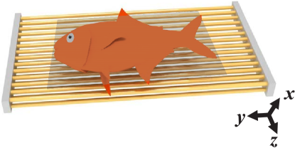
Here we demonstrate how 1.5 T MRI scanning efficiency is improved when the wire metamaterial-based surface (metasurface) structure is placed inside the scanner. Metasurfaces were studied by many groups Holloway et al. (2012); Kildishev et al. (2013) and have shown spectacular applications in the long-wavelength regime for communication Holloway et al. (2012) and in optics to control the propagation of light and to provide subwavelength imaging Yu et al. (2011); Zhao et al. (2012). We propose a metasurface, based on the resonant array of metallic wires, that is inserted into the water based holder [Fig. 1]. We demonstrate that this metasurface can controllably redistribute the RF electromagnetic field at deep subwavelength level and simultaneously increases the SNR more than twice. The immediate result of this increase is that a higher resolution image can be obtained over the same time slot or faster examination can be performed with similar resolution. Such metasurface presents a substantial step towards the improvement of MRI systems that are widely available in hospitals, without increasing the static magnetic field .
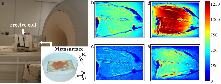
Our main results and experimental setup are summarized in Fig. 2. We have realized a metasurface as an array of wires. The studied biological sample (ex vivo fish) has been placed on the metasurface structure, embedded inside the water phantom, see the inset of Fig. 2a, and placed in a 1.5 T MR scanner, that has operating frequency 63.8 MHz [Fig. 2a]. The birdcage coil, which resides in the bore of the scanner, has been used as a transmitting antenna see Supplementary Materials and Methods for more details. The radio frequency signal has been received by a surface body array. The scans have been performed according to the standard magnetic resonance imaging protocol (see Methods). Panels (b)-(e) summarize the obtained results. Fig. 2b and Fig. 2c present the images obtained without the metasurface structure for the long scanning time of s (b) and for the short time of s (c). The SNR ratio is clearly increased for longer scanning time due to the accumulation of the signal. Panels (d) and (e) present the scans obtained for the fish placed on the metasurface for the long ( s) and short ( s) scanning time correspondingly. The amount of received valuable signal has substantially increased with the metamaterial [cf. Fig. 2b,c and Fig. 2d,e]. Moreover the amount of received signal for the short time with metasurface is comparable with that for longer time without the metamaterial [cf. Fig. 2b and Fig. 2e]. Hence, Fig. 2 indicates, that it is possible to achieve higher signal and better image quality at lower scan time. Due to the fact that MRI image quality is evaluated by SNR, we have performed more detailed experiments and quantitative numerical simulations, discussed below.
First, we have made experimental measurements of the SNR in the region of interest (see the black plane of Fig. 1) under the metasurface. Based on results of the separate scans of signal and noise in two configurations (phantom with the metasurface with and w/o the RF pulse and empty phantom with and w/o the RF pulse) we determined the ratio SNRSNR, where SNR2 corresponds to the ratio with the metasurface inside the phantom and SNR1 corresponds to the ratio for the empty phantom (see Supplementary Materials for more details). The increase of the SNR by more than a factor of two effectively corresponds using an MR system with a two times higher static magnetic field. Here, it is possible to improve MRI characteristics just putting the sample on the metasurface, without using the high field scanners.
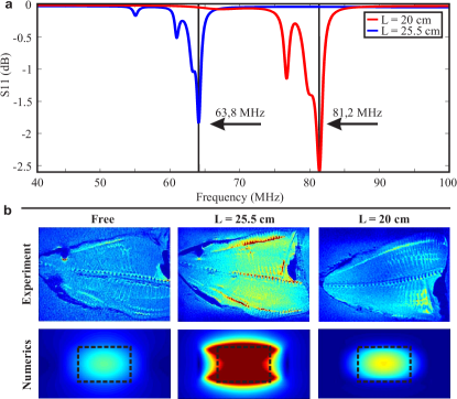
The enhancement of the signal with addition of metamaterial (Fig. 2d,e) is due to the resonant coupling to electromagnetic modes of the metasurface. The length of each wire is tuned to the Fabry-Pérot condition for the first eigenmode at the operating frequency of 1.5 T MRI machine, i.e. MHz. Here, is the dielectric constant of the background media, water in our case, and cm is the wire length. For the first Fabry-Perot mode the highest magnetic field is localized in the middle part of the surface and the electric field is localized near the edges of the wires Slobozhanyuk et al. (2013); Lemoult et al. (2012). Hence, the observed effect can be explained by the RF magnetic field enhancement on the wire metasurface. In particular, the SNR ratio is determined as a ratio of the RF magnetic field in the scanned region (a signal) to the square root of the absorbed power (a noise) Kuperman (2000). The Fabry-Perot resonance leads not only to the overall enhancement of both field and noise in the phantom, but it pins also the magnetic field to the scanned region suppressing the electric field and, hence, the absorbed power in this region. Such a relative redistribution of the spatial fields leads to a growth of SNR. It should be mentioned that the metasurface enhances also the transmitted RF magnetic field (see Supplementary Materials and Methods for more details).
To further confirm that the MRI enhancement of the SNR is mediated by the Fabry-Perot modes of the metasurface, we have compared experimentally and numerically two prototypes with different wire lengths cm and cm. In order to determine the working frequency of metamaterial in numerical simulation we have placed a small magnetic loop as a source under the metasurface in the center and analyzed the source reflection coefficient . The loop was located at 1.2 cm distance from the surface of the metamaterial. The minimum of the reflection coefficient is reached at the metasurface resonance, when the power is efficiently transmitted to the metasurface. In our case this takes place at the frequency of the first eigenmode of the metasurface. Red and blue curves in Fig. 3 correspond to the reflection coefficient of the antenna for different wire lengths, cm (blue) and cm (red). The Fabry-Perot mode frequency and the minimum of the reflection coefficient exhibit red shift for longer wires. The Fabry-Perot resonance of the structure with longer wires is tuned to the nuclear magnetic resonance at MHz. This explains the observed enhancement of the MRI image, as shown in the middle column of Fig. 3b. For shorter wires, the Fabry-Perot resonance is detuned. The image quality measured for this structure is much weaker (see the right column in Fig. 3b) and very similar to the results of the scanning of the fish without a metasurface (see the left column in Fig. 3b). The subtle difference between the images without a metamaterial and with a short metasurface can be explained due to the excitation of different transverse modes of a finite metamaterial sample at the frequencies below the Fabry-Perot resonance Slobozhanyuk et al. (2014). The excitation of these modes leads to the redistribution of the electromagnetic field and a slight enhancement of SNR (see the right bottom panel in Fig. 3b). For even shorter wires this effect will be minimized further at the 1.5 T operational frequency and no difference between scans with short wires and without metamaterial is observed. Therefore, the detuned metasurface does not influence the imaging process. Thus, Fig. 3b conclusively demonstrates, that the experimentally observed MRI enhancement is due to the spectral matching between the first Fabry-Perot mode of the metasurface and the frequency of the nuclear magnetic resonance.
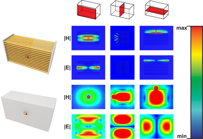
The safety aspects in MRI are mainly determined by the specific absorption ratio, that quantifies the absorption of electromagnetic energy and therefore the risk of tissue heating due to the application of the RF pulses, necessary to produce the MR signal. The specific absorption ratio is proportional to the square of the induced electric field. The electric field on the surface of the metamaterial is concentrated at the edges of the wires (see the absolute value of electric field induced on the top of the metasurface Fig. 4) and has an area of minimum values in the region of interest. Therefore, as soon as the object is placed on the resonator in a proper way the examination is safe and even safer than without resonator. In our case the optimal region coincides with the region of interest (black rectangular plane in Fig. 1) that is equal to 67% of the resonator length (see Supplementary Materials for detailed discussion). This metasurface resonator provides the possibility to homogeneously enhance and redistribute the RF field in such a way, that the magnetic field is located in the area of the object and the electric field is removed from the region of interest. Moreover, due to the low electric field region the SNR enhancement does not depend on the different tissue permittivities of various bodies. Also, the enhancement principle differs qualitatively from the earlier demonstrated metamaterial designs, mainly used to transmit an RF signal from the MRI tube or as a matching device between a coil and a patientWiltshire et al. (2001); Radu et al. (2009); Freire et al. (2008). Here, we enhance locally only the magnetic field in the scanned region while keeping the electric field and the SAR low. Although a metasurface made of split-ring resonatorsFreire et al. (2008) could be employed potentially in the similar regime, it suffers from stronger electric field and more inhomogeneous magnetic field in the imaged area. Hence, the proposed structure is more advantageous for a number of reasons.
With a view to underline the advantages of the metasurface resonator we have compared the proposed structure with the conventional high-permittivity resonator. The intrinsic property of the solutions to the Maxwell equations in the homogeneous medium is the coincidence between the antinodes of the magnetic field and the nodes of the electric one. Hence, it is impossible to maximize the RF magnetic field at the surface of the dielectric resonator while keeping the electric field away from the object under examination. We have numerically studied a bulk rectangular dielectric resonator with parameters tuned to obtain the first mode at the same frequency MHz. In order to excite the resonator we have placed a magnetic loop antenna in the center near the surface (see bottom left corner of Fig. 4). For qualitative comparison we have increased the number of layers in the metamaterial, so that the bulk dielectric resonator and the metamaterial resonator have approximately the same dimensions and are excited identically (see left corner of Fig. 4). Importantly, the metasurface behaves as a bulk wire metamaterial already for two or more layers of wires Slobozhanyuk et al. (2014).
As can be seen in Fig. 4, for a wire metamaterial resonator (top panels) the magnetic field is always localized at the resonator surface, while for a dielectric resonator (bottom panels) the magnetic field is localized inside the high permittivity structure, and electric field is localized at the surface. That is why the dielectric resonator can be employed only in the case when the object under study is placed inside of a high-permittivity resonator, which seems to be quite challenging.
We have realized an unique metamaterial resonator in the form of a wire metasurface. The Fabry-Perot resonance of the wire array is spectrally tuned to the nuclear magnetic resonance. This allows us to observe a substantial enhancement of the signal-to-noise ratio enabling a reduction of the MRI scanning time and also obtain higher image resolutions. Also it provides an opportunity to locally control the electric and magnetic fields near the object. There exists quite a number of possible implementations of metasurfaces for medical examinations inspired by the concepts of smart clothes and wearable electronics (see Supplementary Materials for details). For example, metal strips can be printed on clothes, so that a patient will have to wear a special lightweight jacket before the examination. In this particular case, the metasurface produces a homogeneous excitation from all sides. This involves no health risks provided that the strip ends are isolated from the patient, while it gives a possibility to use any desirable radio-frequency coils positioned near the patient. The metasurface can be embedded in certain parts of the patient table as well. To summarize, the use of metasurface is a promising pathway to improve the MRI efficiency and design simple yet effective scanning protocols.
Methods
All experiments were performed using a 1.5 T whole-body MRI system (Philips Healthcare) in combination with the 16 channel Torso XL receive array. The fish was located inside the water phantom and the receive array was placed around the water phantom (Fig. 2a). Two identical measurements (with the same position of the receiving coil) were performed: (1) a fish inside the water phantom without a metasurface; (2) a fish inside water phantom on a metasurface.
The metasurface was made from nonmagnetic brass wires. Wire length , radius and lattice period are equal to cm, cm and cm, respectively. The wires were supported by a double-layer plastic film, fillable by water. The period of the structure was optimized to achieve a homogeneous magnetic field enhancement in the region of interest. The number of layers was chosen to reach the highest magnetic field enhancement, while keeping the thickness of the structure as thin as possible.
Initially, we have determined by the direct measurements of the map that there is no influence of the metasurface on the main static magnetic field of MRI. The scans shown in Fig. 2 were obtained using a standard spin-echo sequence, with the following parameters: field of view was 300 mm by 300 mm, flip angle was , the echo time (TE) was 20 ms, for long time scans (Fig. 2b,d) the repetition time (TR) was 1240 ms and for short scan time (Fig. 2c,e) the TR was 480 ms. For SNR measurements we obtained separate data for signal and noise. The measurement sequence was carried out twice: the first time with the RF pulses and therefore acquiring signals and noise and the second time without any RF pulses and therefore acquiring only noise. The signal was defined as the mean pixel intensity value in a region of interest, while the noise was defined as the standard deviation in this region in the noise image. For this measurement we used gradient-echo sequence (GRE), the flip angle was , the TR was 50 ms and TE was 3.7 ms. After an addition of the metamaterial, the RF power levels that previously generated excitation pulses in the region of interest created a much larger angle due to enhancement of the RF field. In order to avoid over-tipping with metasurface present, the power level of the excitation pulses were re-optimized (reduced).
Numerical simulations were performed using the time-domain solver of CST Microwave Studio 2013 package. The small brass ring, excited by the discrete port (see red triangle in the left schematic plots of Fig. 4) was used as a source.
Acknowledgements
The authors are grateful to M. Kozlov, A.V. Shchelokova, M. Lapine, M. Barth, J.D. Baena, A.E. Miroshnichenko, I.V. Shadrivov, D.A. Powell, C.R. Simovski, and S.A. Tretyakov for useful discussions and suggestions. This work was supported by Government of Russian Federation (Grant 074-U01), Dynasty Foundation (Russia), and the Australian Research Council. ANP has been supported by the European Commission project “SPANGL4Q”.
Author Contributions
Numerical analysis was carried out by A.P.S and experiments were carried out by A.P.S., A.J.E.R., C.A.T.v.d.B., I.A.D and A.V.K. All authors analyzed and discussed the results. The manuscript and figures were prepared by A.P.S. and A.N.P.
References
- Lauterbur (1973) P. C. Lauterbur, Nature 242, 190 (1973).
- Hendee (1999) W. R. Hendee, Rev. Mod. Phys. 71, S444 (1999).
- Logothetis (2008) N. K. Logothetis, Nature (London) 453, 869 (2008).
- Ma et al. (2013) D. Ma, V. Gulani, N. Seiberlich, K. Liu, J. Sunshine, J. Duerk, and M. Griswold, Nature 495, 187 (2013).
- Degen et al. (2009) C. L. Degen, M. Poggio, H. J. Mamin, C. T. Rettner, and D. Rugar, PNAS 106, 1313 (2009).
- Bajaj et al. (2010) V. S. Bajaj, J. Paulsen, E. Harel, and A. Pines, Science 330, 1078 (2010).
- Niendorf et al. (2013) T. Niendorf, A. Graessl, C. Thalhammer, M. A. Dieringer, O. Kraus, D. Santoro, K. Fuchs, F. Hezel, S. Waiczies, B. Ittermann, and L. Winter, Journal of Magnetic Resonance 229, 208 (2013).
- Haacke et al. (1999) E. M. Haacke, R. W. Brown, M. R. Thompson, and R. Venkatesan, Magnetic Resonance Imaging: Principles and Sequence Design. (Wiley, 1999).
- Tanenbaum (2006) L. N. Tanenbaum, Magnetic Resonance Imaging Clinics of North America 14, 1 (2006).
- Vaughan et al. (2006) T. Vaughan, L. DelaBarre, C. Snyder, and et al., Magn. Reson. Med. 56, 1274 (2006).
- Theysohn et al. (2009) J. M. Theysohn, O. Kraff, S. Maderwald, M. Schlamann, A. de Greiff, M. Forsting, S. Ladd, M. Ladd, and E. Gizewski, Hippocampus 19, 1 (2009).
- Truong et al. (2006) T.-K. Truong, D. W. Chakeres, D. Q. Beversdorf, D. W. Scharre, and P. Schmalbrock, Magnetic resonance imaging 24, 103 (2006).
- Stafford (2005) R. J. Stafford, Medical Physics 32, 2077 (2005).
- Wood et al. (2012) R. Wood, K. Bassett, V. Foerster, C. Spry, and L. Tong, CADTH Technology Overviews 2, e2201 (2012).
- Kanal et al. (2013) E. Kanal, A. J. Barkovich, C. Bell, and et al., Journal of Magnetic Resonance Imaging 37, 501 (2013).
- Sodickson and Manning (1997) D. K. Sodickson and W. J. Manning, Magn. Reson. Med. 38, 591 (1997).
- Pruessmann et al. (1999) K. P. Pruessmann, M. Weiger, M. B. Scheidegger, and P. Boesiger, Magn. Reson. Med. 42, 952 (1999).
- Roemer et al. (1990) P. B. Roemer, W. A. Edelstein, C. E. Hayes, S. P. Souza, and O. M. Mueller, Magn. Reson. Med. 16, 192 (1990).
- Brunner et al. (2009) D. Brunner, N. De Zanchei, J. Frohlich, J. Paska, and K. Pruessmann, Nature 457, 994 (2009).
- Andreychenko et al. (2013) A. Andreychenko, H. Kroeze, D. W. J. Klomp, J. J. W. Lagendijk, P. R. Luijten, and C. A. T. van den Berg, Magn. Reson. Med. 70, 875 (2013).
- Kuperman (2000) V. Kuperman, Magnetic Resonance Imaging. Physical Principles and Applications (Academic Press, San Diego, 2000).
- Thierry et al. (2005) B. Thierry, S. Faghihi, L. Torab, G. Pike, and M. Tabrizian, Adv. Mater. 17, 826 (2005).
- Högemann et al. (2000) D. Högemann, L. Josephson, R. Weissleder, and J. P. Basilion, Bioconjugate Chemistry 11, 941 (2000).
- Yang et al. (2011) Q. X. Yang, J. Wang, J. Wang, C. M. Collins, C. Wang, and M. B. Smith, Magn. Reson. Med. 65, 358 (2011).
- Aussenhofer and Webb (2012) S. A. Aussenhofer and A. G. Webb, Magn. Reson. Med. 68, 1325 (2012).
- Aussenhofer and Webb (2013) S. A. Aussenhofer and A. G. Webb, NMR in Biomedicine (2013), 10.1002/nbm.2990.
- Engheta and Ziolkowski (2006) N. Engheta and R. W. Ziolkowski, eds., Metamaterials: Physics and Engineering Explorations (Wiley-IEEE Press, 2006).
- Cai and Shalaev (2010) W. Cai and V. Shalaev, Optical Metamaterials: Fundamentals and Applications (Springer, New York, 2010).
- Wiltshire et al. (2001) M. C. K. Wiltshire, J. B. Pendry, I. R. Young, D. J. Larkman, D. J. Gilderdale, and J. V. Hajnal, Science 291, 849 (2001).
- Freire et al. (2008) M. J. Freire, R. Marques, and L. Jelinek, Appl. Phys. Lett. 93, 231108 (2008).
- Freire et al. (2010) M. J. Freire, L. Jelinek, R. Marques, and M. Lapine, Journal of Magnetic Resonance 203, 81 (2010).
- Syms et al. (2010) R. Syms, T. Floume, I. Young, L. Solymar, and M. Rea, Metamaterials 4, 1 (2010).
- Radu et al. (2009) X. Radu, D. Garray, and C. Craeye, Metamaterials 3, 90 (2009).
- Holloway et al. (2012) C. Holloway, E. F. Kuester, J. Gordon, J. O’Hara, J. Booth, and D. Smith, IEEE Antennas and Propogat. Mag. 54, 10 (2012).
- Kildishev et al. (2013) A. V. Kildishev, A. Boltasseva, and V. M. Shalaev, Science 339 (2013).
- Yu et al. (2011) N. Yu, P. Genevet, M. A. Kats, F. Aieta, J.-P. Tetienne, F. Capasso, and Z. Gaburro, Science 334, 333 (2011).
- Zhao et al. (2012) Y. Zhao, M. A. Belkin, and A. Alù, Nat. Commun 3 (2012).
- Slobozhanyuk et al. (2013) A. P. Slobozhanyuk, I. V. Melchakova, C. R. Simovski, and P. A. Belov, Appl. Phys. Lett. 103, 051118 (2013).
- Lemoult et al. (2012) F. Lemoult, M. Fink, and G. Lerosey, Nat. Commun. 3, 889 (2012).
- Slobozhanyuk et al. (2014) A. P. Slobozhanyuk, A. N. Poddubny, A. E. Krasnok, and P. A. Belov, Appl. Phys. Lett. 104, 161105 (2014).