Coherent 100G Nonlinear Compensation with Single-Step Digital Backpropagation
Abstract
Enhanced-SSFM digital backpropagation (DBP) is experimentally demonstrated and compared to conventional DBP. A 112 Gb/s PM-QPSK signal is transmitted over a 3200 km dispersion-unmanaged link. The intradyne coherent receiver includes single-step digital backpropagation based on the enhanced-SSFM algorithm. In comparison, conventional DBP requires twenty steps to achieve the same performance. An analysis of the computational complexity and structure of the two algorithms reveals that the overall complexity and power consumption of DBP are reduced by a factor of 16 with respect to a conventional implementation, while the computation time is reduced by a factor of 20. As a result, the proposed algorithm enables a practical and effective implementation of DBP in real-time optical receivers, with only a moderate increase of the computational complexity, power consumption, and latency with respect to a simple feed-forward equalizer for dispersion compensation.
Index Terms:
fiber-optic systems; fiber nonlinearity; digital backpropagationI Introduction
Digital backpropagation (DBP) is one of the most studied strategies to counteract nonlinearities by channel inversion [1]. Due to both technological and practical reasons, DBP is typically used only to compensate for intra-channel nonlinearity. Though most effective for combating nonlinear signal-signal interactions, DBP is also a key element for the realization of nearly optimum detectors (accounting also for signal-noise interaction) when combined to a Viterbi processor for maximum likelihood sequence detection [2], or applied to particle filtering for stochastic backpropagation [3]. In practice, DBP is implemented through the split-step Fourier method (SSFM), probably the most efficient numerical method known to simulate fiber-optic propagation [4]. The SSFM allows for complexity versus accuracy trade-off by adjusting the number of steps and takes advantage of the high computational efficiency of the fast Fourier transform algorithm. Nevertheless, the computational complexity, latency, and power consumption required by DBP in typical long-haul systems are significantly higher than those required by other digital signal processing blocks (e.g., linear equalizers) and still pose some difficulties to its implementation in a real-time digital receiver. Several approaches have been proposed to obtain good trade-offs between complexity and performance [5, 6]. Based on heuristic approaches, some modifications of the SSFM algorithm have been also proposed to reduce complexity without sacrificing accuracy [7, 8, 9, 10]. However, some approximate solutions of the nonlinear Schrödinger equation are available in the literature and could be exploited for improving the SSFM algorithm [11, 12, 13, 14]. While the Volterra series [11] and regular perturbation [12] approaches describe the nonlinearity as an additive perturbation and do not appear to be suitable, the logarithmic approximation [13, 14] gives an expression which is closer to that used in the SSFM method for approximating the nonlinear propagation in a piece of fiber but more accurate. Based on the logarithmic perturbation technique, an enhanced SSFM (ESSFM) has been recently proposed and, through numerical simulations, it was shown to have a one order of magnitude lower complexity compared to the standard SSFM for a prescribed accuracy [15].
In this work, we extend the ESSFM algorithm to account for the propagation of a polarization-multiplexed signal and experimentally demonstrate its effectiveness for the implementation of DBP within a coherent optical receiver. In particular, we compare the SSFM and ESSFM algorithms to backpropagate a 112 Gb/s PM-QPSK signal through a 3200 km dispersion-unmanaged link, showing that the ESSFM provides a significant reduction of complexity, latency, and power consumption. The paper is organized as follows. In Section II, we describe the ESSFM algorithm. In Section III, we investigate the computational complexity, computational time (latency), and power consumption of the proposed ESSFM algorithm and compare them to those of the conventional SSFM and of a simple feed-forward equalizer (FFE) for dispersion compensation. In Section IV, we show the experimental results and the actual improvements obtained by employing the ESSFM. Finally, in Section V, we draw the conclusions.
II Enhanced split-step Fourier method
The propagation of a single-polarization optical signal through a fiber-optic link in the presence of chromatic dispersion, Kerr nonlinearity, and attenuation is governed by the nonlinear Schrödinger equation, which can be numerically solved by means of the SSFM algorithm. According to the SSFM, the link is divided into small segments (steps). Each step is further divided into two sub-steps: a linear sub-step, accounting for chromatic dispersion, and a nonlinear sub-step, accounting for a nonlinear phase rotation proportional to the signal intensity (Kerr nonlinearity). When considering polarization-multiplexed signals, the nonlinear Schrödinger equation is replaced by the Manakov equation [16]. In this case, the SSFM can be still employed by modifying the nonlinear sub-step to account for a nonlinear phase rotation on each polarization that is proportional to the overall signal intensity on both polarizations. In both cases, as processing for the linear and nonlinear sub-steps takes place in frequency and time domain, respectively, direct and inverse FFTs are used at each step to switch between the time and frequency representation of the signal. In practice, the propagation of a block of vector samples (where each vector collects the -th samples of the two signal polarizations) through a generic step of length , with dispersion coefficient , nonlinear coefficient , and attenuation coefficient , entails performing the following four operations: (i) computation of the frequency components through a pair of FFTs (one per each polarization); (ii) computation of the linear sub-step
| (1) |
where is the frequency of the -th component; (iii) computation of the time components through a pair of inverse FFTs; (iv) computation of the nonlinear sub-step
| (2) |
being the effective length. The output sequence becomes, in turn, the input to the next fiber segment and so on, until the end of the link is reached.
The overall complexity of the SSFM algorithm is mainly driven by the required FFTs and can be reduced by employing the ESSFM algorithm, which achieves the same accuracy as the SSFM with a lower number of steps [15]. The main idea behind the ESSFM is that of keeping the SSFM approach but modifying the nonlinear sub-step (2) to account also for the interaction between dispersion and nonlinearity along . In this way, can be increased (and, consequently, decreased) without affecting the overall accuracy. Of course, the overall complexity is reduced only if the new term is less costly than the spared FFTs. A more accurate expression for the nonlinear sub-step is provided by the frequency-resolved logarithmic perturbation (FRLP) method [17]. In particular, it can be shown that in the nonlinear step the signal undergoes a nonlinear phase rotation that depends on a quadratic form of the signal samples [18]. By truncating the channel memory to the first past and future samples, retaining only the diagonal terms of the quadratic form, and averaging the FRLP coefficients over the signal bandwidth, results in the modified nonlinear sub-step proposed in [15] (for a single-polarization signal) which, in analogy to the SSFM case, is simply extended to a polarization-multiplexed signal by considering a nonlinear phase rotation on each polarization that is the sum of the phase rotations induced by each polarization. The enhanced nonlinear sub-step is thus expressed as
| (3) |
where are real coefficients. Formally, (3) is equal to the nonlinear sub-step proposed in [15], but replacing scalar samples with vector samples. We also note that (3) is similar to the nonlinear sub-step proposed in [8, 10]. However, the coefficient values obtained through a logarithmic-perturbation analysis or numerical optimization, as discussed in [15], may be significantly different from the low-pass filter coefficients employed in [8, 10], thus providing a different performance.
III Computational complexity, latency, and power consumption
The hardest challenge for a real-time implementation of DBP is keeping its complexity, latency, and power consumption within feasible values. Though an accurate analysis of the computational complexity, latency, and power consumption for a real-time implementation of the SSFM and ESSFM algorithms is beyond the scope of this work—it depends on the actual implementation of the FFT and of the exponential operation, on the employed hardware, on the sampling rate, on the adopted precision, and so on—here we want to show that the number of steps is a reasonable figure of merit to compare the two algorithms and to provide a rough, yet meaningful, indication about their complexity, latency, and power consumption.
When processing a long sequence of samples through the SSFM or ESSFM algorithms, as required for instance when implementing DBP in a fiber-optic transmission system, the overlap-and-save technique is typically employed [19, 20]. The input sequence of samples is divided into several overlapping blocks which are separately processed, and the output sequence is then reconstructed by discarding the overlapping samples. The number of overlapping samples should be at least equal to the overall memory of the fiber-optic channel—which, for dispersion-uncompensated links, can be approximated as , where is the fiber dispersion parameter, the link length, and the signal bandwidth (assumed equal to the sampling rate)—while the block length should be optimized to minimize the computational cost per propagated sample. The propagation of each block of samples through each step of fiber requires: the computation of four FFTs (a pair of direct and inverse FFTs per polarization) of complex samples (about real multiplications and real additions)111We consider the classical Cooley-Tukey radix-2 FFT algorithm [21] and assume that each complex multiplication requires 4 real multiplications and 2 real additions. Though slightly more efficient implementations are possible, this provides a reasonable indication of the required operations. Moreover, we assume that all fixed quantities (e.g., or ) are precalculated and that the complex exponential in (3) is evaluated by using a lookup table.; the computation of the linear sub-step (1) ( real multiplications and real additions); the computation of the nonlinear sub-step (3), which in turn requires the computation of squared moduli ( real multiplications and real additions), their linear combination ( real multiplications and real additions), and the nonlinear phase shift rotation ( real multiplications and real additions, neglecting the cost of the complex exponential). Overall, considering that samples out of are discarded by the overlap-and-save algorithm, the ESSFM algorithm requires real multiplications and real additions per step per received sample. The complexity of the SSFM is exactly the same, with .
It is useful to make a comparison with the complexity of a linear feed-forward equalizer (FFE) for bulk dispersion compensation. This is typically implemented in frequency domain and is practically equivalent to a single step of the SSFM, in which only the linear sub-step is considered [22]: two parallel direct FFTs (one per polarization) of complex samples, the linear sub-step (1), and two parallel inverse FFTs. Overall, the FFE requires real multiplications and real additions per received sample.
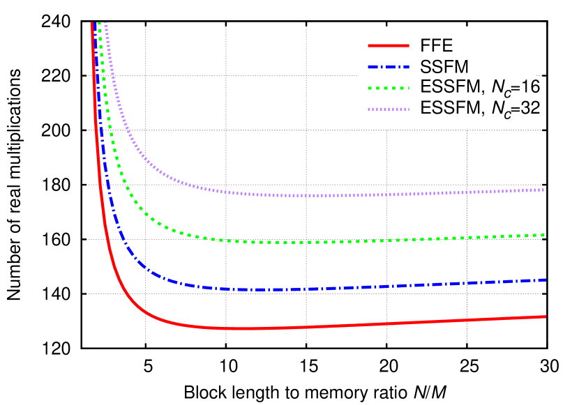
Given the memory of the channel, the block length can be optimized to minimize the complexity (e.g., number of additions and/or multiplications). As an example, considering a memory of samples—due, for instance, to the propagation of a 50 GHz signal through about 3000 km of standard single-mode fiber—Fig. 1 shows the number of real multiplications required by the FFE, by one step of the SSFM, and by one step of the ESSFM (with ) per each processed sample as a function of the ratio . As it is clear also from the expressions provided above, the optimum ratio depends on the considered algorithm and on the value of (and also on the value of , assumed fixed in Fig. 1). However, it can be observed that by setting , one obtains nearly minimum complexity in all the considered cases. Lower values of would reduce latency, but at the expense of a significantly higher complexity. On the other hand, higher values of would only slightly reduce complexity, but at the expense of a higher latency. A similar result is obtained also when considering the number of real additions and different values of and (within a reasonable range of practical interest). Therefore, in the following, we will always consider .
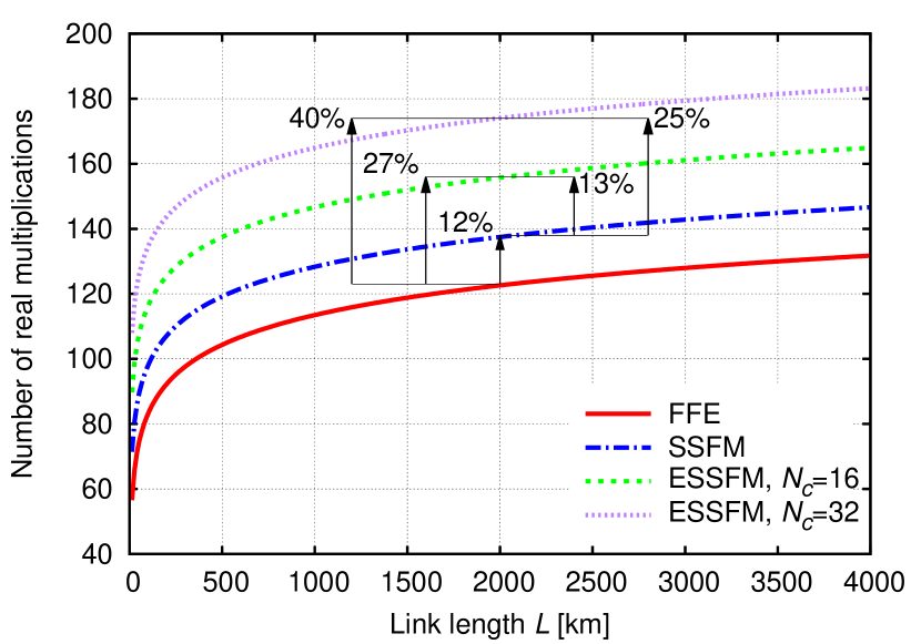
Given this choice, it is interesting to compare the complexity of the various algorithms and see how it changes with link length. Fig. 2 reports the number of real multiplications per processed sample for the FFE, SSFM, and ESSFM with different values of as a function of the link length . A standard single-mode fiber () and a 50 GHz signal bandwidth are considered. Note, again, that only one step of SSFM or ESSFM is considered, and that their overall complexity is thus obtained by multiplying the values in Fig. 1 or 2 by the total number of steps . As shown in the figure, at 2000 km each step of the ESSFM with is about 25% more complex than the SSFM and 40% more complex than the FFE. These figures remain almost unchanged at longer distances, slightly increase at shorter distances, and decrease when considering a lower number of coefficients .
When considering a real-time implementation of the algorithms in an optical receiver, the resulting power consumption is an important figure of merit. Power consumption depends on the actual hardware implementation, processing rate, and considered technology and its accurate and absolute estimate is beyond the scope of this work. However, we can reasonably assume that, once all these parameters are fixed, power consumption scales approximately as computational complexity. Therefore, we can use Fig. 2 also to compare the power consumption of the various algorithms and infer that each step of the ESSFM (with ) requires about 25% more power than each step of the SSFM, and about 40% more power than the FFE.

Finally, also the latency due to the different algorithms is of fundamental importance for their real-time implementation. In this case, as almost all the filtering operations involved in the nonlinear sub-step (3) can be executed in parallel, we can assume that the latency of the ESSFM is almost independent of and equal to the latency of the SSFM. Moreover, the latency due to the whole nonlinear sub-step can be considered negligible compared to that due to the FFT. Therefore, we can assume that the total latency of the three algorithms depends on the total number of cascaded FFTs (a pair for the FFE and pairs for the SSFM and ESSFM ) and on their size (equal to the block length , which depends on the link length and is the same for all the algorithms ). Again, an absolute and accurate estimate of the latency is beyond the scope of this work. However, we can compare the various algorithms by assuming that the latency induced by each step of the SSFM or ESSFM equals that induced by the FFE.
In conclusion, the required number of steps can be taken as a meaningful figure of merit to measure the complexity, latency, and power consumption of the SSFM and ESSFM algorithms: taking a simple FFE for bulk dispersion compensation (in dispersion-unmanaged links) as a basis for comparison, the latency of the SSFM and ESSFM is about times that of the FFE, while their complexity and power consumption are slightly more than times that of the FFE, as indicated in Fig. 2. Therefore, a saving in the number of steps provided by the ESSFM compared to the SSFM (as experimentally demonstrated in the next section) translates into a proportional saving in terms of latency, and an almost proportional saving in terms of complexity and power consumption.
IV Experimental results
The experimental setup employed to compare the performance of the SSFM and ESSFM algorithms is depicted in Fig. 3. An optical carrier, generated by a 100 kHz-linewidth tunable laser source (TLS), is modulated by means of an integrated double nested Mach Zehnder modulator (IQ-MZM). Two PRBS signals of length at are applied to the in-phase (I) and quadrature (Q) port of the modulator to obtain a 56 Gb/s QPSK optical signal. Polarization multiplexing is finally emulated through a 50/50 beam splitter, an optical delay, and a polarization beam combiner (PBC), obtaining a 112 Gb/s PM-QPSK optical signal. A recirculating loop is used to emulate transmission over long distances. The loop is composed by two spans of 40 km of standard single-mode fiber, each one followed by an erbium-doped fiber amplifier (EDFA). A gain equalization filter (GEF) is used to equalize the distortions due to the amplifier gain profile and a polarization scrambler (POL-S) is included in the loop to emulate random polarization rotations along the link. At the receiver, the optical signal is detected by employing coherent phase- and polarization-diversity detection and setting the local oscillator (LO) at the same nominal wavelength of the transmitter TLS (with accuracy). The received optical signal is mixed with the LO through a polarization-diversity 90° hybrid optical coupler, whose outputs are sent to four couples of balanced photodiodes. The four photodetected signals are sampled and digitized through a 20 GHz 50 GSa/s real-time oscilloscope in separate blocks of one million samples at a time. Each block of samples is processed off-line according to the scheme of Fig. 3. Bulk dispersion compensation (with a frequency-domain FFE) or DBP based on the SSFM or ESSFM algorithm is performed on signal samples taken at the original sampling rate (about 1.8 sample per symbol). Then, after digital resampling at two samples per symbol, a butterfly equalizer is employed to adaptively compensate for polarization mode dispersion and residual chromatic dispersion. Finally, asynchronous detection is employed (at symbol rate) to account for phase noise and a possible frequency offset and to make decisions as in [23]. The first 100000 received samples are used to optimize the ESSFM coefficients, while bit-error rate (BER) is measured on the remaining samples. The ESSFM coefficients are optimized by using the output of the SSFM algorithm with multiple steps/span as a target and minimizing the mean square error (MSE) with respect to it.222This approach can be employed even in a real system, as the optimization can be done off-line when designing the link. A more practical (and possibly accurate) approach is that of minimizing the MSE between the output samples (after DBP, equalization, and phase-noise/frequency-offset compensation) and the transmitted symbols, as suggested in [15]. This, however, needs some care to handle possible interactions with the convergence of the butterfly equalizer and is left to a future investigation. BER values are finally obtained by averaging over 5 different blocks of samples.
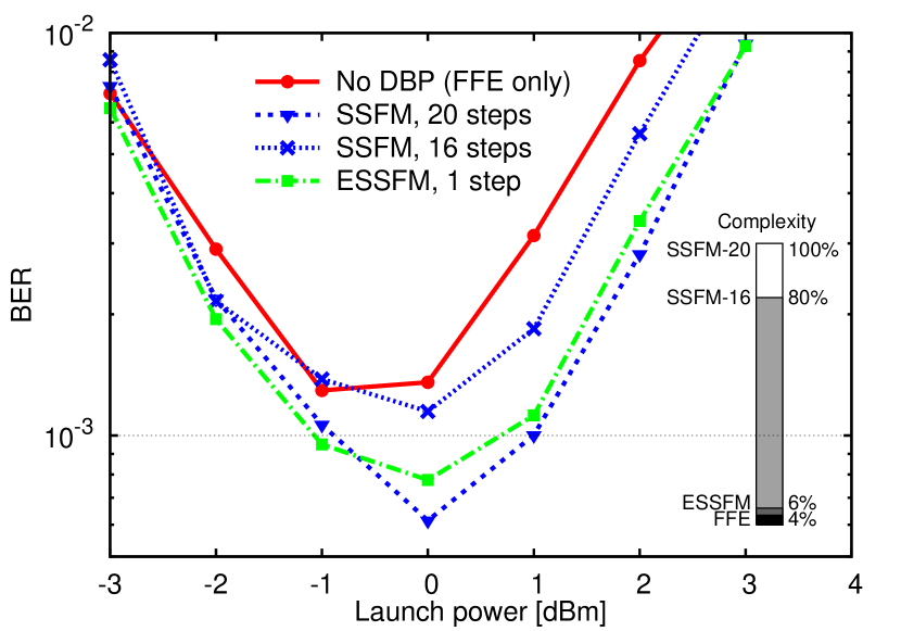
The performance and complexity of the SSFM and ESSFM algorithm are compared at a transmission distance of 3200 km, at which the system operates with a BER above an arbitrary prescribed threshold of without DBP (with FFE only). The BER versus launch power obtained without DBP (replaced by the FFE for dispersion compensation), with the SSFM, and with the ESSFM algorithm is shown in Fig. 4. At this distance, a channel memory samples and a nearly optimal FFT size are taken. Different number of steps for the SSFM and ESSFM algorithms are considered. For the ESSFM algorithm, is selected to provide a good trade-off between performance and complexity. For the system without DBP, the minimum BER is obtained at a launch power of -1 dBm and is higher than the prescribed threshold. When including DBP based on the standard SSFM algorithm, at least 20 steps (one step each four spans) are required to obtain (at a launch power of 0 dBm). On the other hand, when the ESSFM algorithm is used to implement DBP, the prescribed BER can be achieved (already at -1 dBm of launch power) with just a single step for the whole link and coefficients. The total number of real multiplications per received sample is 128 for the FFE, 179 for the ESSFM, 2286 for the 16-step SSFM, and 2857 for the 20-step SSFM. The relative complexity (and power consumption) of the various algorithms is shown in the inset of Fig. 4, taking the 20-step SSFM as a reference. By employing the ESSFM, the overall complexity and power consumption are reduced by a factor of 16 with respect to a conventional SSFM with the same performance, and latency by a factor of 20.
V Conclusions
Low-complexity DBP based on the ESSFM algorithm has been experimentally demonstrated by backpropagating a 112 Gb/s PM-QPSK signal through a 3200 km dispersion-unmanaged link. A target BER of has been achieved with a single DBP step, with a 16 times lower complexity and 20 times lower latency than conventional DBP. This means that ESSFM allows for complexity, latency, and power-consumption comparable with those required by standard feedforward equalization for chromatic dispersion compensation.
Acknowledgment
This work was supported in part by the Italian MIUR under the FIRB project COTONE and by the EU FP-7 GÉANT project COFFEE.
References
- [1] E. Ip and J. M. Kahn, “Compensation of dispersion and nonlinear impairments using digital backpropagation,” J. Lightwave Technol., vol. 26, no. 20, pp. 3416–3425, 2008.
- [2] D. Marsella, M. Secondini, and E. Forestieri, “Maximum likelihood sequence detection for mitigating nonlinear effects,” J. Lightwave Technol., vol. 32, no. 5, pp. 908–916, 2014.
- [3] N. V. Irukulapati, D. Marsella, P. Johannisson, M. Secondini, H. Wymeersch, E. Agrell, and E. Forestieri, “On maximum likelihood sequence detectors for single-channel coherent optical communications,” in European Conf. on Optical Commun. (ECOC), p. P.3.19, 2014.
- [4] T. R. Taha and M. J. Ablowitz, “Analytical and numerical aspects of certain nonlinear evolution equation, II, numerical, nonlinear Schroedinger equation,” J. Computat. Phys., vol. 5, pp. 203 – 230, 1984.
- [5] G. Goldfarb and G. Li, “Efficient backward-propagation using wavelet-based filtering for fiber backward-propagation,” Optics Express, vol. 17, no. 11, pp. 8815–8821, 2009.
- [6] R. Asif, C.-Y. Lin, M. Holtmannspoetter, and B. Schmauss, “Optimized digital backward propagation for phase modulated signals in mixed-optical fiber transmission link,” Optics Express, vol. 18, no. 22, pp. 22796–22807, 2010.
- [7] L. B. Du and A. J. Lowery, “Improved single channel backpropagation for intra-channel fiber nonlinearity compensation in long-haul optical communication systems,” Optics Express, vol. 18, no. 16, pp. 17075–17088, 2010.
- [8] L. Li, Z. Tao, L. Dou, W. Yan, S. Oda, T. Tanimura, T. Hoshida, and J. C. Rasmussen, “Implementation efficient nonlinear equalizer based on correlated digital backpropagation,” in Opt. Fiber Commun. Conf. (OFC), p. OWW3, 2011.
- [9] E. Ip, N. Bai, and T. Wang, “Complexity versus performance tradeoff for fiber nonlinearity compensation using frequency-shaped, multi-subband backpropagation,” in Opt. Fiber Commun. Conf. (OFC), p. OThF4, 2011.
- [10] D. Rafique, M. Mussolin, M. Forzati, J. Mårtensson, M. N. Chugtai, and A. D. Ellis, “Compensation of intra-channel nonlinear fibre impairments using simplified digital back-propagation algorithm,” Optics Express, vol. 19, no. 10, pp. 9453–9460, 2011.
- [11] K. V. Peddanarappagari and M. Brandt-Pearce, “Volterra series transfer function of single-mode fibers,” J. Lightwave Technol., vol. 15, pp. 2232–2241, 1997.
- [12] A. Vannucci, P. Serena, and A. Bononi, “The RP method: a new tool for the iterative solution of the nonlinear Schrödinger equation,” J. Lightwave Technol., vol. 20, pp. 1102–1112, July 2002.
- [13] E. Ciaramella and E. Forestieri, “Analytical approximation of nonlinear distortions,” IEEE Photon. Technol. Lett., vol. 17, pp. 91–93, Jan. 2005.
- [14] E. Forestieri and M. Secondini, “Solving the nonlinear Schrödinger equation,” in Optical Communication Theory and Techniques (E. Forestieri, ed.), pp. 3–11, New York: Springer, 2004.
- [15] M. Secondini, D. Marsella, and E. Forestieri, “Enhanced split-step fourier method for digital backpropagation,” in Proc. European Conf. on Optical Commun. (ECOC), p. We.3.3.5, 2014.
- [16] C. Menyuk and B. Marks, “Interaction of polarization mode dispersion and nonlinearity in optical fiber transmission systems,” J. Lightwave Technol., vol. 24, pp. 2806–2826, July 2006.
- [17] M. Secondini and E. Forestieri, “Analytical fiber-optic channel model in the presence of cross-phase modulation,” IEEE Photon. Technol. Lett., vol. 24, pp. 2016–2019, nov 2012.
- [18] M. Secondini, E. Forestieri, and G. Prati, “Achievable information rate in nonlinear WDM fiber-optic systems with arbitrary modulation formats and dispersion maps,” J. Lightwave Technol., vol. 31, no. 23, pp. 3839–3852, 2013.
- [19] T. G. Stockham Jr., “High-speed convolution and correlation,” in Proc. 1966 Spring Joint Computer Conf., AFIPS, vol. 28, pp. 229–233, 1966.
- [20] A. V. Oppenheim and R. W. Schafer, Discrete-Time Signal Processing. Upper Saddle River, New Jersey: Prentice Hall, 1999.
- [21] J.W. Cooley and J.W. Tukey, “An algorithm for the machine calculation of complex Fourier series,” Math. Comp., vol. 19, pp. 297–301, 1965.
- [22] M. Kuschnerov, F. N. Hauske, K. Piyawanno, B. Spinnler, M. S. Alfiad, A. Napoli, and B. Lankl, “DSP for Coherent Single-Carrier Receivers,” J. Lightwave Technol., vol. 27, pp. 3614–3622, 15 Aug. 2009.
- [23] F. Cugini, F. Paolucci, G. Meloni, G. Berrettini, M. Secondini, F. Fresi, N. Sambo, L. Poti, and P. Castoldi, “Push-pull defragmentation without traffic disruption in flexible grid optical networks,” J. Lightwave Technol., vol. 31, no. 1, pp. 125–133, 2013.