On-chip Maxwell’s demon as an information-powered refrigerator
Abstract
We present an experimental realization of an autonomous Maxwell’s Demon, which extracts microscopic information from a System and reduces its entropy by applying feedback. It is based on two capacitively coupled single electron devices, both integrated on the same electronic circuit. This setup allows a detailed analysis of the thermodynamics of both the Demon and the System as well as their mutual information exchange. The operation of the Demon is directly observed as a temperature drop in the System. We also observe a simultaneous temperature rise in the Demon arising from the thermodynamic cost of generating the mutual information.
Thermodynamic processes are governed by fundamental laws, of which the first, conservation of energy, is paramount in all fields of physics and cannot be violated at any level of description known to date. The Second Law in turn states that entropy, the measure of disorder, of a closed system cannot decrease. This has most important consequences, such that heat flows from hot to cold, irreversible processes must dissipate work, and devices of perpetual motion are impossible. To challenge this law, James Clerk Maxwell presented a thought experiment in 1867 of a “finite being” capable of accurately measuring the velocity of molecules Leff and Rex (2003). It would act between two separated reservoirs, permitting only fast molecules to enter one reservoir, while allowing only the slow ones to the other. Under such a process heat is transferred from cold to hot, apparently in violation of the Second Law. This idea, coined as ”Maxwell’s demon” by Lord Kelvin, has over a century spurred further research on the relation between information and energy establishing quantitative relations Szilard (1929); Landauer (1961, 1988); Sagawa and Ueda (2008, 2010); Mandal and Jarzynski (2012); Esposito and Schaller (2012); Deffner and Jarzynski (2013); Strasberg et al. (2014); Barato and Seifert (2014); Lutz and Ciliberto (2015). Ongoing progress in nanotechnology has also provided concrete means to test such relations experimentally Serreli et al. (2006); Price et al. (2008); Thorn et al. (2008); Raizen (2009); Toyabe et al. (2010); Bérut et al. (2011); Roldán et al. (2014); Koski et al. (2014a, b); Parrondo et al. (2015); Chida et al. (2015), thus re-igniting acute interest in actually constructing a Demon.
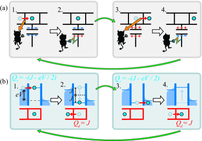
Recently, several theoretical proposals on configurations including both the System as well as the Demon have been presented Mandal and Jarzynski (2012); Barato and Seifert (2013); Strasberg et al. (2013); Shirashi et al. (2015). Such a configuration is known as an autonomous Maxwell’s demon, for the fact that the measurement and feedback operation takes place internally. Here, we experimentally realize an all-in-one Maxwell’s demon, whose operation principle is cartooned in Fig. 1 (a). The System is a single electron transistor (SET) Averin and Likharev (1986), formed by a small normal metallic island connected to two normal metallic leads by tunnel junctions. The two junctions permit electron transport by tunneling, and are assumed to be identical (both with the same resistance ). The Demon measures the number of electrons on the System island, and applies feedback as depicted in Fig. 1 (a). When an electron tunnels to the island, the Demon traps it with a positive charge (panels 1 and 2). Conversely, when an electron leaves the island, the Demon applies a negative charge to repel further electrons that would enter the island (panels 3 and 4). The System electrodes contain a reservoir of conduction electrons whose thermal excitations provide sufficiently high energy carriers to overcome the the trapping or repulsion induced by the Demon, contributing heat where is the energy cost of the tunneling event. In doing so, the System entropy decreases as , where is the System reservoir temperature, i.e. the Demon extracts information of tunneling electrons to apply feedback that causes the entropy of the System to decrease. While the configuration resembles theoretical proposals on quantum dots Sánchez and Büttiker (2012); Strasberg et al. (2013); Zhang et al. (2015), and shares features with the Coulomb drag effect Solomon et al. (1989); Averin et al. (1991), it constitutes a genuine autonomous Maxwell’s Demon where only information, not heat, is directly exchanged between the System and the Demon.
Our experimental, autonomous realization of the cycle in Fig. 1 (a) relies on coupling the System island capacitively to a single electron box (SEB), a small normal metallic island connected by a tunnel junction with resistance to a single normal metallic lead. Here, the SEB undertakes the role of the Demon. The resulting Hamiltonian is
| (1) |
where the dynamic variables and are the net number of electrons that have entered the System and the Demon islands, respectively. and are their charging energies, while describes their mutual Coulomb interaction and is essential for the device operation. The state evolves when an electron tunnels through a junction. changes to when an electron tunnels from (to) the System island. Correspondingly, changes to when it transfers from (to) the Demon island. Constant external control parameters and govern the System current and the coupling of the Demon to the System, respectively. The System is voltage biased, such that the electron (with elementary charge ) tunneling in the direction of (against) the voltage bias experiences an energy cost , where for changing is given by Eq. (1). Similarly, for the electron tunneling in the Demon .
The interaction between the System and the Demon is maximized by setting , producing the Hamiltonian and energetics depicted in Fig. 1 (b). We furthermore require , such that only the lowest energy states of Eq. (1) are available, such that both and are practically limited to two possible values, and . States and are charge neutral, both with energy . Here, we refer to either of the states as ’ground’ or . The state has an overall positive charge and an overall negative charge. We refer to them as ’charged’ or , both with energy . Any single tunneling event will take to or to , with respective . We assume that the System is at uniform temperature while the temperature of the Demon is , such that the occupation probability distribution obeys and with and . Here, with notation , the term is the overall transition rate from to , while is the corresponding overall transition rate from to as a sum of rates in the System in the direction of bias, against the bias, and the transition rate in the Demon, respectively. The transition rates are
| (2) |
The charge current in the System is and the total heat generation rate there is
| (3) |
reflecting the fact that if the Demon successfully maintains a high by feedback as in Fig. 1 (b), is negative. Similarly, the rate of heat generation in the Demon is
| (4) |
which in turn is positive as the Demon applies feedback on states as in Fig. 1 (b). Consider . It can be shown that when , Eq. (3) gives negative , i.e. cooling, within a range of (see Supplementary material for derivation). The entropy of the System then decreases as seemingly against the Second law, however we still get resulting from Joule’s law, .
Although energetically our device follows Joule’s law, it is the information flow between the System and the Demon that permits the decrease of System entropy. The mutual information between the System and the Demon is , where and are the occupation probabilities of and , respectively. As , mutual information changes in a tunneling event from to as , and for as Sagawa and Ueda (2010); Abreu and Seifert (2012); Horowitz and Esposito (2014). Tunneling events in the Demon change mutual information at the rate
| (5) |
Majority of the tunneling events in the Demon are transitions, and since , is positive. The rate of mutual information change by the System tunneling events is . As discussed in Ref. Horowitz and Esposito (2014), the System heat generation satisfies implying that the maximum amount of cooling is bound by the amount of mutual information generated by the Demon. Correspondingly, generating mutual information has a thermodynamic cost for the Demon as . This can also be understood in terms of the configurational entropy as follows Horowitz and Esposito (2014): tunneling events in the Demon bring the circuit from unlikely state c to the more probable state g, decreasing . At least an equivalent of heat must be dissipated to satisfy the second law. On the other hand most of the tunneling events in the System bring the setup to a more improbable state c, increasing configurational entropy. The Second law then allows cooling by at most the amount of configurational entropy decreased, i.e. . We note that in the limit , follows the thermal equilibrium distribution of the Demon. Then such that by Eqs. (4) and (5). This implies that measurement of heat generated in the Demon is also a direct measurement of information extracted by the Demon.
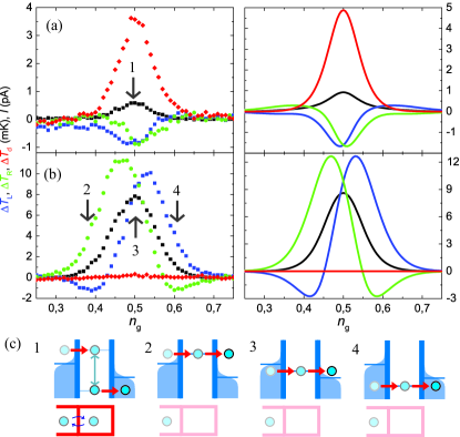
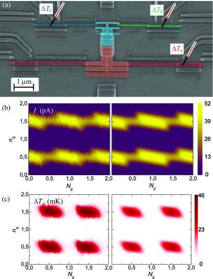
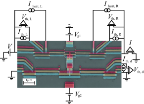
Figure 2 (a) shows a scanning electron micrograph of the experimental realization of the Maxwell’s demon. It was fabricated by standard electron beam lithography combined with shadow evaporation Dolan (1977) of copper (normal metal) and aluminum (superconductor) metal films. Our device has the following parameters: K, mK, mK, k, and k (two parallel junctions each with k tunneling resistance). The fully normal System and Demon junctions are realized with laterally proximized aluminum dot technique Koski et al. (2011). We determine the heat generated in the left (L) and right (R) lead of the System as well as the lead of the Demon by measuring the respective temperatures , , and , as indicated in Fig. 2 (a). This is achieved by reading the voltage of current-biased normal metal - insulator - superconductor junctions, see e.g. Ref. Nahum et al. (1994). Finally, the leads of the System and the Demon are interrupted with direct contacts to superconducting leads, which permit charge transport by Andreev processes Andreev (1964) but block heat transport at low temperatures. The structure is measured in a 3He / 4He dilution refrigerator at the bath temperature of 40 mK. Details on the device fabrication and measurement configuration are given in the Supplementary Material.
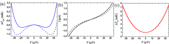
The continuous heat generation is mediated primarily by lattice phonons that couple with the conduction electron heat bath at temperature , contributing , , or , where is a material specific constant, is the volume of the circuit element, and is the base temperature Wellstood et al. (1994). For the left and right electrodes of the System, m 70 nm 20 nm. Its island is approximately twice as large in volume. The Demon has the total volume m 150 nm 20 nm. We use Wm-3K-5 for Cu. The rate of electron tunneling ( Hz) in our device is faster than the phonon relaxation rate ( Hz), however it is small compared to the inelastic electron-electron relaxation rate, which is typically of the order of Hz Pothier et al. (1997), allowing the electrodes to equilibriate to an effective electron temperature that deviates from . Furthermore, the temperature change caused by an individual tunneling electron is sufficiently small so that is a good approximation for the entropy change. The temperature equilibrates such that the net heat generation is zero, i.e. . The base temperature is measured at , where the state is Coulomb blockaded to corresponding to the energy minimum in Eq. (1) and no heat is generated in the circuit. Figure 2 (b) shows that charge current in the System modulates with as in a standard SET. However, when , the maximum measured current is reduced due to the feedback by the Demon. Figure 2 (c) demonstrates how at , the heat generated in the Demon is maximized for extracting information of the transported electrons.
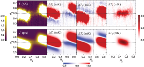
The main result of this paper is presented in Figure 3 (a), showing our observation at V of how the System cools down and its entropy decreases. Simultaneously, we observe how the Demon, which collects the information and immediately applies a feedback to the System, generates heat as a necessary thermodynamic cost for extracting information from the System. On the other hand, Figure 3 (b) shows unchanged at since the Demon is effectively uncoupled from the System as its state is locked to . With that Coulomb blockade refrigeration Pekola et al. (2014); Feshchenko et al. (2014) occurs when deviates from by causing either the left or right lead to cool down, but overall heat is generated and entropy is produced in the System.
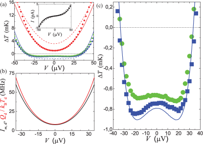
Figure 4 (a) shows a measurement of current (inset) and temperatures as a function of at . Increasing voltage bias boosts electrons to pass through the System, however, at the cost of lower entropy decrease per electron. Furthermore, the risk of electrons to pass through the System without feedback control from the Demon increases, in particular via multi-electron tunneling (see Supplementary material for details). Figure 4 (b) compares the heat and mutual information produced by the Demon, demonstrating that they differ by less than for low . The data shown in Fig. 4 (c) shows improvement of entropy decrease to up to V, beyond which errors in the feedback process overcome the benefit of enhanced rate of electron injection. At this voltage, the cooling power on the System is estimated to be aW, while the heat dissipation in the Demon is aW. Based on the heat generation, the mutual information production rate by the Demon is then Hz. The current is fA, i.e. electrons cross the System per second. Should successful feedback be performed for every electron, the heat extracted by the Demon would be aW. Experimentally we extract 52, of this value i.e. this fraction of the electrons transported through the System are successfully feedback-controlled by the Demon. For efficiency at maximal cooling power, , we the get 0.56.
In conclusion, we have realized and demonstrated experimentally a physically transparent autonomous Maxwell’s Demon on a chip, based on coupled single-electron circuits undergoing tunneling events in a self-controlled manner. The Demon acts on the System to decrease its entropy, observed as a temperature drop. The configuration allows one to measure the effect of the Demon on the System, as well as to measure the thermodynamics of the Demon itself. The device presented here demonstrates how information is transferred from the System to the Demon, leading to heat generation in the Demon in amount that corresponds to the rate of information transfer. This setup constitutes a step towards autonomous information-powered nanodevices.
We thank Matthias Meschke, Felix Ritort, and Rafael Sánchez for useful discussions. We acknowledge financial support from the Academy of Finland grants nos. 272219 and 284594, the European Union Seventh Framework Programme INFERNOS (FP7/2007-2013) under grant agreement no. 308850, and the Väisälä Foundation. We acknowledge the availability of the facilities and technical support by Otaniemi research infrastructure for Micro and Nanotechnologies (OtaNano).
References
- Leff and Rex (2003) H. S. Leff and A. F. Rex, eds., Maxwell’s Demon (IOP Publishing, Bristol, 2003).
- Szilard (1929) L. Szilard, Z. Phys. 53, 840 (1929).
- Landauer (1961) R. Landauer, IBM J. Res. Develop. 5, 183 (1961).
- Landauer (1988) R. Landauer, Nature 335, 779 (1988).
- Sagawa and Ueda (2008) T. Sagawa and M. Ueda, Phys. Rev. Lett. 100, 080403 (2008).
- Sagawa and Ueda (2010) T. Sagawa and M. Ueda, Phys. Rev. Lett. 104, 090602 (2010).
- Mandal and Jarzynski (2012) D. Mandal and C. Jarzynski, Proc. Nat. Acad. Sci. 109, 11641 (2012).
- Esposito and Schaller (2012) M. Esposito and G. Schaller, EPL (Europhysics Letters) 99, 30003 (2012).
- Deffner and Jarzynski (2013) S. Deffner and C. Jarzynski, Phys. Rev. X 3, 041003 (2013).
- Strasberg et al. (2014) P. Strasberg, G. Schaller, T. Brandes, and C. Jarzynski, Phys. Rev. E 90, 062107 (2014).
- Barato and Seifert (2014) A. C. Barato and U. Seifert, Phys. Rev. Lett. 112, 090601 (2014).
- Lutz and Ciliberto (2015) E. Lutz and S. Ciliberto, Physics Today 68, 30 (2015).
- Serreli et al. (2006) V. Serreli, C.-F. Lee, E. R. Kay, and D. A. Leigh, Nature 445, 523 (2006).
- Price et al. (2008) G. N. Price, S. T. Bannerman, K. Viering, E. Narevicius, and M. G. Raizen, Phys. Rev. Lett. 100, 093004 (2008).
- Thorn et al. (2008) J. J. Thorn, E. A. Schoene, T. Li, and D. A. Steck, Phys. Rev. Lett. 100, 240407 (2008).
- Raizen (2009) M. G. Raizen, Science 324, 1403 (2009).
- Toyabe et al. (2010) S. Toyabe, T. Sagawa, M. Ueda, E. Muneyuki, and M. Sano, Nature Phys. 6, 988 (2010).
- Bérut et al. (2011) A. Bérut, A. Arakelyan, A. Petrosyan, S. Ciliberto, R. Dillenschneider, and E. Lutz, Nature 483, 187 (2011).
- Roldán et al. (2014) E. Roldán, I. A. Martínez, J. M. R. Parrondo, and D. Petrov, Nature Phys. 10, 457 (2014).
- Koski et al. (2014a) J. V. Koski, V. F. Maisi, J. P. Pekola, and D. V. Averin, Proc. Nat. Acad. Sci. 111, 13786 (2014a).
- Koski et al. (2014b) J. V. Koski, V. F. Maisi, T. Sagawa, and J. P. Pekola, Phys. Rev. Lett. 113, 030601 (2014b).
- Parrondo et al. (2015) J. M. R. Parrondo, J. M. Horowitz, and T. Sagawa, Nature Phys. 11, 131 (2015).
- Chida et al. (2015) K. Chida, K. Nishiguchi, G. Yamahata, H. Tanaka, and A. Fujiwara, Appl. Phys. Lett. 107, 073110 (2015).
- Barato and Seifert (2013) A. C. Barato and U. Seifert, Europhys. Lett. 101, 60001 (2013).
- Strasberg et al. (2013) P. Strasberg, G. Schaller, T. Brandes, and M. Esposito, Phys. Rev. Lett. 110, 040601 (2013).
- Shirashi et al. (2015) N. Shirashi, S. Ito, K. Kawaguchi, and T. Sagawa, New J. Phys. 17, 045012 (2015).
- Averin and Likharev (1986) D. V. Averin and K. K. Likharev, J. Low Temp. Phys. 61, 345 (1986).
- Sánchez and Büttiker (2012) R. Sánchez and M. Büttiker, Europhys. Lett. 100, 47008 (2012).
- Zhang et al. (2015) Y. Zhang, G. Lin, and J. Chen, Phys. Rev. E 91, 052118 (2015).
- Solomon et al. (1989) P. M. Solomon, P. J. Price, D. J. Frank, and D. C. La Tulipe, Phys. Rev. Lett. 63, 2508 (1989).
- Averin et al. (1991) D. V. Averin, A. N. Korotkov, and Yu. V. Nazarov, Phys. Rev. Lett. 66, 2818 (1991).
- Abreu and Seifert (2012) D. Abreu and U. Seifert, Phys. Rev. Lett. 108, 030601 (2012).
- Horowitz and Esposito (2014) J. M. Horowitz and M. Esposito, Phys. Rev. X 4, 031015 (2014).
- Pekola et al. (2014) J. P. Pekola, J. V. Koski, and D. V. Averin, Phys. Rev. B 89, 081309(R) (2014).
- Feshchenko et al. (2014) A. V. Feshchenko, J. V. Koski, and J. P. Pekola, Phys. Rev. B 90, 201407(R) (2014).
- Dolan (1977) G. J. Dolan, Appl. Phys. Lett. 31, 337 (1977).
- Koski et al. (2011) J. V. Koski, J. T. Peltonen, M. Meschke, and J. P. Pekola, Appl. Phys. Lett. 98, 203501 (2011).
- Nahum et al. (1994) M. Nahum, T. M. Eiles, and J. M. Martinis, Appl. Phys. Lett. 65, 3123 (1994).
- Andreev (1964) A. F. Andreev, JETP 19, 1228 (1964).
- Wellstood et al. (1994) F. C. Wellstood, C. Urbina, and J. Clarke, Phys. Rev. B 49, 5942 (1994).
- Pothier et al. (1997) H. Pothier, S. Guéron, N. O. Birge, D. Esteve, and M. H. Devoret, Phys. Rev. Lett. 79, 3490 (1997).
Supplementary Material
Fabrication and measurement setup:
The System and Demon were formed simultaneously in four steps. First, a 15 nm Al (superconductor, S) layer was evaporated to form the bottommost shadow, see Fig. S1. This was directly followed by an evaporation of 20 nm Cu (normal metal, N) layer to form the middle shadow. Any metal-to-metal contacts between Al and Cu are transparent NS contacts. After the second evaporation, the sample was exposed to oxygen, forming a thin AlxOy layer on any Al not already covered by Cu. Finally, a second 20 nm layer of Cu was evaporated as the topmost shadow. Most of the contacts formed between Al and Cu at the third evaporation are NIS tunnel junctions with the AlxOy as the insulator (I). However, small Al dots with a direct contact to Cu are rendered normal due to inverse proximity effect Koski et al. (2011). This technique is used to form the NIN junctions for the System and the Demon. Copper oxidizes significantly slower than Al, thus any Cu-Cu contacts are practically transparent. The capacitive coupling between the islands of the SET and the Demon was achieved with parallel plate capacitance to an underlying Au strip evaporated prior to the SET - detector structure, covered with nm of AlxOy achieved by atomic layer deposition (ALD). As the NIS junctions are operated as thermometers, they simultaneously induce some cooling Nahum et al. (1994) on the electrodes probed. To initialize the System in such a way that and are at the same temperature as the island, the System leads are equipped with additional current-biased tunnel junctions that induce heating to compensate for this NIS cooling effect.
Tunneling and heat generation rates
This section gives the equations for the tunneling rates through the junctions in this device. Tunneling events may take place through the left or right System junction both with a resistance k, or through the left or right Demon junction both with resistance k. However, as the Demon is not voltage biased, the two junctions are parallel junctions to the same potential, and can thus can be modeled as a single one with k. A tunneling event may take place between the left System lead (L) or right System lead (R) and the System island (I) at rate
| (6) |
where is the energy cost for the tunneling electron, L, R, and is the Fermi-Dirac distribution of the conduction electrons in the metal L, R, I. Similarly, the tunneling rate between the Demon lead (d) and its island (D) is
| (7) |
We assume that , in which case Eq. (7) simplifies to . Moreover, if the System is at uniform temperature implying , the System tunneling rate simplifies to .
Next follow the equations for the rates of heat generation. Heat generation rate in the metal L, R by electrons tunneling between and I is , and in I it is . With , these simplify to , where is the total rate of heat generation on the System, summing over the rates of the lead and the island between which the tunneling takes place. It also satisfies
| (8) |
Finally, the heat generation rate by electron tunneling in the Demon (summing over d and D, with ) is .
We note that the equations above only depend on the energy cost for the tunneling process. It depends on the initial state and source and destination of the electron, as
| (9) |
Full expressions for and
Although the states and are dominant, we also consider higher energy states in the simulations. A master equation for the configuration at steady state is written as
| (10) |
which can be solved from Eq. (10) by noting . In the steady state, the current through the System is the same in each cross-section and can then be written as . The rate of heat generation in the metal L, R is , and in I it is , and finally in the Demon it is . The simplified forms written in Eqs. (2, 3) in the main text are obtained in the two-by-two-state limit at , with uniform temperatures and , , using Eq. (8).
The final temperatures are determined by solving the heat balance equation for each circuit element, indexed by = L, R, I, or d, as . The term is otherwise zero but for the metal L, R, it is the heat leak through the heater junctions by Wiedemann-Franz law, WK-2 is the Lorenz number, is the electrode temperature, is the base temperature of that electrode, and M is the resistance of the heater junctions.
Temperature threshold for cooling
In this section we derive the threshold temperature for the Demon to be able to cool down the System. We consider and uniform temperatures for the System and for the Demon. In the main text Eq. (2), the rate of heat generation in the System is
| (11) |
where . With notation , , and , the second derivative of Eq. (11) is
| (12) |
If we further have , we can write and Eq. (12) reduces to
| (13) |
The critical threshold to achieve cooling is , i.e. in which case for a finite we can achieve negative . In the limit , the numerically obtained threshold is .
Multi-electron tunneling
Tunneling beyond single-electron processes is considered in the same way as in Ref. Pekola et al. (2014). In particular, we consider the multi-electron tunneling for the data in Fig. 4 of the manuscript, where . When and (or and ), any single electron tunneling event costs energy. For example, a tunneling event in the System from source to the island would bring from 0 to 1 with an energy cost . However, if another electron would afterwards tunnel in the Demon, bringing from 1 to 0, that electron would gain in energy, resulting in a total energy gain . Furthermore, in our experiment the k is close to the resistance quantum, k, giving rise to multi-electron tunneling in scenarios, where single electron tunneling costs energy whereas with multiple tunneling events the total energy cost would be negative. Consider an electron tunneling event with an energy cost . Right after the event, there are six possible follow-up transitions (indexed ), 1: , 2: , 3: , 4: , 5: d D, or 6: D d, each with its respective energy cost (see Eq. (9)). In this context, the equations for calculating rates of tunneling and heat induced are modified by energy broadening , where the tunneling rate of the transition (see Eqs. (6, 7)). The rate of heat generation is modified as
| (14) |
where the subscripts and superscripts are the same for and on the left and right hand side of the equation (for example, to solve , one would insert to the right-hand side). Similarly, the modified tunneling rates are given by . The rates evaluated by the this expression are used in Eq. (10) to evaluate the probability distribution . Energy conservation demands that the total rate of heat generation induced by the tunneling processes satisfies . In addition to the heat generation of Eq. (14), each junction dissipates energy as heat at a rate proportional to . Thus the additional rate of heat generated by the virtual processes for each junction (including the junction where the actual tunneling event occurs) is , approximately to split evenly between the electrodes shared by the junction. Now , where ’from’ and ’to’ refer to the source and destination of the tunneling electron, satisfies energy conservation. Finally, we note that in the limit of with s, d, the effect of multi-electron tunneling should vanish: indeed with , and , whereas .
In addition to energy broadening, we consider direct co-tunneling processes, where two electrons tunnel simultaneously. The first tunneling event takes place between pair (L,I), (R,I), or (d,D), which we indicate with A, and the second tunneling event takes place over another pair, indicated with B. The energy cost for the events are and , respectively, in the case only that event took place. If both tunneling events take place, the total energy cost is . When , cotunneling events become relevant. The rate of co-tunneling is and the heat dissipation rate in A is , where the superscript for is the same for left and right hand side of the equation (see the similar discussion after Eq. (14)). The heat dissipation rate in junction B is . Figure S2 shows the effect of multi-electron tunneling in contrast to what would be expected if only single-electron tunneling would take place. Additional current leaks through the System without the feedback from the Demon, resulting in smaller cooling power on the System.
Gate dependence of temperatures
Figure S3 shows how our configuration behaves as a function of and . Figure 3 in the main text has been obtained from these type of measurements.
Discussion on demon memory
Many theoretical works on autonomous Maxwell’s demons Mandal and Jarzynski (2012); Esposito and Schaller (2012); Deffner and Jarzynski (2013); Barato and Seifert (2014); Strasberg et al. (2014) consider systems in contact with ”information reservoirs”, represented by sequence of bits in the models. In these models the information reservoirs exchange no energy with the system.
The relation between our setup and these models can be understood by considering the two-level demon state as a memory (one bit). In the other works the sequence of bits has been initialized to a preferred initial state. That is to say, the system has been subjected to a pre-determined stream of bits. In our setup the sequence of bits is prepared by the demon itself while it operates, and not given by initialization of the stream. Because the demon has to erase the single-bit memory for the next feedback operation, there is a thermodynamic cost for this erasure, which is seen as dissipation of heat in the setup.
As the authors in Ref. Barato and Seifert (2014) point out, it is possible to study the entropic interactions between the system and the information reservoir using entropic currents, which is presented by the flow of mutual information in our model. In the works Esposito and Schaller (2012); Strasberg et al. (2014), the authors show in detail that in fact the entropy production and the dynamics can be understood either by considering the flow of mutual information or the model of information resource with entropy difference in the incoming and outcoming bit streams (entropy difference in the information resource).
The change in the demon state (flipping of a bit) changes the energy barriers between the system states. At this stage, the system does not yet experience transitions and therefore does not cool down, thus there is no energy transfer between the system and the demon. The carriers of heat in the setup are the electrons, and no electrons can tunnel between the system and the demon, such that direct heat exchange is in fact impossible in our setup.
References
- Leff and Rex (2003) H. S. Leff and A. F. Rex, eds., Maxwell’s Demon (IOP Publishing, Bristol, 2003).
- Szilard (1929) L. Szilard, Z. Phys. 53, 840 (1929).
- Landauer (1961) R. Landauer, IBM J. Res. Develop. 5, 183 (1961).
- Landauer (1988) R. Landauer, Nature 335, 779 (1988).
- Sagawa and Ueda (2008) T. Sagawa and M. Ueda, Phys. Rev. Lett. 100, 080403 (2008).
- Sagawa and Ueda (2010) T. Sagawa and M. Ueda, Phys. Rev. Lett. 104, 090602 (2010).
- Mandal and Jarzynski (2012) D. Mandal and C. Jarzynski, Proc. Nat. Acad. Sci. 109, 11641 (2012).
- Esposito and Schaller (2012) M. Esposito and G. Schaller, EPL (Europhysics Letters) 99, 30003 (2012).
- Deffner and Jarzynski (2013) S. Deffner and C. Jarzynski, Phys. Rev. X 3, 041003 (2013).
- Strasberg et al. (2014) P. Strasberg, G. Schaller, T. Brandes, and C. Jarzynski, Phys. Rev. E 90, 062107 (2014).
- Barato and Seifert (2014) A. C. Barato and U. Seifert, Phys. Rev. Lett. 112, 090601 (2014).
- Lutz and Ciliberto (2015) E. Lutz and S. Ciliberto, Physics Today 68, 30 (2015).
- Serreli et al. (2006) V. Serreli, C.-F. Lee, E. R. Kay, and D. A. Leigh, Nature 445, 523 (2006).
- Price et al. (2008) G. N. Price, S. T. Bannerman, K. Viering, E. Narevicius, and M. G. Raizen, Phys. Rev. Lett. 100, 093004 (2008).
- Thorn et al. (2008) J. J. Thorn, E. A. Schoene, T. Li, and D. A. Steck, Phys. Rev. Lett. 100, 240407 (2008).
- Raizen (2009) M. G. Raizen, Science 324, 1403 (2009).
- Toyabe et al. (2010) S. Toyabe, T. Sagawa, M. Ueda, E. Muneyuki, and M. Sano, Nature Phys. 6, 988 (2010).
- Bérut et al. (2011) A. Bérut, A. Arakelyan, A. Petrosyan, S. Ciliberto, R. Dillenschneider, and E. Lutz, Nature 483, 187 (2011).
- Roldán et al. (2014) E. Roldán, I. A. Martínez, J. M. R. Parrondo, and D. Petrov, Nature Phys. 10, 457 (2014).
- Koski et al. (2014a) J. V. Koski, V. F. Maisi, J. P. Pekola, and D. V. Averin, Proc. Nat. Acad. Sci. 111, 13786 (2014a).
- Koski et al. (2014b) J. V. Koski, V. F. Maisi, T. Sagawa, and J. P. Pekola, Phys. Rev. Lett. 113, 030601 (2014b).
- Parrondo et al. (2015) J. M. R. Parrondo, J. M. Horowitz, and T. Sagawa, Nature Phys. 11, 131 (2015).
- Chida et al. (2015) K. Chida, K. Nishiguchi, G. Yamahata, H. Tanaka, and A. Fujiwara, Appl. Phys. Lett. 107, 073110 (2015).
- Barato and Seifert (2013) A. C. Barato and U. Seifert, Europhys. Lett. 101, 60001 (2013).
- Strasberg et al. (2013) P. Strasberg, G. Schaller, T. Brandes, and M. Esposito, Phys. Rev. Lett. 110, 040601 (2013).
- Shirashi et al. (2015) N. Shirashi, S. Ito, K. Kawaguchi, and T. Sagawa, New J. Phys. 17, 045012 (2015).
- Averin and Likharev (1986) D. V. Averin and K. K. Likharev, J. Low Temp. Phys. 61, 345 (1986).
- Sánchez and Büttiker (2012) R. Sánchez and M. Büttiker, Europhys. Lett. 100, 47008 (2012).
- Zhang et al. (2015) Y. Zhang, G. Lin, and J. Chen, Phys. Rev. E 91, 052118 (2015).
- Solomon et al. (1989) P. M. Solomon, P. J. Price, D. J. Frank, and D. C. La Tulipe, Phys. Rev. Lett. 63, 2508 (1989).
- Averin et al. (1991) D. V. Averin, A. N. Korotkov, and Yu. V. Nazarov, Phys. Rev. Lett. 66, 2818 (1991).
- Abreu and Seifert (2012) D. Abreu and U. Seifert, Phys. Rev. Lett. 108, 030601 (2012).
- Horowitz and Esposito (2014) J. M. Horowitz and M. Esposito, Phys. Rev. X 4, 031015 (2014).
- Pekola et al. (2014) J. P. Pekola, J. V. Koski, and D. V. Averin, Phys. Rev. B 89, 081309(R) (2014).
- Feshchenko et al. (2014) A. V. Feshchenko, J. V. Koski, and J. P. Pekola, Phys. Rev. B 90, 201407(R) (2014).
- Dolan (1977) G. J. Dolan, Appl. Phys. Lett. 31, 337 (1977).
- Koski et al. (2011) J. V. Koski, J. T. Peltonen, M. Meschke, and J. P. Pekola, Appl. Phys. Lett. 98, 203501 (2011).
- Nahum et al. (1994) M. Nahum, T. M. Eiles, and J. M. Martinis, Appl. Phys. Lett. 65, 3123 (1994).
- Andreev (1964) A. F. Andreev, JETP 19, 1228 (1964).
- Wellstood et al. (1994) F. C. Wellstood, C. Urbina, and J. Clarke, Phys. Rev. B 49, 5942 (1994).
- Pothier et al. (1997) H. Pothier, S. Guéron, N. O. Birge, D. Esteve, and M. H. Devoret, Phys. Rev. Lett. 79, 3490 (1997).