Stabilization of highly polar BiFeO3-like structure: a new interface design route for enhanced ferroelectricity in artificial perovskite superlattices
Abstract
In ABO3 perovskites, oxygen octahedron rotations are common structural distortions that can promote large ferroelectricity in BiFeO3 with an structure NeatonBFO , but suppress ferroelectricity in CaTiO3 with a symmetry Benedek_JPCC . For many CaTiO3-like perovskites, the BiFeO3 structure is a metastable phase. Here, we report the stabilization of the highly-polar BiFeO3-like phase of CaTiO3 in a BaTiO3/CaTiO3 superlattice grown on a SrTiO3 substrate. The stabilization is realized by a reconstruction of oxygen octahedron rotations at the interface from the pattern of nonpolar bulk CaTiO3 to a different pattern that is characteristic of a BiFeO3 phase. The reconstruction is interpreted through a combination of amplitude-contrast sub high-resolution transmission electron microscopy and first-principles theories of the structure, energetics, and polarization of the superlattice and its constituents. We further predict a number of new artificial ferroelectric materials demonstrating that nonpolar perovskites can be turned into ferroelectrics via this interface mechanism. Therefore, a large number of perovskites with the CaTiO3 structure type, which include many magnetic representatives, are now good candidates as novel highly-polar multiferroic materials Physics_Today .
I Introduction
New mechanisms to generate ferroelectricity (FE) have recently been the subject of active research, due to both fundamental interest and the technological importance of ferroelectrics and related materials Dawber_Review . Novel ferroelectrics have potentially higher performance for practical applications, as well as potential compatibility with other functional properties such as magnetism, yielding multiferroics and other multifunctional materials Physics_Today ; Schlom_Nature_2010 ; Benedek_hybrid_improper .
Artificially structured perovskite superlattices offer rich opportunities for novel ferroelectricity Rabe_Science ; Lee_Nature_tricolor ; Warusawithana_tricolor_PRL ; Sai_PRL_2000 ; Bousquet_Nature . Non-bulk phases for the constituent layers can be stabilized by the mechanical and electrical boundary conditions characteristic of a superlattice Rabe_Review_2007 ; Stengel_Nature_Physics , potentially turning constituents that are nonpolar in bulk form into ferroelectrics Neaton_2003 ; Eom_STO_2010 . Competing low-energy metastable phases can be readily found in perovskites with low tolerance factors, promoting oxygen octahedron rotation (OOR) instabilities along the Brillouin-zone-boundary R-M line. The ground state structure in such cases is generally the nonpolar orthorhombic structure. As a typical example, the oxygen octahedron in a CaTiO3 (CTO) can be described by its rotation around [110] axis and an in-phase rotation around [001] axis (a-a-c+ in Glazer notation). Such a pattern of OOR favors antipolar behavior instead of FE Benedek_JPCC . On the other hand, OOR with a different pattern can also promote large FE. As one famous example, in BiFeO3 (BFO) with structure, the oxygen octahedron can be characterized by a rotation around [110] and an out-of-phase rotation around [001], yielding a fairly large polarization along [111] (a-a-a- in Glazer notation). Compared to the widespread of CTO-like materials, BFO-like perovskites are relatively rarely seen. As a result, the OOR is generally thought to suppress FE in perovskites.
However, for many perovskites, the BFO-like structure serves as a low-energy metastable phase Benedek_JPCC . Therefore, it would be beneficial if an artificial perovskite superlattice could stabilize this metastable phase for the entire constituent layers or in a region near interface. To this end, a reliable design mechanism can be derived only from precisely determined atomic positions in experiments followed by theoretical interpretations based on first-principles calculations.
II Experimental and first-principles results
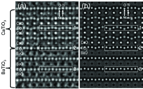
Aberration-corrected high-resolution transmission electron microscopy (HRTEM) is a powerful method for accurate visualization of oxygen octahedron distortions Jia_TEM_2003 ; Jia_TEM_2008 . Recently, it was shown that amplitude contrast imaging in HRTEM could be used to discriminate heavy and light element columns based on channeling contrast ACI , allowing one to locate the exact interface and to visualize OOR angles in different atomic layers (see Supplementary Materials S1). Fig. 1(a) shows an experimental HRTEM image of a 4BaTiO3(BTO)/4CTO superlattice film along the [110] direction of the SrTiO3 (STO) substrate. This image was obtained by correcting both spherical and chromatic aberrations to achieve amplitude contrast imaging conditions (Cs = 3 , Cc = ). In this image, channeling contrast between Ca and Ba columns is clearly observed: atomic columns of CaO and BaO appear as bright and dark dots, respectively; oxygen and Ti columns appear as bright dots. Due to the interdiffusion of Ba and Ca at the interface, the intensity at A site varies depending on the ratio of Ca and Ba as discussed in detail in the supplementary material (S2). It is seen that BTO and CTO grow coherently on the STO substrate, showing the same in-plane lattice constant as that of STO, and elongated c-axis in the BTO layer and shortened c-axis in the CTO layer (see Supplementary Materials S3). Within the CTO layer of the superlattice (box 1), a strongly corrugated TiO2 plane is observed in which the oxygen atoms displace upward and downward with respect to the central Ti atoms, corresponding to an OOR around [110] by 9∘, comparable to that of bulk CTO. For TiO2 planes between two BaO planes (box 3), alternating displacement of the oxygen atoms, and thus the amplitude of the OOR, is negligible, consistent with the fact that bulk BTO strongly resists OORs. For TiO2 planes between one BaO and one CaO plane (box 2), the OOR around [110] is 3∘, smaller than that in the interior of the CTO layers.
For comparison, in Fig. 1(b) we present the simulated HRTEM image using the atomic positions of the 4BTO/4CTO superlattice obtained from first-principles calculations. The simulated HRTEM image for the computed structure shows the same pattern of OOR as in the experiment (compare boxes 1, 2, and 3 in Fig. 1(a) and (b)), with amplitudes of 12.5∘ in the CTO layer and 5.5∘ at the interface. The quantitative difference in OOR around [110] angles from the experimental observation can be partly attributed to the fact that the experiments were performed at T= 300 K, while the ground state structural relaxation by density functional theory was at T = 0 K. In addition, in this image it is possible to discern the small uniform displacement of the oxygens relative to the Ti atoms in the TiO2 plane, which is associated with the spontaneous polarization of the superlattice. While this displacement is present in all the TiO2 layers, it can be more easily identified in those belonging to the interior BTO layers, which do not have the corrugation associated with OOR.
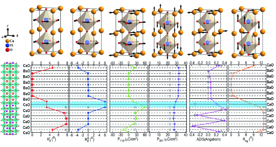
We use the atomic-scale information from the first-principles results for a detailed layer-by-layer investigation of the properties of the superlattice. We focus our discussion on the 6BTO/6CTO superlattice, which allows a clearer distinction between the interface and interior layers; the corresponding results for the 4BTO/4CTO superlattice are similar (see Supplementary Materials S6). The computed spontaneous polarization is 29 along [001] and 11 along [110]. The resulting layer-by-layer decomposed structural distortions and polarizations are shown in Fig. 2.
| Boundary | Fixed field | Fixed field | |||
|---|---|---|---|---|---|
| Condition | |||||
| Perovskite | BaTiO3 | CaTiO3 | CaTiO3 | CaTiO3 | CaTiO3 |
| Symmetry | P4mm | Pbnm | e-R3c | Pbnm | e-R3c |
| R | 0 | 7.7 | 0 | 7.6 | 0 |
| R | 0 | 0 | 7.3 | 0 | 7.2 |
| Rxy | 0 | 12.7 | 11.5 | 12.8 | 11.7 |
| ADIS | 0 | 0.29 | 0 | 0.32 | 0 |
| 41.93 | 0 | 20.01 | 27.81 | 28.96 | |
| 0 | 26.40 | 52.19 | 24.53 | 51.25 | |
| 41.93 | 26.40 | 55.89 | 37.08 | 58.87 | |
| 1.067 | 0.964 | 0.968 | 0.965 | 0.967 | |
| Energy | -162.645 | -164.158 | -164.066 | -164.106 | -164.040 |
According to the dielectric slab model Neaton_2003 , the structure of the constituent layers of the superlattice should be closely related to those of strained bulk materials under the electrical boundary condition of a fixed displacement () field, imposed by the superlattice as summarized in Table 1. Indeed, as shown in Fig. 2, the interior BTO layers have negligible OOR with a polarization of 32 along the [001] direction. This is consistent with the structure and large polarization of strained BTO; the reduction from the strained bulk value of 42 can be attributed to the electrostatic cost of polarizing the nonpolar CTO layer. Both bulk CTO and strained bulk CTO are characterized by the strong OORs due to structural instabilities at the zone-boundary and points. Therefore, the interior CTO layers are dominated by and , which are OOR around [110] and an in-phase OOR around [001] respectively as shown in Fig. 2. In addition, a large antipolar (AFE) mode develops in the CTO layers that can be clearly identified by the zig-zag movement of A-site displacement along [110] direction. It should be stressed that this antipolar distortion is a structural distortion at the point favored by the trilinear coupling due to the pattern of OOR in CTO-like materials. The above distortion in the interior CTO layers can be clearly seen in Fig. 2, as well as in the TEM image in Fig. 1 (a) (see Supplementary Materials S5). This AFE mode was also recently pointed out to be the key to the suppressed FE in all CTO-like perovskites Benedek_JPCC . Due to the applied tensile epitaxial strain, the interior CTO layers are polar along [110] direction with a magnitude of just like the strained CTO Eklundpaper2009 .
If the interface effect is negligible, the dielectric slab model can be used to predict the polarization, yielding a value of along the [001] direction. The first-principles calculation gives . The discrepancy from the dielectric slab model suggests that the interface effect cannot be neglected. Such a large enhancement of the polarization () is a strong indication of a highly polar interface reconstruction. Indeed, examination of Fig. 2 reveals that the structure at the interface of the CTO layers differs significantly from that of the strained bulk CTO, with the OOR being suppressed at the interface of the superlattice. The AFE type displacement, which is driven by the trilinear coupling Benedek_JPCC involving the OORs of CTO, is suppressed too. Furthermore, a new structural pattern of OOR emerges at the interface: an OOR around the [110] axis and an out-of-phase OOR around the [001] axis for a TiO6 sandwiched between two interface CaO layers, with rotation angles comparable to those of the strained bulk in-phase OOR. This new structure pattern is exactly the same as one would observe for oxygen octahedron rotation in BiFeO3 and similar perovskites with symmetry.
III Microscopic mechanism
Here, we propose that this change in structure at the interface can be interpreted as the local stabilization of a BFO-like structure different from that of the bulk CTO. As far as the topology of the oxygen octahedron rotation network is concerned, oxygen octahedra in both BFO and CTO rotate around [110]; however, BFO differentiates itself from CTO by its out-of-phase OOR around [001] instead of the in-phase counterpart in CTO. The out-of-phase and in-phase OOR around [001] originate from symmetry-nonequivalent structural instabilities at the and points respectively. This stabilization of a BFO-like structure in CTO layers near the interface is derived from the metastable polar e- phase and is compatible with a much larger polarization than that in bulk CTO as shown in Table 1. It has been shown that this phase cannot be stabilized relative to the phase by epitaxial strain alone Eklund_Thesis . However, in the superlattice, the suppression of the tilt angles by proximity to BTO, assisted by the electrical and mechanical boundary conditions that favor a phase with a component of polarization along [001], is sufficient to stabilize the structure Zhou_Thesis .
To explore the stabilization of this phase more quantitatively, we constructed first-principles based models for the strained phase (designated ) and for the metastable e- phase (). Facilitated by space group symmetry analysis, the models of both and are built through polynomial expansions of the total energy from first-principles calculations with respect to the high-symmetry reference structure ( phase) in terms of the amplitudes of the relevant modes. In the above, , , , , , represent the mode amplitude of in-phase OOR around [001], out-of-phase OOR around [001], OOR around [110], in-plane antipolar mode and in-plane and out-of-plane FE modes respectively. The resulting models are shown in the following for and respectively as (see Supplementary Materials S7 for fitted coefficients):
| (1) |
| (2) |
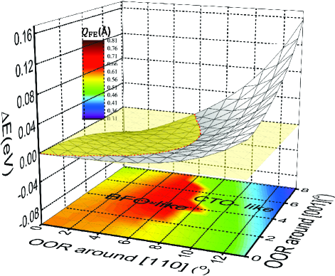
Assuming the angles of the oxygen octahedron rotations are tunable parameters under experimental conditions, we further define the functions , and . In order to understand how the BFO-like phase can be stabilized relative to the CTO-like phase, we then evaluate as functions of oxygen octahedron rotation magnitudes around [110] and [001]. The resulting is presented in Fig. 3. The total FE mode amplitudes are also presented by the color spectrum in the base plane in Fig. 3. It can be seen that when the angles are fixed to the values of bulk CTO regions in the superlattice, as shown in Fig. 2 ( and ), the CTO-like phase is strongly favored in energy. In the CTO-like phase, as shown in Fig. 2 and Table 1, the antipolar distortion is favored over the FE distortion due to the large trilinear coupling term in Eq. 1. Notably, when the amplitudes of OORs are reduced, the BFO-like phase becomes energetically more stable than the CTO-like phase as shown in Fig. 3. This indicates that the BFO-like phase can be stabilized over the CTO-like phase when the OOR is reduced. When the above transition takes place, the OOR around [001] will change abruptly from in-phase rotation to out-of-phase rotation signifying a more drastic change in the topology of the oxygen octahedron network, as guided by the yellow plane at in Fig. 3. In addition to the pattern change of OOR, the BFO-like phase is generally found to have much larger polarization than that in the CTO-like phase as shown by the color spectrum in Fig. 3. The much stronger FE polarization is expected, originating from the e- phase; it can also be easily understood by the large four-linear coupling term , which promotes FE in both the in-plane and out-of-plane directions.
This mechanism leads to the BFO-like phase that exists at the interface of the BTO/CTO superlattice. Assuming the octahedra to be fairly rigid, the reduction of OOT is imposed by the adjoining BTO layer, which is strongly resistant to the OOR. A direct consequence of the stabilization of the BFO-like structure at the interface is that the polarization of the superlattice is greatly enhanced. For a particular choice of angles with and similar to those at the interface of the BTO/CTO superlattice, the computed polarization of the BFO-like phase is over 54.0 , which is comparable to the polarization in the bulk e- CTO as shown in Table 1. In the superlattice, the BFO-like phase is further favored by both the electric and mechanical boundary conditions imposed by the polarization of the BTO layer according to Eq. 2. Under the continuous displacement field along [001] direction, the electric boundary condition tends to polarize the CTO components with a larger . Under the tensile strain, the mechanical boundary condition effectively enhances . The larger and tend to further lower the energy through and stabilize the BFO-like phase.
IV Inverse design of new ferroelectric materials
It has long been recognized that oxygen octahedron rotation can play different roles in perovskites promoting FE in BFO-like materials NeatonBFO ; Zeches-BFO but suppressing FE in CTO-like materials Benedek-CTO . However, the results presented here suggest that a transition between these two phases can be achieved through interface engineering in a superlattice. In addition to improving the fundamental understanding of these transitions, these results suggest a new pathway to induce FE in functional oxide materials.
| A’BO3/A”BO3 | Enh. | Sub. | ||||
|---|---|---|---|---|---|---|
| 2BaTiO3/2CaTiO3 | 41.9 | 25.7 | 25.5 | 39.9 | 56% | SrTiO3 |
| 2BaTiO3/2CdTiO3 | 50.8 | 37.8 | 34.2 | 50.4 | 47% | NdGaO3 |
| 2KNbO3/2NaNbO3 | 36.2 | 0 | 19.8 | 37.5 | 89% | DyScO3 |
| 2KNbO3/2AgNbO3 | 36.2 | 0 | 22.0 | 38.2 | 73% | DyScO3 |
The enhanced polarization observed in the BTO/CTO superlattice studied here demonstrates this mechanism. To explore the potential of this approach, we predict a few more superlattices A’B/A”B as listed in Table 2. Within this category of tailored materials, one of the parent bulk A’B is chosen to be a “CTO-like” perovskite with strong oxygen octahedron rotations, resulting in an antipolar type (CaTO3 and CdTO3) Moriwake-CdTiO or an antiferroelectric type (AgNbO3 and NaNbO3) Fu-AgNbO ; Kania-AgNbO ground state that is favored by the trilinear coupling term. The other parent bulk A”B is chosen to have a large tolerance factor resisting oxygen octahedron rotation and a strong FE polarization. Similar to what we have already shown for the BTO/CTO example, the out-of-phase OORs around [001] are induced around the interface layers of A’B (see Supplementary Materials S8 for examples of 2BaTiO3/2CaTiO3 and 2KNbO3/2AgNbO3). As a result, the overall polarizations of the superlattices are enhanced compared to the predictions from the dielectric slab model, which is equivalent to applying the charge continuity principle only and neglecting completely the possible interface reconstruction.
| A’(A”)BO3 | Mode Decompositions() | OOR Angles() | Polarization() | Enh. | Substrate | Sym. | |||||||||
| A’BO3/A”BO3 | Q | Q | Q | Q | Q | Q | R | R | Rxy | ||||||
| CdSnO3 | 0 | 1.22 | 1.85 | 0 | 0 | 0.79 | 0 | 12.0 | 17.7 | 0 | 0 | 0 | - | KTaO3 | Pnma |
| BaSnO3 | 0 | 0 | 0 | 0 | 0 | 0 | 0 | 0 | 0 | 0 | 0 | 0 | - | KTaO3 | P4/mmm |
| 1CdSnO3/1BaSnO3 | 1.08 | 0 | 1.21 | 0.20 | 0.60 | 0 | 9.4 | 0 | 12.2 | 8.9 | 13.5 | 16.2 | KTaO3 | Pc | |
| CdHfO3 | 0 | 1.27 | 1.74 | 0 | 0 | 0.69 | 0 | 12.3 | 16.9 | 0 | 0 | 0 | - | KTaO3 | Pbnm |
| BaHfO3 | 0 | 0 | 0 | 0 | 0 | 0 | 0 | 0 | 0 | 0 | 0 | 0 | - | KTaO3 | P4/mmm |
| 1CdHfO3/1BaHfO3 | 1.07 | 0 | 1.17 | 0.18 | 0.64 | 0 | 9.3 | 0 | 12.2 | 7.8 | 10.8 | 13.3 | KTaO3 | Pc | |
| CaZrO3 | 0 | 1.02 | 1.82 | 0 | 0 | 0.72 | 0 | 9.2 | 16.2 | 0 | 0 | 0 | - | MgO | Pcmn |
| BaZrO3 | 0 | 0 | 0 | 0 | 0 | 0 | 0 | 0 | 0 | 0 | 0 | 0 | - | MgO | P4/mmm |
| 1CaZrO3/1BaZrO3 | 0.79 | 0 | 1.22 | 0.27 | 0.71 | 0 | 6.6 | 0 | 10.8 | 11.1 | 27.6 | 29.7 | MgO | Pc | |
| 1CaZrO3/1BaZrO3 | 0.90 | 0 | 1.16 | 0.30 | 0.67 | 0 | 8.1 | 0 | 10.6 | 13.5 | 22.5 | 26.2 | Relaxed | Pc | |
This approach to create new FE materials by interfacial control can also be used to create new materials even where the building blocks could come only from nonpolar perovskites. In Table 3, we list a few predicted 1A’B/1A”B superlattices within this category. These interface materials also provide us a good opportunity to perform rigorous mode decompositions based on space group theory followed by a careful comparison between the interface materials and the parent bulk compounds. The resulting mode decompositions and the local properties are also shown in Table 3. The A’B is again a “CTO-like” perovskite with strong oxygen octahedron rotations. The above property is clearly represented by the large mode amplitudes of Q and Q which correspond to an OOR around [110] and in-phase OOR around [001] as shown in Table 3. Under such a pattern of OORs, the antipolar mode Q is favored, and FE is strongly suppressed resulting in zero polarization along all directions. On the other hand, A”B is a strong “cubic” perovskite Ahmed-BaZrO ; Bouhemadou-BaHfO ; Maekawa-BaSnO that does not display structural distortions associated with either OORs or polarization at its ground state as shown in Table 3.
Strikingly, when A’B and A”B form a 1A’B/1A”B superlattice, the resulting structural distortions are significantly different from their parent bulks. The differences come not only from the amplitudes of the modes but also from the symmetries associated with these modes. In Table 3, the OORs around [110] Q are preserved in all these superlattices but, with largely reduced mode amplitudes compared with those in bulk A’B. In contrast, the in-phase OOR around [001] Q completely disappears and is replaced by a large mode amplitude Q associated with an out-of-phase OOR around the same axis in all the predicted new materials. As we have seen repeatedly in the previous discussions, such a new pattern of OOR signifies the stabilization of a “BFO-like” structure in all these artificial materials. Accordingly, large polarizations develop along both [001] and [110] directions with the generated total polarization vector roughly along the [111] direction due to the broken symmetry in the e- phase. It can be noted that the polarization of BiFeO3 is exactly along [111] direction in the symmetry. At the same time, the antipolar mode Q is completely eliminated. Here, we want to stress that none of the component perovskites in the predicted superlattices is polar either in its natural bulk or in its strained bulk formats!
V Outlook
Currently, there are two widely adopted interface approaches to induce FE in oxide superlattices, namely tricolor Sai_PRL_2000 and hybrid improper methods Rondinelli . An artificially induced broken inversion symmetry lies at the heart of both the above two methods. In the former, the broken inversion symmetry along the out-of-plane direction is introduced by the number of species in the superlattice; while in the latter, the broken inversion symmetry along the in-plane direction is facilitated by the differences in the antipolar modes of the two perovskite materials across the interface. However, it should be noted that the interface approach discussed here is a new route that is conceptually different from the above. Instead of introducing artificial inversion symmetry breaking, the ferroelectric polarization is stabilized by favoring a “BFO-like” structure which is a metastable phase for many perovskite materials. Due to the nature of the energy term that stabilizes the “BFO-like” structure () , it is expected the switching of FE does not necessarily require switching the directions of oxygen octahedron rotations, which usually requires much larger energy as is implied in the hybrid improper mechanism. Indeed, the FE polarization switching has already been successfully demonstrated in 2BTO/2CTO by Lee’s group Seo-SLs . Based on nudged elastic band (transition state) theory Sheppard-NEB ; Henkelmana-NEB and single domain assumption, the energy barrier in switching FE in 2BTO/2CTO (154 ) is found to be close to that of the predicted materials 1CdSnO3/1BaSnO3 (119 ) both of which are modeled in 40-atom supercells.
In conclusion, by combining HRTEM experimental and first-principles approaches, we introduced a comprehensive interface design method to stabilize a highly polar “BFO-like” metastable phase in perovskite materials. Both the electric and mechanical boundary conditions are taken into account as well. This scheme introduces a conceptually novel way to design artificial FE materials. By predicting some new materials, we demonstrate this approach of exploring novel functional materials. For example, if the FE could be recovered in orthogonal RFeO3(R= Y,Gd, Tb Dy,Ho,Er,Tm,Yb, Lu) Shen-YFeO ; Fu-GdFeO ; Zhu-LuFeO by this approach, the synthesis of a new family of room temperature multiferroic materials could be achieved. Furthermore, the result of our current work indicates that, through an interface design mechanism, short-period superlattices can have stronger FE than longer ones. This is promising for modern device applications based on ultra-thin films.
VI acknowledgments
X. W. was supported as part of the Center for the Computational Design of Functional Layered Materials, an Energy Frontier Research Center funded by the U.S. Department of Energy, Office of Science, Basic Energy Sciences under Award no. DE-SC0012575. The work of K. M. R. was supported by NSF DMR-1334428. This research used resources of the National Energy Research Scientific Computing Center (NERSC), a DOE Office of Science User Facility supported by the Office of Science of the U.S. Department of Energy under Contract No. DE-AC02-05CH11231. The transmission electron microscopy was accomplished at the Electron Microscopy Center in the Center for Nanoscale Materials at Argonne National Laboratory, a DOE-BES Facility supported under Contract DE-AC02-06CH11357 by UChicago Argonne, LLC. The work at ORNL was supported by the U.S. Department of Energy, Office of Science, Basic Energy Sciences, Materials Sciences and Engineering Division. We thank Dr. Hua Zhou for useful discussions. X. W. is grateful for the useful discussions with Dr. Andrew J. Shanahan at University Medical Center of Princeton.
References
- (1) J. B. Neaton, C. Ederer, U. V. Waghmare, N. A. Spaldin and K. M. Rabe, First-principles study of spontaneous polarization in multiferroic BiFeO3, Phys. Rev. B 71, 014113 (2005).
- (2) N. A. Benedek and C. Fennie, Why are there so few perovskite ferroelectrics, J. Phys. Chem. C 117, 13339-13349 (2013).
- (3) N. A. Spaldin, S. W. Cheong and R. Ramesh, Multiferroics: Past, present, and future, Phys. Today 63, 38 (2010).
- (4) M. Dawber, K. M. Rabe and J. F. Scott, Physics of thin-film ferroelectric oxides, Rev. Mod. Phys. 77, 1083-1130 (2005).
- (5) J. H. Lee, et al. A strong ferroelectric ferromagnet created by means of spin-lattice coupling, Nature 466, 954 (2010).
- (6) N. A. Benedek and C. Fennie, Hybrid improper ferroelectricity: A mechanism for controllable polarization-magnetization coupling, Phys. Rev. Lett. 106, 107204 (2011).
- (7) C. H. Ahn, K. M. Rabe and J. M. Triscone, Ferroelectricity at the nanoscale: Local polarization in oxide thin films and heterostructures, Science 303, 488-491 (2004).
- (8) H. N. Lee, H. M. Christen, M. F. Chisholm, C. M. Rouleau and D. H. Lowndes, Strong polarization enhancement in asymmetric three-component ferroelectric superlattices, Nature 433, 395-399 (2005).
- (9) M. P. Warusawithana, E. V. Colla, J. N. Eckstein and M. B. Weissman, Artificial dielectric superlattices with broken inversion symmetry, Phys. Rev. Lett. 90, 036802 (2003).
- (10) N. Sai, B. Meyer and D. Vanderbilt, Compositional inversion symmetry breaking in ferroelectric perovskites, Phys. Rev. Lett. 84, 5636-5639 (2000).
- (11) E. Bousquet, M. Dawber, N. Stucki, C. Lichtensteiger, P. Hermet, S. Gariglio, J. Triscone and P. Ghosez, Improper ferroelectricity in perovskite oxide artificial superlattices, Nature 452, 732-737 (2008).
- (12) D. G. Schlom, L. Q. Chen, C. B. Eom, et al. Strain tuning of ferroelectric thin films, Annu. Rev. Mater. Res. 37, 589-626 (2007).
- (13) M. Stengel, N. A. Spaldin and D. Vanderbilt, Electric displacement as the fundamental variable in electronic-structure calculations, Nature Phys. 5, 304-308 (2009).
- (14) J. B. Neaton and K. M. Rabe, Theory of polarization enhancement in epitaxial BaTiO3/SrTiO3 superlattices, Appl. Phys. Lett. 82, 1586-1588 (2003).
- (15) H. W. Jang, et al. Ferroelectricity in strain-free SrTiO3 thin films, Phys. Rev. Lett. 104, 197601 (2010).
- (16) C. L. Jia, M. Lentzen and K. Urban, Atomic-resolution imaging of oxygen in perovskite ceramics, Science 299 870-873 (2003).
- (17) C. L. Jia, S. B. Mi, K. Urban, I. Vrejoiu, M. Alexe and D. Hesse, Atomic-scale study of electric dipoles near charged and uncharged domain walls in ferroelectric films, Nat. Mater. 7, 57-61 (2008).
- (18) A. Wang, F. R. Chen, S. Van Aert, and D. Van Dyck, Direct structure inversion from exit waves: Part I: Theory and simulations, Ultramicroscopy 110, 527 (2010).
- (19) Kisielowski et al., Real-time sub-Angstrom imaging of reversible and irreversible conformations in rhodium catalysts and graphene, Phys Rev. B 88, 024305, 2013.
- (20) C. J. Eklund, C. J. Fennie and K. M. Rabe, Strain-induced ferroelectricity in orthorhombic CaTiO3 from first principles, Phys. Rev. B 79, 220101 (2009).
- (21) C. J. Eklund, Interplay of strain, polarization and magnetic ordering in complex oxides from first principles, Ph.D. thesis (Rutgers University, 2010).
- (22) Q. Zhou, First-principles modeling of functional perovskite materials and superlattices, Ph.D. thesis (Rutgers University, 2014).
- (23) R. J. Zeches, M. D Rossell, J. X Zhang, A. J. Hatt, et al. A Strain-Driven Morphotropic Phase Boundary in BiFeO3, Science 326, 13 (2009).
- (24) N. A. Benedek, A. T. Mulder and C. J. Fennie, Polar octahedralrotations: Apathtonewmultifunctionalmaterials, Journal of Solid State Chemistry 195, 11 C20 (2012).
- (25) H. Moriwake, A. Kuwabara, C. A. J. Fisher, H. Taniguchi, et al. First-principles calculations of lattice dynamics in CdTiO3 and CaTiO3: Phase stability and ferroelectricity, Phys. Rev. B 84, 104114 (2011).
- (26) D. Fu, M. Endo, H. Taniguchi, T. Taniyama and M. Itoh, AgNbO3 : A lead-free material with large polarization and electromechanical response, Appl. Phys. Lett. 90, 252907 (2007).
- (27) A. Kania and J. Kwapulinski, Ag1-xNaxNbO3 (ANN) solid solutions: from disordered antiferroelectric AgNbO3 to normal antiferroelectric NaNbO3, J. Phys.: Condens. Matter 11, 8933-8946 (1999).
- (28) I. Ahmed, S. G. Eriksson, E. Ahlberg, C.S. Knee, M. Karlsson, et al. Proton conductivity and low temperature structure of In-doped BaZrO3, Solid State Ionics 177, 2357 C2362 (2006).
- (29) A. Bouhemadou, F. Djabib and R. Khenata, First principles study of structural, elastic, electronic and optical properties of the cubic perovskite BaHfO3, Physics Letters A 372, 4527 C4531 (2008).
- (30) T. Maekawa, K. Kurosaki and S. Yamanaka, Thermal and mechanical properties of polycrystalline BaSnO3, Journal of Alloys and Compounds 416, 214 C217 (2006).
- (31) J. M. Rondinelli and C. J. Fennie, Octahedral Rotation-Induced Ferroelectricity in Cation Ordered Perovskites, Adv. Mater. 24, 1961 C1968 (2012).
- (32) S. S. A. Seo, J. H. Lee, H. N. Lee, et al. Ferroelectricity in Artificial Bicolor Oxide Superlattices, Adv. Mater. 19, 2460 C2464 (2007).
- (33) D. Sheppard, R. Terrell and G. Henkelmana, Optimization methods for finding minimum energy paths, J. Chem. Phys. 128, 134106 (2008).
- (34) G. Henkelmana and H. Jonssonb, Improved tangent estimate in the nudged elastic band method for finding minimum energy paths and saddle points, J. Chem. Phys. 113, 22 (2000).
- (35) H. Shen, J. Xua, A. Wu, J. Zhao and M. Shi, Magnetic and thermal properties of perovskite YFeO3 single crystals, Materials Science and Engineering B 157, 77 C80 (2009).
- (36) X. Fu, X. Xi, K. Bi and J. Zhou, Temperature-dependent terahertz magnetic dipole radiation from antiferromagnetic GdFeO3 ceramics, Appl. Phys. Lett. 103, 211108 (2013).
- (37) W. Zhu, L. Pi, S. Tan and Y. Zhang, Anisotropy and extremely high coercivity in weak ferromagnetic LuFeO3, Appl. Phys. Lett. 100, 052407 (2012).