Rooted-tree network for optimal non-local gate implementation
Abstract
A general quantum network for implementing non-local control-unitary gates, between remote parties at minimal entanglement cost, is shown to be a structure. Starting from a five party scenario, we demonstrate the local implementation of simultaneous control-Hermitian and multiparty control-unitary gates in an arbitrary -party network. Previously established networks are shown to be special cases of this general construct.
1 Introduction
Remote implementation of quantum gates is crucial for distributed quantum computation, as it enables one to non-locally design useful quantum circuits.
Non local implementation of local quantum gate involves multiparty operations, making essential use of entanglement, local operation and classical communication (LOCC). Teleportation, dense coding and a host of other communication protocols are also usefully employed. Designing a quantum network and implementing gate teleportation with minimal entanglement cost have been of deep interest to both theoretical and experimental community. Eisert et.al. [1] proposed a method for optimal local implementation of nonlocal quantum gates. Experimental teleportation of the quantum controlled-NOT gate was realized by Bouwmeester et.al. [3] and Huang et.al. [4]. Subsequently, number of works investigated efficient implementation of these gates, as well as entanglement requirements in bipartite [5, 6] and multipartite [7] scenarios. The communication complexity of implementing remote operations [8] and teleportation of nonlocal quantum gates with two [9] control agents have been reported.
The proposal of Eisert et.al. involved a network in a parallel configuration, where each party shares a pair of entangled states with the target party and no entangled state is shared between control parties. The target party, therefore, has to deal with large number of entangled pairs, making this protocol inherently complicated to realize. To avoid this problem, another configuration has been considered by [10] which uses a linear entangled channel that can be visualized as a series connection. Here each control party shares entanglement with the adjacent one and only one of them is entangled with the target party. As each party deals with only two entangled pairs, the series network has an advantage over the parallel one, although the classical communication cost increases significantly.
In this paper we present a generalized network for gate teleportation, using a branched tree network channel, known as rooted-tree network in graph theory parlance. This network enables us to implement a multiparty gate, according to the capacity of the entangled channels shared by each remote party, simultaneously reducing the classical communication cost, as compared to the linear network. The above mentioned two networks are found to be the special cases of the rooted-tree structure. We explicate the proposed protocol by implementing a controlled-Hermitian gate and multiparty controlled-unitary gate, a generalized form of the Toffoli gate.
In the following section, we establish the rooted-tree network as the most general entanglement distribution structure amongst remote parties, which makes optimal use of entanglement resources. In the subsequent two sections, the protocol for implementation of controlled-Hermitian gate and multiparty controlled unitary gate are carried out. For explicitness we demonstrate the protocol in five party system, with four control parties and one target party which is then generalize for arbitrary control parties. The required entanglement and classical communication resources, as well as the number of implementation steps required for optimal gate implementation are enumerated. Finally, we conclude after pointing out several directions for future research.
2 Rooted tree network
As mentioned earlier quantum computation in a distributed scenario, as also implementation of desired tasks at remote locations, requires implementation of non-local quantum control gates. The parallel network protocol is inherently complicated to realize and the series network escalates the classical communication cost. Keeping these in mind we design a generalized network optimizing both costs. Here, we take recourse to graph theory for designing a generalized network for optimizing classical communication cost, while keeping the network easy for implementation. In our proposed construct, there are () remote control parties who want to implement control unitary gates on one target party. In the graph theory framework, each remote party is represented by a vertex. Each vertex may have two or more qubits. One or more qubits of a vertex are connected to the qubits of other vertices through edges, made up of Bell states. Since each remote agent is connected to at least one other, the graph representing the quantum network is connected. A graph is connected, if all the vertices are joined to each other by a path through edges. To ensure an optimal entanglement cost, the number of edges of the relevant graph should be (. It can be shown that a connected graph of vertices with () edges has to be a tree. For this to occur, the graph should be devoid of any circuit, which connects a vertex with itself through edges in a closed path. It is evident that, if there exists a circuit in the network, then by removing one edge one can still make a connected graph. However, the fact that a connected graph of vertices has at least ( edges, contradicts that a connected graph with ( edges has circuit [27].
In the present case with one target party and control parties, one can define a direction for each edge. The network has a designated vertex called the root, representing the target party. Vertices representing the control parties are leaves having edges directed away from the root. This general entanglement distribution between remote parties forms a rooted-tree structure, as illustrated in Fig.1.
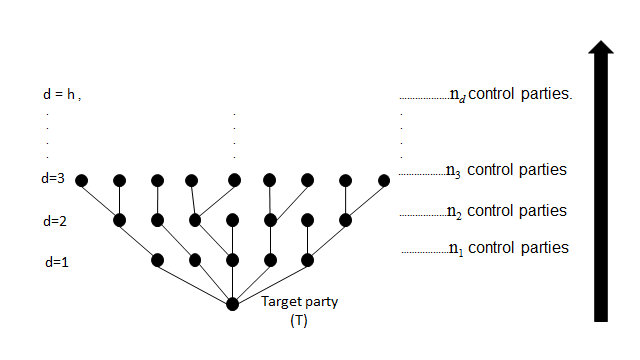
One defines the depth () of a control party as the number of edges present in the unique path from the target party. The height () of the rooted tree is the largest depth of the tree and the control party having an outward edge is called a leaf. Here, the number of control parties of the same depth is denoted as :
| (1) |
where is the total number of parties.
The rooted tree network is the most general network structure under the condition of optimal entanglement cost, which is ebits for remote parties. We now proceed to the details of the protocol of implementing non-local gates.
3 Simultaneous implementation of control-Hermitian gate
The simultaneous implementation of control-Hermitian gate is a realization of a number of control-Hermitian gates on a common target qubit in a quantum network. If the quantum state , connects remote parties, possessing a single qubit each, with the -th qubit as the target, then the desired state with the gate teleportation protocol will be . Here, denotes the control-Hertimian gate where, is the control qubit and the target. Although the protocol does not allow one to simultaneously implement a control-unitary gate, it is worth mentioning that many of important gates in quantum computation belong to this category.
For the sake of explicitness, we first consider a five party scenario, maintaining the entangled channel in a rooted-tree pattern, as depicted in Fig.2.
Let , , and be the four control parties (each control party is denoted as , where represents the depth and the location in that depth), wanting to simultaneously implement a controlled-Hermitian gate on a target party ().
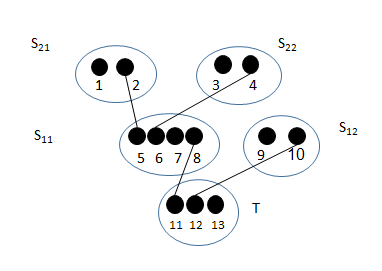
Let the five parties possess qubits 1, 3, 7, 9, 13 of an arbitrary state . and both share Bell states and , respectively with . and share Bell states and respectively with , such that
| (2) |
The protocol to implement simultaneous controlled-Hermitian gate, describing each implementation step is given below. Here, the implementation step is considered as a successive operation, which may be a quantum measurement or some other quantum operation or classical communication, as required. The following steps enumerate the implementation of protocol.
Step 1: All the leaves i.e., , and first apply Control-Not (, is the control and is the target) gate on their respective qubits , , .
Step 2: In the second step, both and measure their qubits 2 and 4 in the computational basis.
Step 3: They then convey the outcomes of the measurements to using classical resources.
Step 4: Depending on the outcome, performs the local operations as listed in Table 1, where are Pauli operators, with superscript ‘’ indicating the operating qubit.
| Outcome of measurements | Local operation after measurements |
|---|---|
Step 5: and measure their qubits 8 and 10 in the computational basis.
Step 6: Next, they convey the outcomes to target party .
Step 7: Based on their outcome then performs the local operations as described in Table 2,
| Outcome of measurements | Local operation after measurements |
|---|---|
Step 8: Subsequently, qubits 5 and 6 are measured in the Hadamard basis by and qubits 11 and 12 by .
Step 9: conveys the measurement outcomes of qubit 11 to , , ; and qubit 12 to . conveys the outcomes of qubits 5 and 6 to and respectively.
Step 10: Correspondingly the control parties perform following unitary operations to achieve the desired state shared by the parties,
| Outcome of measurements | Local operation after measurements |
|---|---|
The quantum circuit for the simultaneous implementation of gate as described by the above protocol is depicted in Fig.3. The entanglement resources (ebits) and classical communication resources (cbits) required to obtain the desired state are 4 and 10, respectively.
3.1 Protocol for -party simultaneous implementation of control-Hermitian gate
We now generalize the above protocol for remote parties, sharing an unknown -qubit state and maintaining an arbitrary rooted-tree entangled network. At first, all the control parties, located at leaves, apply a control-not gate on their respective pair of qubits taking the target qubit as the entangled qubit shared with another control party at the successive upper depth. In the next step, all the leaves, which are at the maximum depth measure their target qubit in computational basis and convey the outcomes to the successive control party located at . Based on the outcome of measurements, these control parties at depth perform local operations, i.e., if the outcome is they apply otherwise for every and , where is the entangled qubit shared with the control party at depth and is the entangled qubit with the qubit of control party at depth. is the unknown qubit of the state possessed by that party. These control parties then measure their target qubit in computational basis and convey the outcomes to the successive control party at . Similarly on the basis of outcomes, they perform local operations, measure their target qubit in computational basis and convey to the next control party. This process continues till the control parties at depth is reached. The control parties at depth measure their shared qubit and convey the outcomes to the target party . If the outcome is , then performs local operations , otherwise only for every , where is the entangled qubit shared with the control party at depth and is the unknown qubit of the type possessed by the target party. Subsequently, all the entangled qubits shared by the target party are measured in Hadamard basis and the outcomes of the measurements are conveyed to all the control parties, starting from the respective control party with whom the entangled state has been shared. The other control parties, except the ones in the leaves, measure the shared entangled qubit with the control party at successive lower depth in the Hadamard basis and convey the outcomes to them. Finally all the control parties perform on their possessed qubit of the state , if odd number of parties (including all the control parties with higher depth and the target party) get the measurement outcome .
Thus, for -party simultaneous implementation of a gate, the total number of cbits required is,
| (3) |
and the number of implementation steps is .
4 Implementation of multiparty control-unitary gate
We now proceed to describe the implementation of multiparty control-unitary gate on the rooted-tree network. The multiparty control-unitary is defined as a generalized form of a Toffoli gate for multi-qubit system, with one target party, where an arbitrary unitary gate acts on the target qubit, only if all the control qubits shared by the remote parties are . Thus, given an arbitrary quantum state , shared by remote parties, where -th qubit is the target, the desired state which will be realized by LOCC, is given by, . Here is denoted as the multiparty control-unitary gate, where are the control qubits and is the target.
To demonstrate the implementation, first we consider the same five party scenario as shown in Fig. 2. The qubit distribution is described in the earlier section, where the four control parties want to implement a controlled-unitary gate on an unknown state . The protocol for such implementation is described below:
Step 1: , and respectively apply , , ,
Step 2: Then and measure qubits 2 and 4 respectively in computational basis,
Step 3: Following that, they convey the outcomes, using classical communication resource to ,
Step 4: Now, applies the following local operations as described in Table 4, depending on the measurement outcomes:
| Outcome of measurements | Local operation after measurements |
|---|---|
Step 5: and measure qubits 8 and 10 respectively in the computational basis.
Step 6: They convey the outcomes to .
Step 7: applies the following unitary operation as shown in Table 5, where is the multiparty gate,
| Outcome of measurements | Local operation after measurements |
|---|---|
Step 8: measures qubits 11 and 12 in Hadamard basis.
Step 9: Next conveys the outcomes of qubits 11 and 12 to and respectively.
Step 10: and apply following gates, as shown in Table 6, according to the outcomes ( stands for control- gate),
| Outcome of measurements | Local operation after measurements |
|---|---|
Step 11: After that, measures qubits 5 and 6 in Hadamard basis.
Step 12: Next, conveys the outcomes of qubits 6 and 5 mesurements to and respectively.
Step 13: Finally and apply gates to obtain the desired state as described in Table 7 :
| Outcome of measurements | Local operation after measurements |
The pictorial representation of the above protocol is shown in Fig.4. The number of ebits and cbits required to implement a control-unitary gate are 4 and 8 respectively.
4.1 Protocol for implementation of -party control-unitary gate
The generation of the above protocol, for the qubit unknown state in an arbitrary rooted-tree network is as follows. At first, all the control parties which are located on the leaf apply a control-not gate on their qubits, taking the shared Bell state as the target qubit. In the next step, all the parties which are at maximum depth measure their target qubit in computational basis and convey the outcome to the control party at depth. Based on the outcomes of the measurements, these control parties at depth perform local operation , when the outcome is , otherwise for all and , where is the entangled qubit shared with the control party at depth, and is the entangled qubit shared with the control party at depth. is the qubit of the state possessed by that party. All these control parties then measure their target qubit in computational basis and convey the outcomes to the respective control party at depth. This process continues upto the control parties at depth, where the parties measure their entangled qubit and convey the outcomes to the target party. performs local operations , only if the outcome is for every , where is the entangled qubit shared with the control party at depth. Then applies , where is the unknown qubit of the state possessed by the target party and are entangled qubits shared with each of the control party at . After that, all the entangled qubits shared by the target party are measured in the Hadamard basis and the outcomes of the measurement is conveyed to all the control parties at depth . These control parties at , apply , only if the outcomes in the Bell shared qubit with target party is . Here are entangled qubits shared with the control parties at and is the qubit of the state possessed by that party. Then they measure qubits in Hadamard basis and convey the outcomes to respective control parties at lower depth. This continues upto the leaves, where they perform operation if the outcome of the shared entangled qubit by the control party in the successive upper depth is . This completes the protocol.
For implementation of -party control unitary gate, the total number of implementation steps is and the number of cbits required is,
| (4) |
The comparison of gate teleportation in the present rooted-tree network and the earlier networks are summarized in the Tables 8 and 9 given below,
| Network channel | Classical communication cost | No. of steps for implementation |
|---|---|---|
| Parallel | 7 | |
| Linear | ||
| Rooted-tree |
| Network channel | Classical communication cost | No. of steps for implementation |
|---|---|---|
| Parallel | 7 | |
| Linear | ||
| Rooted-tree |
5 Discussion
We have shown that a rooted-tree network is the most general entanglement distribution, which provides a fresh perspective for implementing non-local gates, locally from several control parties to a target party, under the condition of optimal entanglement cost. The explicit protocols of simultaneous implementation of Controlled-Hermitian gate and the multiparty Controlled-Unitary gate are described here in detail.
The earlier explored entangled networks, namely and configurations are specific cases of the rooted-tree network, where and respectively. Its worth mentioning that, for all the cases, the entanglement cost is ebits, which is optimal. It can be seen that, for a given , the classical communication cost and the number of steps for implementing simultaneous control-Hermitian gate increases as we go from parallel to linear network, through an arbitrary rooted-tree structure. For multiparty control-unitary gate, only the number of implementation steps increases. Significantly, the number of entangled states maintained by a party decreases as the height of rooted-tree increases. For example, in the scenario consider in Fig. 2, the maximum number of entangled states maintained by a party is 3; it is 4 for parallel and 2 for linear network. Thus the novelty of the rooted-tree entanglement distribution between remote parties lies in the fact that, it opens up the freedom of designing the entanglement network according to the capacity of maintaining entangled channels of each party, as well as the suitable number of implementation steps and the available classical communication resources.
In future, it will be of interest to investigate whether the classical communication cost for simultaneous control-Hermitian gate teleportation described here is optimal or not. Teleportation of other non-local gates using local operations and classical communication is also worth studying.
Acknowledgement:
D.S. acknowledges support from NCN grant 2013/08/M/ST2/00626. N.V. acknowledges Inspire programme undertaken by Department of Science and Technology, Government of India, for support.
References
- [1] J. Eisert, K. Jacobs, P. Papadopoulos, and M. B. Plenio, ‘Optimal local implementation of nonlocal quantum gates’, Phys. Rev. A 62, 052317 (2000).
- [2] J. I. Cirac, W. Dür, B. Kraus, and M. Lewenstein, ‘Entangling Operations and Their Implementation Using a Small Amount of Entanglement’, Phys. Rev. Lett. 86, 3 (2001).
- [3] D. Bouwmeester, J. W. Pan, K. Mattle, M. Eibl, H. Weinfurter, and A. Zeilinger, ‘Experimental quantum teleportation’, Nature (London) 390, 575 (1997).
- [4] Y.-F. Huang, X.-F. Ren, Y.-S. Zhang, L.-M. Duan, and G.-C. Guo, ‘Experimental Teleportation of a Quantum Controlled-NOT Gate’, Phys. Rev. Lett. 93, 240501 (2004).
- [5] S. M. Cohen, ‘Optimizing local protocols for implementing bipartite nonlocal unitary gates using prior entanglement and classical communication’, Phys. Rev. A 81, 062316 (2010).
- [6] L. Yu, R. B. Griffths, and S. M. Cohen, ‘Efficient implementation of bipartite nonlocal unitary gates using prior entanglement and classical communication’, Phys. Rev. A 81, 062315 (2010).
- [7] D. W. Berry, ‘Implementation of multipartite unitary operations with limited resources’, Phys. Rev. A 75, 032349 (2007).
- [8] H. Situ, and D. Qiu, ‘Investigating the implementation of restricted sets of multiqubit operations on distant qubits: a communication complexity perspective’, Quantum Information Processing 10, 5 (2011).
- [9] Controlled teleportation with the control of two groups of agents via entanglement Xiao-Ling He, Man Liu, Chui-Ping Yang, Quantum Information Processing 14, 7 (2015)
- [10] D. Saha, S. Nandan, and P. K. Panigrahi, ‘Local implementation of Non-local Quantum gates in linear entangled channel’, Journal of Quantum Information Science 4, 2 (2014).
- [11] Faithful teleportation via multi-particle quantum states in a network with many agents Min Jiang, Hui Li, Zeng-ke Zhang, Jia Zeng, Quantum Information Processing 11, 1 (2012)
- [12] C.-P. Yang, ‘A new protocol for constructing nonlocal n-qubit controlled-U gates’, Phys. Lett. A 372, 1380 (2008).
- [13] B. Groisman, and B. Reznik, ‘Implementing nonlocal gates with nonmaximally entangled states’, Phys. Rev. A 71, 032322 (2005).
- [14] C.-M. Yao, and B.-F. Cao, ‘Efficient implementation of a nonlocal gate with nonmaximal entanglement’, Phys. Lett. A 373, 1011 (2009).
- [15] A. Soeda, P. S. Turner, and M. Murao, ‘Entanglement Cost of Implementing Controlled-Unitary Operations’, Phys. Rev. Lett. 107, 180501 (2011).
- [16] D. Stahlke, and R. B. Griffiths, ‘Entanglement requirements for implementing bipartite unitary operations’, Phys. Rev. A 84, 032316 (2011).
- [17] C. Cong et. al., ‘Implementation of a nonlocal N-qubit conditional phase gate using the nitrogen–vacancy center and microtoroidal resonator coupled systems’, Chinese Phys. B 23, 040304 (2014).
- [18] S. Yokoyama et. al., ‘Nonlocal quantum gate on quantum continuous variables with minimum resources’, Phys. Rev. A 90, 012311 (2014).
- [19] H.-F. Wang, A.-D. Zhu, S. Zhang, and K.-H. Yeon, ‘Optically controlled phase gate and teleportation of a controlled-not gate for spin qubits in a quantum-dot–microcavity coupled system’, Phys. Rev. A 87, 062337 (2013).
- [20] C. H. Bennett, G. Brassard, C. Crepeau, R. Jozsa, A. Peres, and W. K. Wootters, ‘Teleporting an unknown quantum state via dual classical and Einstein-Podolsky-Rosen channels’, Phys. Rev. Lett. 70, 1895 (1993).
- [21] K. Mattle, H. Weinfurter, P. G. Kwiat, and A. Zeilinger, ‘Dense Coding in Experimental Quantum Communication’, Phys. Rev. Lett. 76, 4656 (1996).
- [22] C. H. Bennett, and S. J. Wiesner, ‘Communication via one and two particle operators on Einstein-Podolsky-Rosen states’, Phys. Rev. Lett. 69, 2881 (1992).
- [23] C. H. Bennett, P. Hayden, D. W. Leung, P. W. Shor, and A. Winter, ‘Remote preparation of quantum states’, Information Theory, IEEE Transactions on, IEEE 51, 56 (2005); P. K. Panigrahi, S. Karumanchi, and S. Muralidharan, ‘Minimal classical communication and measurement complexity for quantum information splitting of a two-qubit state’, Pramana 73, 499 (2009).
- [24] M. A. Nielsen, and I. L. Chuang, ‘Quantum computation and quantum information’, Cambridge University Press (2002).
- [25] V. Vedral, ‘Quantum entanglement’, Nature Physics 10, 256–258 (2014).
- [26] L.-B. Chen, and H. Lu, ‘Implementing a Nonlocal Toffoli Gate Using Partially Entangled Qubit Pairs’, Int. J. Theor. Phys. 50, 11 (2011).
- [27] R. Diestel, ‘Graph Theory’, Springer-Verlag, Heidelberg, Graduate Texts in Mathematics, Vol. 173 (2010).
- [28] Minimum cbits for remote preparation and measurement of a qubit, A.K. Pati, Phys.Rev.A 63,014302 (2001)