Dynamics of the free jets from nozzles of complex geometries
Abstract
The dynamics of the coherent structures in jets generated by nozzles of different shapes is analyzed through DNS at , by considering circular, square, fractal and star-like nozzles. The jets generated from orifices with corners, undergone a rotation proportional to the corner angular width: . The velocity at which this rotation occurs is also affected by the angle of the corners, being faster for fractal and star-like nozzles which have small . Therefore it has been found that the velocity of the rotation is associated with enhanced spreading and entraining characteristics. The jet evolution and its rotation are dictated by the vorticity field and, in particular, by the positive and negative layers generated at each corner. The comparison between the fractal and the star-like jets at this , suggested that the effect of the smaller scales generated by the fractal nozzle does not play a role in the development of the jet, that evolves as the star-like one.
1 Introduction
The starting jet formed by the sudden discharge of hot reaction products into a fuel-air mixture may have a large influence on the combustion process w1985 , with important implications in the transport, handling and storage of fuels, particularly hydrogen, and may also find application in engine ignition systems m1996 . The control of the jet evolution is strongly dependent on understanding the dynamics of the vortical structures, because the spreading is affected by the formation, interaction, merging, and breakdown of these structures.
The starting jet generated by a circular orifice shows a leading vortex ring followed by a slender jet stem, and the associated flow dynamics has been studied for constant density configurations by g1998 . They observed that, as the boundary layer separates at the orifice, the vortex sheet rolls up to form a toroidal vortex that travels downstream, entraining the outer fluid. As a result of the roll-up, a mixed core of reactants and combustion products should form at the jet head, providing a precursor ignition kernel where chemical reactions are enabled by the high temperature. Successively, hh1983 and hg1987 found that the entrainment of jets can be enhanced by using non-circular nozzles. The reason for the enhanced mixing and entrainment properties has been attributed to the characteristic rotation of the jet cross section, that occurs during its development in the stream-wise direction. This axis rotation results from self-induced deformation of vortex rings with non-uniform azimuthal curvature, and it has been observed using elliptic nozzles and nozzles with corners (gsphw1989 , th1989 ). In particular, laboratory experiments by gsphw1989 have shown that such rotation in square jets is responsible for enhancing the mixing of fluid in the neighborhood of the corner regions and near the jet outlet.
In the present work, DNS simulations at low Reynolds number have been performed to study the near-field evolution of the vortical structures generated by nozzles of complex shapes.
2 Numerical experiments
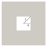
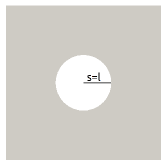
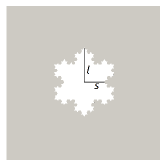
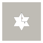
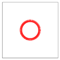
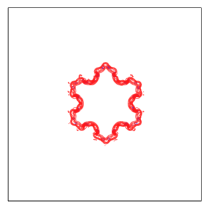
The details of the numerical scheme to solve the Navier-Stokes equations, together with the immersed boundary method used to reproduce the interaction between the flow and the solid, are described in ol2006 . The shape of the orifices considered are given in figure 1. The fractal orifice has been obtained with three iterations of the basic triangular geometry and all the orifices have been designed to have the same area, thus the solidity is the same in all the cases. is the equivalent diameter of the jets and it is since the area is equal to . At the inlet an uniform velocity profile is imposed and the orifice is located at . The simulations were performed at () in a computational domain discretized with points. The orifice is located in and is the downstream direction. Periodicity is assumed in and . In the plots the -coordinate is normalized with starting from : . \floatsetup[figure]style=plain,subcapbesideposition=top
[]
 \sidesubfloat[]
 \sidesubfloat[]
 \sidesubfloat[]
3 Results
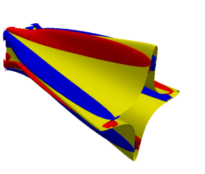
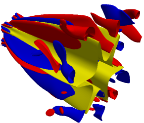
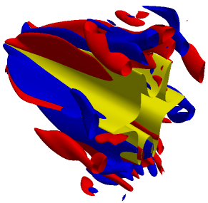
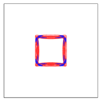
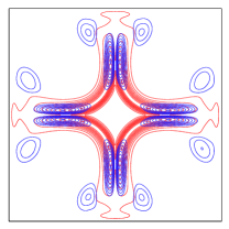
These DNS allow to study the vortex dynamics governing the evolution of the jets. At , the flow is laminar at the exit from the nozzle, and therefore it is possible to understand the causes leading to the jet deformation. In figure 2 the surface contour of are given for the square, circular, fractal and star-like jets in yellow. The flow generated by the circular orifice () is spread by viscous diffusion and maintains its circular shape downstream; in the other cases the shape is dictated by the hole only in the proximity of the orifice, and is lost is a short distance. At the end of the domain the flow is characterized by a number of corrugations that are rotated with respect to their initial position. For these are rotated of ; for only the six corrugations, related to the largest scales, are recognizable from the contour of , and these are rotated about with respect to the initial configuration. The same rotation occurs for . Therefore in the cases with corners, the rotation of the jet is proportional to the number of spikes, in particular: . This rotation was studied experimentally and numerically by ggp1995 and mmg1995 ; in particular mmg1995 considered square, rectangular and equilateral triangular orifices, observing a rotation for the first, an axis-switching ( rotation) for the second, and an overturning of for the latest. Considering only the initial and final position, the overturning of the equilateral triangle is indeed equivalent to a rotation, with . Therefore also the work of mmg1995 corroborates the present results of , which is valid only for the shapes with aspect ratio equal to . In fact the rectangular and the elliptic orifice, undergo a different . \floatsetup[figure]style=plain,subcapbesideposition=top
[]
 \sidesubfloat[]

[]
 \sidesubfloat[]
The location where the rotation of the jet terminates is also affected by the shape, and this length can be determined by monitoring the stream-wise variation of the half velocity width measured on the smallest (-direction) and largest (-direction) radii defined in figure 1. In figure 3a we reported the variation of the half-widths and non-dimensionalized by for , and while for we reported only because the jet remains circular. The half-width of the jet, at the given stream-wise location, is the distance from the center-line at which the axial velocity drops to half of its center-line value . If becomes larger than means that the jet has inverted its long and short diameters, and the rotation is completed. becomes larger than at for , for and for , thus and complete their rotation before . is also a fundamental quantity because indicates the stretching of the corner portions of the jet and, being approximately equal for all the jets, where grows faster, the corners undergo a stronger stretching. After the initial region where is spread faster than , at , reaches its maximum, while it continues to grow for . At the end of the domain of is larger than in because the former maintains its coherent shape longer, and the spreading is slower; on the other hand , as it will be shown later, produces an intricate flow pattern, where the vortex interactions make the jet to lose its coherent shape, and decreases.
To understand whether small scales corrugations play a role at small the fractal jet has been compared with . Figure 3a does not show large differences, suggesting that the smallest scales generated by the fractal jet die and do not influence the evolution far from the nozzle. The simulation allows to attribute the initial highest spreading of , not to the fractal corrugations, but to the angular width of the largest corners. In figure 3a it is reported also for to show that with this Reynolds number the radius of the jet remains almost unchanged along . \floatsetup[figure]style=plain,subcapbesideposition=top
[] \psfrag{X}[1]{$x^{*}$}\psfrag{Y}[1]{$r_{1/2}/D_{e}$}\psfrag{T}[1]{}\includegraphics[width=130.08731pt,angle={270}]{figure/bh_sqfr} \sidesubfloat[] \psfrag{X}[1]{$x^{*}$}\psfrag{Y}[1]{$\left\langle\Omega_{\theta}\right\rangle$, $\left\langle\Omega_{x}\right\rangle$}\psfrag{T}[1]{}\includegraphics[width=130.08731pt,angle={270}]{figure/otheta}
In the following paragraph the causes leading the jets to have different spreading are explained by looking at the vorticity fields which, being affected by the corners, dictate the evolution of the velocity structures previously described. The effect of corners is enlightened in figure 2, where the positive and negative contours of are respectively coloured in red and blue, and are overlapped to the contour of . The figure clearly shows that in , and , the thin layers of produced at the corners, are responsible for the rotation and successive stretching of the jets. The formation of can not be instead observed in . At the nozzle exit, in correspondence of every corner, a pair of thin layers of vortices forms. While these are convected downstream, the positive vortices come up against the negative ones generated by another corner, thus forming a new couple. This interaction between of opposite sign stretches the spikes and spreads the jet. For the fractal , of different size are produced at the inlet but, due to the low , the small patches die and do not affect the flow; therefore at a certain distance the jet is affected only by the six largest structures and does not differ from .
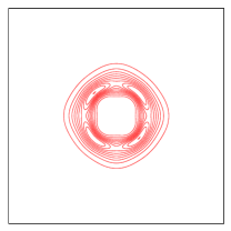
In addition to these vortical structures, at the end of the computational domain of (figure 2c) and (figure 2d), other structures with , that are not connected to the layers generated at the corners, are visible. These structures are due to the vortex dynamics that, through the processes of vortex-stretching and vortex-tilting, generates from the other vorticity components. In fact at the inlet and are also generated by the orifice, forming a corrugated sheet of intense vorticity. Such structures for the three jets , and are shown in figure 4, where isocontours of and , in the plane are plotted at two distances . The quantity for shows a structure with the same shape of the vorticity for a circular jet, evaluated in cylindrical coordinates vo1993 . In the figure the region with a clustering of the contour lines are those with the highest values of , and represents the boundaries of the vortex sheet. The increase of the width of this region with indicates the jet is spreading both towards the center-line and the surroundings. The other jets present a more complicated pattern at , because the jet spreading is greater than for , and the fluid transport between the jet and its surroundings is enhanced. This fast mechanism, triggered by the formed at the corners of the nozzle, is the cause for the intricate vorticity pattern, where also not generated at the inlet by the orifice is present. \floatsetup[figure]style=plain,subcapbesideposition=top
[]
 \sidesubfloat[]
 \sidesubfloat[]
[]
 \sidesubfloat[]
 \sidesubfloat[]
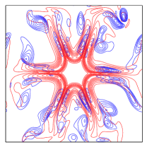
Figure 3b reports the evolution of and averaged in the plane and in time, along the stream wise direction. The values achieved by are larger than for any jet, and the plot shows that ; in fact the highest values are achieved by and that have a smaller with respect to . The plot shows that is null along the whole domain for the circular jet. In the other cases is approximately constant, until . The subsequent growth is due to the vorticity dynamics that produces from by vortex stretching and vortex tilting. The high is characterized by a first region where this quantity decreases, followed by a second region where it grows linearly. At the end the decrease is mainly due to the viscosity. The slope and the length of the linear region depend on the geometry of the orifice, in fact and , while is and the value of for remains approximately constant ().
4 Conclusion
The present DNS of the jets produced by nozzles of complex geometries at allowed to visualize the complex vortex dynamics, to increase the understanding of the jet evolution, in order to enhance the entrainment and the mixing. The jets generated from nozzles with sharp corners evolve differently from circular jets, that maintain an axisymmetric circular shape, due to the axis switching of the jet. This rotation is produced at the nozzle and is initiated by the vorticity self-induction process. The rotation of the jet has been related to the angular width of the corners () and, from the data in literature, the relationship between and seems to be valid for nozzles with aspect ratio . The velocity at which the rotation occurs can be measured by the growth rates of the and diagonals and it has been shown that, while is similar for all the nozzles with corners, is strongly affected by the shape. The growth of is associated with the stretching of the corrugations, in fact in and grows faster, the corners undergo a faster stretching, and this process contributes to enhance the spreading. The deformation of the jet is linked to the vortex dynamics because patches of are formed at the corners. These thin layers are convected downstream and in turn deform the jet. The spikes of the jet are stretched by these vortices and consequently the structure is spread more rapidly, higher is the strength of the patches. As a result the fluid transport between the jet and its surroundings is enhanced, so as the mixedness. The low Reynolds number assumption guarantees that the flow remains laminar in the near-field and, in such condition, the wider range of scales generated by the fractal nozzle, does not affect the flow, therefore the evolution of and does not show large differences.
References
- (1) F.A. Williams. Combustion Theory Addison-Wesley, Redwood City, CA, 2nd ed.: 1985.
- (2) E. Murase, S. Ono, K. Hanada and A.K. Oppenheim. Initiation of combustion in lean mixtures by flame jets Comb. Sci. Tech., 113: 1996.
- (3) M. Gharib, E. Rambod, and K. Shariff. A universal time scale for vortex ring formation J. Fluid Mech., 360, 1998.
- (4) H. S. Husain and A. K. M. F. Hussain. Controlled Excitation of Elliptic Jets Phys. Fluids, 26: 2763, 1983.
- (5) C. Ho and E. Gutmark. Vortex induction and mass entrainment in a small-aspect-ratio elliptic jet J. Fluid Mech., 179, 1987.
- (6) E. Gutmark, K. C. Schadow, T. P. Parr, D. M. Hanson-Parr and K. J. Wilson Noncircular jets in combustion systems Exp. Fluids, 7, 1989
- (7) K. Toyoda and F. Hussain in Proceedings of the 4th Asian Congress of Fluid Mechanics, Hong Kong, August 1989, pp. A117-A127.
- (8) P. Orlandi and S. Leonardi. DNS of turbulent channel flows with two- and three-dimensional roughness J. of Turb., 7-53, 2006
- (9) F. F. Grinstein, E. Gutmark and T. Parr. Near field dynamics of subsonic free square jets. A computational and experimental study Phys. Fluids, 7, 1995
- (10) R. S. Miller, C. K. Madnia and P. Givi. Numerical simulations of non-circular jets Computer and Fluids, 24, 1995
- (11) R. Verzicco, P. Orlandi. Direct simulations of the transitional regime of a circular jet Phys. Fluids, 6: 751-759, 1993
- (12) S. B. Pope. Turbulent Flows, Cambridge, 2000