Lamellar Diblock Copolymers on Rough Substrates: Self-consistent Field Theory Studies
Abstract
We present numerical calculations of lamellar phases of di-block copolymers (BCP) confined between two surfaces, where the top surface is flat and the bottom one is corrugated. The corrugated substrate is assumed to have a single -mode of lateral undulations with a wavenumber and amplitude . We focus on the effects of substrate roughness, parameterized by the dimensionless quantity, , on the relative stability between parallel and perpendicular orientations of the lamellar phase. The competition between film confinement, energy cost of elastic deformation and gain in surface energy induces a parallel-to-perpendicular transition of the BCP lamellae. Employing self-consistent field theory (SCFT), we study the critical value, , corresponding to this transition. The value increases as function of the surface preference towards one of the two BCP components, and as function of film thickness. But, decreases with increasing values of the Flory-Huggins parameter, . Our findings are equivalent to stating that the critical value decreases as the BCP molecular weight or the natural BCP periodicity increases. We further show that the rough substrate can overcome the formation of parallel lamellae in cases where the top surface has a preference towards one of the two BCP components. Our results are in good agreement with previous experiments, and highlight the physical conditions behind the perpendicular orientation of lamellar phases, as is desired in nanolithography and other industrial applications.
I Introduction
Block copolymers (BCP) are polymer systems where each of their chains is composed of two or more chemically-distinct homopolymer blocks, covalently tethered together. As a result, BCP systems can spontaneously self-assemble at thermodynamical equilibrium into exquisitely ordered nano-structures Glenn06 . The phase behavior of di-BCP melts, where each linear chain is composed of two blocks, (denoted hereafter as A and B), has been studied extensively in recent decades, and shows a rich variety of three-dimensional morphologies including lamellae, hexagonally close-packed cylinders, BCC packing of spheres, and gyroid networks Matsen94 ; Bates94 . The characteristic length scale in these well-defined structural phases ranges from a few nanometers to hundreds of nanometers, and can offer an attractive alternative to patterning technology Kim10 ; Bates90 . Besides applications in nano-lithography, BCP films may offer novel opportunities in more traditional applications such as adhesive, hydrophobic and anti-reflective surfaces, as well as in the textile industry Sinturel13 .
Most of the BCP applications rely on casting them as thin films since this is the most appropriate form to construct a surface pattern that can later be transferred onto a substrate, with potential applications as functional nanoscale devices Hamley09 . A perpendicular orientation of BCP lamellae or cylinders, with respect to the underlying substrate, is usually desirable for most material and engineering applications Bates14 . During recent decades, various techniques have been developed to obtain such perpendicular lamellae or cylinders, including nonpreferential (neutral) interfaces Kim10 ; Liu09 , topographically varying substrates Park09a or top surfaces Man11 ; Man12 , variations in polymeric block architecture Khanna06 ; Matsen10 and film thickness, as well as solvent annealing Sinturel13 .
It is also possible to use corrugated substrates to obtain perpendicular BCP lamellae or cylinders. Sivaniah et al Sivaniah03 ; Sivaniah05 reported the effect of substrate roughness on the orientation of lamellae of symmetric poly(styrene)-block-poly(methyl methacrylate) (PS-b-PMMA). They identified a critical substrate roughness, , above which a perpendicular orientation was observed, where and are the lateral wavenumber and its amplitude, respectively. They also found that the value of varies with BCP molecular weight (or the periodicity of BCP lamellae). In a more recent study, Kulkarni et al Kulkarni12 extended the results to include fractal substrate topography. A high fractal dimension of the rough substrate, in conjunction with an optimal surface energy of PS-b-PMMA in contact with the substrate, results in a complete perpendicular orientation of lamellar micro-domains.
In a separate work, Kim et al Char13 investigated a film of PS-b-PMMA placed on an ordered nanoparticle (NP) monolayer. The substrate roughness is described by the parameter , where and are the wavenumber of substrate roughness and the radius of NP, respectively. A transition from parallel to perpendicular orientation of BCP lamellae or cylinders has been found by increasing the value of . Furthermore, it was shown that the orientation of thin films of BCP is strongly influenced by the film thickness. This is due to the commensurability matching between film thickness and domain spacing.
In addition to the experimental situation, there are few theoretical works addressing the self-assembly of BCP films on corrugated surfaces. Turner and Joanny Turner1992 , and Tsori et al Yoav03 ; Yoav05 used the analogy between smectic liquid crystals and lamellar BCP, and compared the phenomenological free energy of parallel and perpendicular lamellae on corrugated substrates. In Refs. Yoav03 ; Yoav05 it was shown that for a fixed corrugation periodicity, the perpendicular orientation is preferred for large corrugation amplitude and/or large lamellae periodicity. Moreover, for a fixed BCP natural periodicity, the perpendicular orientation is preferred for surfaces having large corrugation amplitude at short wavelengths.
Motivated by previous experimental works Kulkarni12 , Ranjan et al Ranjan12 conducted a scaling analysis of a single BCP lamella on fractal surfaces, which gives additional evidence that the substrate fractal dimension is an important factor in directing the orientation of BCP lamellae. Even more recently, Ye et al Ye14 studied morphological properties of lamellae-forming di-BCPs on substrates with square-wave grating patterns by using self-consistent field theory (SCFT). They found three possible lamellar orientations with respect to the substrate and trench direction, but without addressing the key factors that determine the critical substrate roughness at the parallel-to-perpendicular phase-transition of BCP micro-domains.
We note that these previous studies have provided insight on how substrate roughness affects the relative stability of parallel and perpendicular BCP micro-domains on non-flat surfaces. However, to date, systematic studies addressing the combined effect of substrate corrugation amplitude and lateral wavenumber, film thickness and BCP periodicity on the domain orientation of BCP films are still missing. In this paper, we present a comprehensive and detailed SCFT study of di-BCP films constrained between a top flat surface and a bottom corrugated substrate. Our aim is to investigate the role played by substrate geometry, relative surface preference of the two BCP components, and BCP film properties, including film thickness, the Flory-Huggins parameter, , between the two monomers, and the lamellar periodicity, on the parallel-to-perpendicular phase-transition.
In the next section, we introduced the SCFT formalism, and our numerical scheme. In Sec. III, the corrugated surface and BCP film design are presented, while in Sec. IV, we show the calculated phase diagrams of BCP lamellae on corrugated substrates. Discussion of our results and comparison with previous models and experiments are presented in Sec. V, followed by a summary and conclusions.
II Theoretical Framework
II.1 The SCFT Scheme
We use self-consistent field theory (SCFT) to investigate the lamellar phase of A/B di-BCP confined between two surfaces, where the top surface is flat and the bottom one is corrugated. We consider a melt of chains, each composed of monomers. For simplicity, the Kuhn length, , is assumed to be the same for the A and B monomers, yielding an equality between the molar fraction and the volume one. The A-component molar fraction is and that of the B-component is . The BCP film has a total volume , lateral area , and thickness . Hereafter, we concentrate on symmetric di-BCP, i.e., .
In order to facilitate the numerical convergence, it is convenient to replace the sharp interface between the BCP film and the hard bounding surfaces by a “softer” wall with a smeared interface having a small width. This is done by introducing an artificial third (wall) component Matsen97 ; Bosse07 ; Glenn06 . The local incompressibility condition is , where , and are the A, B and wall volume fractions within our simulation box, respectively. This condition is replaced with a compressible one, by adding an energetic penalty cost for local density deviations from the incompressibility condition. The penalty term is written as:
| (1) |
and has a magnitude controlled by an “energy” parameter (in units of , where is the Boltzmann constant and is the temperature).
The direction parallel to the substrate is chosen to be along the -direction, and the perpendicular one is in the -direction. The system is assumed to be translational invariant in the third -direction, which means that the numerical calculations are performed in a two-dimensional (2d) box. All lengths, hereafter, are rescaled with the chain radius of gyration, . With these conventions, the Hamiltonian of the BCP film confined between two surfaces can be expressed as a functional of two local fields: a pressure field and an exchange potential field Glenn06 ,
| (2) | |||||
where is a normalization factor, is the total number density, is the entire volume (including the walls) of the simulation box, is the total number of “wall monomers”, and is the dimensionless volume fraction of the polymer. The Flory-Huggins parameter between the A and B monomers is , and is the relative interaction between the wall and the A/B components, where and are the interaction parameters between the wall (as a 3rd component) and the A or B components, respectively. For example, a positive means that the surface prefers the A component. For simplicity, hereafter we absorb the factor of into the definition of and : and .
The functional is the single-chain partition function in the presence of the two conjugate fields, and , where the propagator is the solution of the modified diffusion equation,
| (3) |
satisfying the initial condition . for and for , where is the curvilinear coordinate along the A/B chain contour. Finally, is the polymer volume fraction averaged over .
Within the mean-field approximation, we can obtain the thermodynamic properties of the confined BCP film from a variational principle of the Hamiltonian in Eq. (2),
| (4) |
This means that
Equation (II.1) can be solved numerically by solving the modified diffusion equation, Eq. (3), with spatially-periodic boundary conditions and the following temporal relaxation equations,
| (6) |
We use the well-documented pseudo-spectral method with FFTW to solve the modified diffusion equation, and an explicit Euler scheme (1st order in the iteration time) to update the field configurations to their saddle points. A detailed formulation of the numerical procedures for the SCFT model and their implementation to BCP systems can be found elsewhere Bosse07 ; Hur09 ; Takahashi12 .
II.2 Corrugated Substrate Design
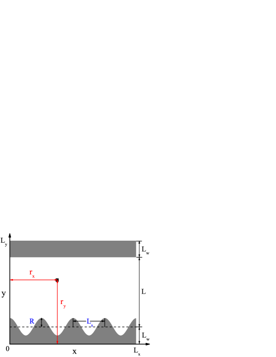
Our simulation setup is shown schematically in Fig. 1, where the 2d simulation box of size includes the BCP film and the solid boundaries, and the average wall thickness is . Hence, the average BCP film thickness is given by . The top surface is flat, while the bottom surface is corrugated, and is described by a height function
| (7) |
having a single -mode with wavenumber and amplitude .
The wall density, , has a pre-assigned shape that is fixed (frozen) during the iterations. The top flat wall is modelled as a rectangle of size (Fig. 1), and characterized by a smoothly-varying wall function:
| (8) |
where parameterizes the interface width, and is the distance from the bottom box boundary. For the bottom corrugated surface, we impose a similar smoothly-varying wall function
| (9) |
where is the distance to the left box boundary. Such a definition means that inside the wall region of the rectangular box, and inside the BCP film. However, it generates a “soft” interface that is characterized by a narrow and smooth transition region of thickness . Hereafter, we set and for all simulations, following previous simulation work Takahashi12 . Our results are not sensitive for values of , and consequently is chosen for converge purposes. The value is large enough to model an incompressible system, yet facilitate numerical converge.
III Results
III.1 The Parallel and Perpendicular Lamellar Orientations
Symmetric BCPs yield thermodynamically stable lamellar phases with a bulk periodicity, . The immediate effect of the corrugation can be seen in Fig. 2. When the substrate roughness is large enough, (Fig. 2(a)), the surface-induce distortion only propagates up to the second layer and all other lamellae are unperturbed. However, for small substrate roughness, as in Fig. 2(b), the lamellae follow the surface contour, and the distortion are longer range. It is important to note that the results are obtained for a finite film thickness where the top surface is flat and neutral (). These results have smaller penetration length as compared with previous scaling Turner1992 ; Yoav03 ; Yoav05 for infinite stacks of lamellae, where the penetration length scales as .
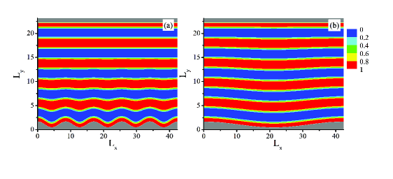
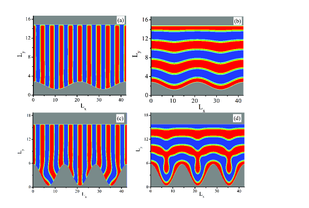
Figure 3 shows examples of parallel and perpendicular lamellar phases in contact with a corrugated substrate in the strong segregation regime, . The bottom substrate in (a) and (b), having a moderate roughness, , is attractive to the A component (marked in red) with , while the top surface is neutral (). Clearly, the perpendicular lamellar phase (L⟂) in (a) is almost unperturbed, as compared to its bulk phase. However, the parallel one (L∥) in (b) adjusts its shape due to the surface corrugation. This is a result of the competition between the cost of BCP elastic deformation close to the corrugated surface and the gain in its surface energy. The results both in (a) and (b) agree well with previous analytical results carried out by Tsori et al Yoav03 ; Yoav05 .
For the case of large substrate roughness, , the lamellae are strongly deformed, and it is hard to recognize whether their equilibrium structure is an L⟂ or L∥ phase. Such pronounced deformations are shown in Fig. 3(c) and (d), where the bottom substrate roughness is , while all other conditions are the same as in (a) and (b). To be able to have meaningful predictions, we hereafter consider only substrates that have moderate roughness, , and surface preference that is less than the interaction between the A and B components, .
When the BCP film thickness, , differs from an integer multiple of , the BCP chains have to stretched or compressed, as the total film volume is incompressible and space-filling (in our formalism, is large enough and model an incompressible system). In order to minimize such a confinement effect and focus mainly on how surface roughness affects the lamellar orientation, we adjust the box size such that the film thickness corresponds to a local minimum of the L∥ free energy. This is done by investigating the free energy difference between parallel and perpendicular lamellae, , where and are, respectively, the lamellar free-energies of the two orientations.

Figure 4 shows the dependence of on with . We repeat the calculation of for various lamellar layers, , between two flat and neutral surfaces. Clearly, the rescaled has always a local minimum when equals to an integer number times the natural periodicity, , in accord with previous SCFT calculations of Takahashi et al Takahashi12 . It is known that depends on the value of . Therefore, for different values of we have to repeat this calculation and obtain the free energy in order to find the appropriate local minima, as in Fig. 4.
It is important to note that when a thin BCP film is confined between two surfaces, is also a function of the film thickness, , and differs from its bulk value Takahashi12 . Moreover, the free energy of confined BCP films also depends on the surface preference field, Matsen97 ; Geisinger99 ; Man10 ; Tsori01 . Therefore, the parameters , and play an important role in determining whether the equilibrium orientation will be parallel (L∥) or perpendicular (L⟂), as will be further presented below.
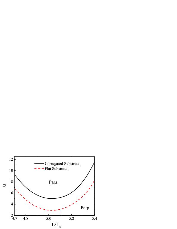
We first compute the perp-to-para (L⟂–L∥) phase diagram (shown in Fig. 5) in terms of the film rescaled thickness, , and bottom surface preference, , for a corrugated substrate. For comparison, the calculation is then repeated for another system having a flat bottom surface, with the same parameters: , and . The film thickness varies around : . The wavenumber of the corrugated substrate is , while the corrugation magnitude is fixed, , resulting a substrate roughness . The phase diagram is obtained by starting with an initial condition of either an L⟂ phase of ten periods or an L∥ of five periods. After numerical convergence, the corresponding free energies are compared. The results show that the rough substrate greatly affects the phase diagram as compared with flat substrate. The L⟂ – L∥ phase-transition line for the corrugated case is shifted upward, which means that the L⟂ phase has a larger stability range for rough substrates than for flat ones. This conclusion qualitatively agrees with previous analytical and experimental studies Yoav05 ; Sivaniah05 ; Char13 . It shows that rough substrates, just like chemical-patterned substrates and nano-Imprint surfaces Man10 , can enhance the stability of the L⟂ phase as compared with a flat substrate with the same surface preference field, .
III.2 The Substrate Effect on Para-to-Perp Transition

We proceed by studying quantitatively the effect of substrate roughness on the relative stability of the L⟂ and L∥ phases. We focus on the role played by i) the substrate geometry, including lateral wavenumber, , and roughness amplitude, , ii) the relative surface preference towards the two BCP components, , and iii) BCP film properties, including film thickness, , the Flory-Huggins parameter, , as well as the BCP natural periodicity, on the L∥–L⟂ phase-transition.
Figure 6 shows the L∥–L⟂ phase diagram in terms of the corrugation parameters, and , for a fixed bottom substrate preference () and a flat neutral top surface (). For fixed , while increasing , an L∥-to-L⟂ phase-transition is reached because the elastic deformation of the L∥ lamellae along the corrugated surface becomes bigger, favoring the L⟂ orientation. For fixed value of , an increase of also induces an L∥-to-L⟂ phase-transition. This can be understood as smaller (while keeping constant) means that the substrate effectively is flatter, and the L∥ lamellae are losing less elastic deformation energy. In the limit of (corresponding to an unrealizable large simulation box), the substrate approaches to a flat substrate. Then, the L∥ phase will be more stable than L⟂ because of the substrate preference towards one of the two BCP components.
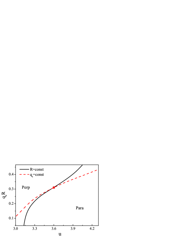
As discussed in the section III.A above, the surface preference, , is an important factor in determining the final lamellar orientation. Moreover, is usually used to parameterize the substrate roughness in experiments. We investigate the effects of the substrate on the critical value, , corresponding to the L∥–L⟂ phase-transition, while keeping the top surface neutral () and flat (see Fig. 7). Our results show that increases as function of . This means that for larger , larger substrate roughness is needed to induce an L∥-to-L⟂ phase-transition. This is due to the competition between the energy cost of elastic deformation and gain in surface energy. Increasing leads to more elastic deformation in the L∥ phase as compared with L⟂, resulting in a phase transition from an L∥ to an L⟂ phase. Oppositely, increasing makes the L∥ phase more stable because of the gain in surface energy, leading to a phase transition from L⟂ to L∥.
The critical substrate roughness for various rescaled BCP film thicknesses
| 2 | 3 | 4 | 5 | 6 | |
|---|---|---|---|---|---|
| 0.15 | 0.17 | 0.18 | 0.21 | 0.26 |
We present in Fig. 7 two ways to change the values of . First, we fix the corrugation amplitude, , and change the wavenumber discretely by taking these values as , where is the number of lateral periods of the substrate. Next, we fix and change from to . The simulation box size is set to , , and . For the calculations, L⟂ has ten BCP lamellar periods as its initial condition while L∥ has five. After convergence, the L⟂ and L∥ free energies are compared, and clearly, for both phases, is an increasing function of . However, for the same value of , the value of is different for constant and constant , with a difference of the order of . This indicates that is not exactly a scaling field for the L∥–L⟂ phase-transition. The reason is that the contour length of the substrate has a small difference (also on the order of ) for different combinations of and , while keeping their product the same. Such differences will further result in a different elastic deformation and surface energies of the film.
III.3 The Film Effect on the Para-to-Perp Phase Transition
Another important parameter that affects is the BCP film thickness, . Table I presents the dependence of on , obtained with fixed preference of the bottom and top surfaces, and , respectively. We add a small top surface preference, , to mimic the experiments, where BCPs usually have non-zero preference in their surface interaction with the air. More discussion about the top surface preference effects on the L∥–L⟂ phase-transition will be addressed in the section IV. As mentioned in Fig. 4, we choose the film thickness to be an integer multiple of the L∥ periodicity, i.e. , where , in order to minimize the film confinement effects. The L∥ free energy is compared with the L⟂ one with , while all other parameters are kept the same. The numerical results indicate that increases for thicker BCP film. This is understandable because the elastic deformation induced by the corrugated substrate is a surface effect with limited penetration into the BCP film. Therefore, larger values are needed to induce the L∥-to-L⟂ phase-transition for thicker films. Finally, we examine the effect of (or ) on the L∥–L⟂ phase-transition in Fig. 8. As mentioned above, varying will also change the BCP lamellar periodicity, . In order to stay in the minimal confinement free-energy, we set , where varies for different . Because the minimum in corresponds to , we obtain the value of for different by examining the dependence of on , while keeping fixed. After determining the values of , we can adjust our simulation box accordingly. The values for different are shown in Table II, where it can be seen that is an increasing function of Sivaniah08 . For all calculations in Fig. 8, the parameters are: , and . The values for different are set to fulfill (see Table II). From Fig. 8(a), one sees that decreases as increases. This can be understood because when increases, the lamellar periodicity, , also increases, and the local deformation of BCP lamellae becomes larger. For example, in the limit of , the corrugated substrate is equivalent to a flat one, and the BCP lamellae will not be deformed anymore, resulting in no elastic deformation. In other words, the energy cost of the elastic deformation increases as increases. Then, smaller values of are needed to induce the L∥-to-L⟂ phase-transition. The tendency of to decrease when increases is shown in Fig. 8(b) and is consistent with the results in Table I. When increases, it means that the value of in Table I decreases, and the same tendency of on is obtained.
Lamellar periodicity, , and average film thickness, , for various values.
| 18 | 20 | 22 | 25 | 28 | |
|---|---|---|---|---|---|
| 3.90 | 4.00 | 4.10 | 4.25 | 4.35 | |
| 11.7 | 12.00 | 12.30 | 12.75 | 13.05 |


IV Discussion
IV.1 Comparison with Experiments
Our study has been motivated by the experimental works of Sivaniah et al Sivaniah05 and Char’s group Char13 . In Ref. 16, PS-b-PMMA films are casted onto an array of polyimide (PIM) substrates having different roughness. The study found the critical roughness of the PIM substrate, , separating the stable L⟂ lamellae for from the region where the L∥ lamellae are more stable, . In a more recent work by Char’s group Char13 , both lamellar and cylindrical phases of PS-b-PMMA were spin-coated onto two different substrates covered with an ordered nanoparticle (NP) monolayer. In the first set-up, the NP size is and its repeat period is , resulting in . For the second set-up, the NP size is , the repeat period is , which leads to . For both lamellae and cylinders, orientation was obtained in the first case , and orientation for the second one . The conclusion from these experiments is that increasing the substrate roughness can induce an L∥-to-L⟂ phase-transition. All of our results nicely support these findings, although we can justify less our SCFT results in a quantitative manner for . Sivaniah et al Sivaniah05 have also shown that the value of varies with the BCP molecular weight. Keeping all experimental conditions the same, the value of for 38K-38K PS-b-PMMA was found to be and for 18K-18K is it . Furthermore, the natural periodicity for the 38K-38K system is , and for 18K-18K it is . Because the experiments were conducted for only two BCP chain lengths, it was not possible to infer any trend of lower values for higher molecular weights. However, our results indicate such a trend, where the values of increase from to , and corresponds to a decrease of .
IV.2 Comparison with Previous Models
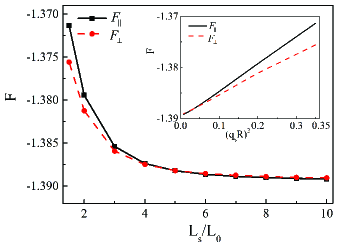
In a closely-related analytical study, Tsori et al Yoav03 ; Yoav05 used the analogy between smectic liquid crystals and lamellar BCP, and compared the phenomenological free-energies of L∥ and L⟂ phases on corrugated substrate, and study their relative stability. Their results can be summarized by the following three findings. While keeping all other parameters fixed, these authors found that i) increasing induces an L∥-to-L⟂ phase-transition; ii) increasing results in an L⟂-to-L∥ phase-transition; and, iii) increasing leads to an L∥-to-L⟂ phase-transition. Our findings agree with the first finding of Tsori et al, as well as with the experimental findings discussed in the section IV.A above. Increasing the value of (while all other parameters are fixed) means larger substrate roughness, and therefore, it induces an L∥ – L⟂ phase-transition. However, the second and third findings of Tsori et al are contrary to experimental trends Sivaniah05 , as well as to our SCFT calculations. One of the results of Tsori et al Yoav03 ; Yoav05 is that is an increasing function of the lateral wavelength, , while scales as . However, our SCFT results show an opposite trend for , while the same scaling for . This behavior of the two free energies is shown in Fig. 9, and in the inset the scaling with can be clearly seen. We note that in an even earlier work by Turner and Joanny Turner1992 , the free energy of both and stack on a corrugated substrate were found to scale as (while all other parameters are fixed). We conjecture that the discrepancy between our SCFT and the previous analytical results Turner1992 ; Yoav03 ; Yoav05 is due mainly to two reasons. One, is the fact that our stack has a finite width and the top surface is affecting the penetration length, and hence the delicate balance between the two orientations. The second reason is related to local deformations of BCP chains close to the corrugated substrate. These deformations are not well described within models that draw on the analogy with a continuum theory of smectic liquid crystals, and which assumes small and gradual deformations.
IV.3 Non-neutral Air/Polymer Interface
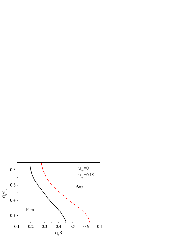
It is known that when the top surface (polymer film/air) has a preference toward one of the two BCP blocks, it can induce an L∥ orientation inside the film. In many applications (e.g., in nanolithography), it is highly desired to circumvent the phase by using the so-called ‘top coats’ Bates12 ; Yoshida13 ; Son14 . Moreover, Khanna et al Khanna06 in experiments and Matsen Matsen10 in theory have shown that the BCP architecture can also affect the polymer/air surface tension, and facilitates the formation of L⟂ lamellae. Figure 10 shows a comparison of the L∥–L⟂ phase diagram in terms of and between a system with a top surface field, , and a second system with a neutral top surface, (same as in Fig. 5). From Fig. 10 it can be seen to what degree the non-zero top surface affects the relatively stability of the L⟂ and L∥ phases. When a small surface preference is added to the top surface, the L∥–L⟂ phase-transition line shifts to the right (the red dashed line); namely, the transition value, increases. Our study is instrumental as it shows a possible solution utilizing a rough substrate to overcome the parallel orientation induced by the commonly-found air/film preference, . Therefore, combining the ‘top coats’, varying BCP architecture, as well as employing rough substrates may offer an effective way to obtain perpendicular orientation of BCP nano-structures, even in cases where BCPs have significant different surface tension between the air and the two blocks of the BCP.
V Conclusions
In this article, we address the influence of a non-flat substrate on the relative stability between the two orientations, L∥ and L⟂, of lamellar BCP phases. The thin lamellar film is confined between a top flat surface and bottom corrugated substrate of a shape, , with a single -mode of lateral undulations. The competition between the energy cost of elastic deformation and gain in surface energy of BCP lamellae results in an L∥–L⟂ phase-transition. We comprehensively and systematically studied the combined effect of the rough substrate with lateral wavenumber, , and magnitude , as well as the interface energy between the BCP and the surface, film thickness and the Flory parameter on the L∥-to-L⟂ phase-transition. Our results show that increasing the substrate roughness, , induces an L∥-to-L⟂ phase-transition. Moreover, the critical value of the substrate roughness, , corresponding to the L∥–L⟂ phase-transition, increases as the surface preference towards one of the two blocks, , increases, or as the film thickness becomes thicker. On the other hand, it decreases when the Flory parameter, , or the natural periodicity, , increases. We focused in this study on a few key factors that enhance or induce the phase-transition from L∥ into the L⟂ phase, as is desired in applications. As detailed in the section IV, our predictions are consistent with several experimental findings. Furthermore, as our study is systematic, its predictions can be further tested experimentally by using di-BCP with different chain lengths and periodicities, and by changing in a tunable fashion the corrugated substrate, the top surface preference as well as the film thickness, in order to determine the optimal condition for the enhance stability of the L⟂ phase. In addition to the effect of substrate roughness on the parallel-to-perpendicular orientation transition, corrugated substrates have been shown to improve in-plane ordering of thin BCP films Park09b ; Park09a ; Vega13 . We hope that in the future more detailed 3d calculations will shed more light on various possibilities that non-flat substrates may improve the in-plane ordering and defect annihilation of BCP lamellar phases.
Acknowledgement. This work was supported in part by grants 21404003, 21434001 and 21374011 of the National Natural Science Foundation of China (NSFC), the 973 program of the Ministry of Science and Technology (MOST) 2011CB808502, and the Fundamental Research Funds for the Central Universities. We thank Henri Orland and Yoav Tsori for useful discussions and comments. D.A. acknowledges support from the Israel Science Foundation (ISF) under Grant No. 438/12 and the United States–Israel Binational Science Foundation (BSF) under Grant No. 2012/060.
References
- (1) Fredrickson, G. H. The Equilibrium Theory of Inhomogeneous Polymers, (Oxford University Press, New York, 2006).
- (2) Matsen, M. W.; Schick, M. Phys. Rev. Lett. , 72, 2660.
- (3) Bates, F. S.; Schulz, M. F.; Khandpur, A. K.; Frster, S.; Rosedale, J. H.; Almdal, K.; Mortensen, K. Faraday Discussions , 98, 7.
- (4) Kim, H.-C.; Park, S.-M.; Hinsberg, W. D. Chem. Rev. , 110, 146.
- (5) Bates, F. S.; Fredrickson, G. H. Annu. Rev. Phys. Chem. , 41, 525.
- (6) Sinturel, C.; Morris, V. M.; Hillmyer, M. A. Macromolecules , 46, 5399.
- (7) Hamley, I. W. Prog. Polym. Sci. , 34, 1161.
- (8) Bates, C. M.; Maher, M. J.; Janes, D. W.; Ellison, C. J. ; Willson, C. G. Macromolecules , 47, 2.
- (9) Liu, P.-H.; Thbault, P.; Guenoun, P.; Daillant, J. Macromolecules , 42, 9609.
- (10) Park, S.-M.; Berry, B. C.; Dobisz, E.; Kim, H.-C. Soft Matter , 5, 957.
- (11) Man, X.-K.; Andelman, D.; Orland, H.; Thbault, P.; Liu, P.-H.; Guenoun, P.; Daillant, J.; Landis, S.; Macromoleclues , 44, 2206.
- (12) Thbault, P.; Niedermayer, S.; Landis, S.; Chaix, N.; Guenoun, P.; Daillant, J.; Man, X.-K.; Andelman, D.; Orland, H. Adv. Mater. , 24, 1952.
- (13) Khanna, V.; Cochran, E. W.; Hexemer, A.; Stein, G. E.; Fredrickson, G. H.; Kramer, E. J.; Li, X.; Wang, J.; Hahn, S. F. Macromolecules , 39, 9346.
- (14) Matsen, M. W. Macromolecules , 43, 1671.
- (15) Sivaniah, E.; Hayashi, H.; Iino, M.; Hashimoto, T. Macromolecules , 36, 5894.
- (16) Sivaniah, E.; Hayashi, H.; Matsubara, S.; Kiyono, S.; Hashimoto, T.; Fukunaga, K.; Kramer, E. J.; Mates, T. Macromolecules , 38, 1837.
- (17) Kulkarni, M. M.; Yager, K. G.; Sharma, A.; Karim, A. Macromolecules , 45, 4303.
- (18) Kim, T.; Wooh, S.; Son, J. G.; Char, K. Macromolecules , 46, 8144.
- (19) Turner, M. S.; Joanny, J.-F. Macromolecules , 25, 6681.
- (20) Tsori, Y.; Andelman, D. Macromolecules , 36, 8560.
- (21) Tsori, Y.; Sivaniah, E.; Andelman, D.; Hashimoto, T. Macromolecules , 38, 7193.
- (22) Ranjan, A.; Kulkarni, M.; Karim, A.; Sharma, A. J. Chem. Phys. , 136, 094903.
- (23) Ye, X., Edwards, B. J.; Khomami, B. Macromol. Rapid Commun. , 35, 702.
- (24) Matsen, M. W. J. Chem. Phys. , 106, 7781.
- (25) Bosse, A. W.; García-Cervera, C. J.; Fredrickson, G. H. Macromolecules , 40, 9570.
- (26) Hur, S.-M.; García-Cervera, C. J.; Kramer, E. J.; Fredrickson, G. H. Macromolecules , 42, 5861.
- (27) Takahashi, H.; Laachi, N.; Delaney, K. T.; Hur, S.-M.; Weinheimer, C. J.; Shykind, D.; Fredrickson, G. H. Macromolecules , 45, 6253.
- (28) Geisinger, T.; Meller, M.; Binder, K. J. Chem. Phys. , 111, 5241.
- (29) Man, X.-K.; Andelman, D.; Orland, H. Macromolecules , 43, 7261.
- (30) Tsori, Y.; Andelman, D. Eur. Phys. J. E. , 5, 605.
- (31) Park, S.; Lee, D. H.; Xu, J.; Kim, B.; Hong, S. W.; Jeong, U.; Xu, T.; Russell, T. P. Science , 323, 1030.
- (32) Vega, D. A.; Gmez, L. R.; Pezzutti, A. D.; Pardo, F.; Chaikin, P. M.; Register, R. A. Soft Matter , 9, 9385.
- (33) Bates, C. M.; Seshimo, T.; Maher, M. J.; Durand, W. J.; Cushen, J. D.; Dean, L. M.; Blachut, G. J.; Willson, C. G. Science , 338, 775.
- (34) Yoshida, H.; Suh, H. S.; Ramirez-Herunandez, A.; Lee, J. I.; Aida, K.; Wan, L.; Ishida, Y.; Tada, Y.; Ruiz, R.; de Pablo, J.; Nealey, P. F. J. Photopolym. Sci. Technol. , 26, 55.
- (35) Kim, E.; Kim, W.; Lee, K. H.; Ross, A. C.; Son, J. G. Adv. Funct. Mater. , 24, 6981.
- (36) Sivaniah, E.; Matsubara, S.; Zhao, Y.; Hashimoto, T.; Fukunaga, K.; Kramer, E. J.; Mates, T. E. Macromolecules , 41, 2584.
- (37) Man, X.-K. and Tang, J.-Z. have equal contributions to this work.