]Current address: Institut de Ciencies Fotoniques, 08860 Castelldefels, Barcelona, Spain
Cavity-assisted manipulation of freely rotating silicon nanorods in high vacuum
Abstract
Optical control of nanoscale objects has recently developed into a thriving field of research with far-reaching promises for precision measurements, fundamental quantum physics and studies on single-particle thermodynamics. Here, we demonstrate the optical manipulation of silicon nanorods in high vacuum. Initially, we sculpture these particles into a silicon substrate with a tailored geometry to facilitate their launch into high vacuum by laser-induced mechanical cleavage. We manipulate and trace their center-of-mass and rotational motion through the interaction with an intense intra-cavity field. Our experiments show optical forces on nanorotors three times stronger than on silicon nanospheres of the same mass. The optical torque experienced by the spinning rods will enable cooling of the rotational motion and torsional opto-mechanics in a dissipation-free environment.
Nanoparticles often exhibit unique optical, mechanical, or electro-magnetic properties because of quantum effects in confined geometries and low dimensions Krahne et al. (2013). Complementary to that, our present study is part of a long-term effort to control the quantum properties of the objects’ motion Hornberger et al. (2012); Arndt and Hornberger (2014); Bateman et al. (2014). First experiments demonstrating de Broglie wave optics with macromolecules Arndt et al. (1999) were triggered by the question whether the superposition principle of quantum mechanics holds on all scales. They have led to the observation of quantum interference with masses beyond 10,000 amu Eibenberger et al. (2013). An even higher mass regime, which might give insight to the quantum-classical transition, can be reached with novel coherent manipulation schemes Haslinger et al. (2013). Models of a spontaneous localization of the wave function Bassi et al. (2013), and non-standard effects of gravity Diosi (1987); Penrose (1996), will become relevant for delocalized particles in the mass range of amu, and above amu, respectively. Tests of such models will require neutral, size- and shape-selected, cold, and slow nanoparticles that are mechanically isolated from their environment. This has motivated new experiments to launch and cool dielectric nanospheres in optical tweezers Li et al. (2011); Gieseler et al. (2012); Kiesel et al. (2013), ion traps Millen et al. (2015), and in free-flight Asenbaum et al. (2013).
Here we extend this research to rod-shaped dielectrics of tailored geometry and anisotropic polarizability. Once their rotational motion can be controlled sufficiently well, these nanorods may be suitable for realizing torsional optomechanics Shi and Bhattacharya (2013); Yin et al. (2013); Müller et al. (2015). Earlier experiments have shown that optomechanical torques can be exerted on nanorods in solution using the polarization or orbital angular momentum of a light field Bonin and Kourmanov (2002); Paterson et al. (2001); Jones et al. (2009); Tong et al. (2010). The manipulation of nanoparticles in a dissipation-free environment, however, has remained challenging Marago et al. (2013). The coupling between rotational and motional degrees of freedom was recently demonstrated with optically trapped birefringent microspheres in a low pressure environment Arita et al. (2013).
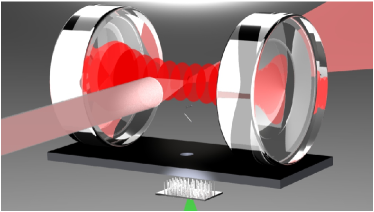
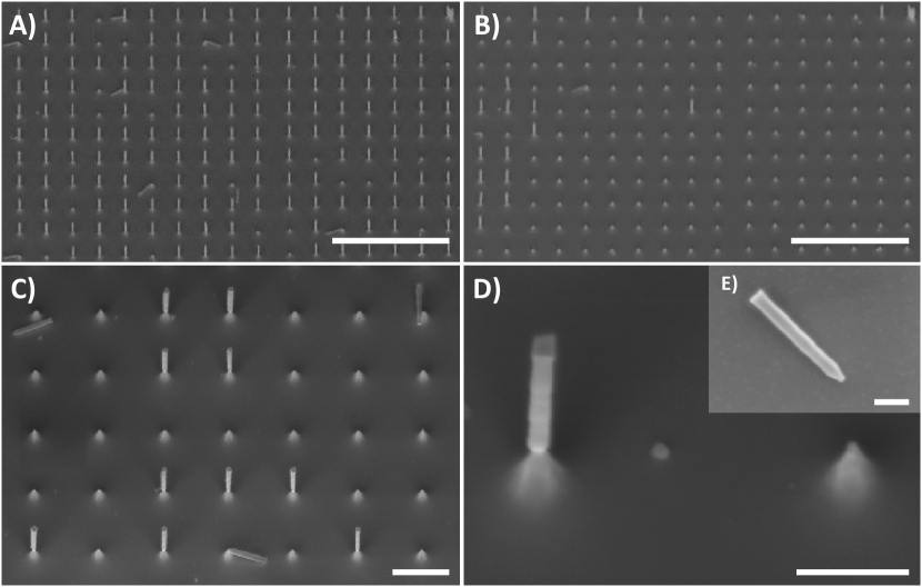
We have prepared periodic arrays consisting of more than a million silicon nanorods per mm2 by dry-etching crystalline silicon wafers (see Appendix.1). A scanning electron microscopy image of such an array is displayed in Figure 2A. The individual nanorods exhibit a length of nm and a diameter of nm corresponding to a mass of amu. The sample was positioned in a chamber evacuated to Pa underneath an optical cavity (see Figure 1). The backside of the sample was locally heated by a pulsed laser beam focused to m, which desorbs the rods by laser-induced thermomechanical stress (LITHMOS)Asenbaum et al. (2013). Small kerfs etched into the nanorod base define the desired break-off conditions (see Figure 2C & D; details in Appendix.1). In Figure 2A and B we show an electron micrograph of a sample spot before and after the LITHMOS pulses. It demonstrates that the rods can be reproducibly broken off at the tailored constrictions. Figure 2E depicts a close-up of the etched conical tip of a rod after launch and recapture.
The standing light wave field of a high-finesse cavity allows us to track the translational and rotational motion of the particles. It is optically pumped by a linearly polarized, distributed-feedback laser locked close to the cavity resonance. At the laser wavelength of 1560 nm silicon exhibits a high relative permittivity and minimal absorption. In a homogeneous field, the polarisability assumes a maximum value of Å3 and a minimum value of Å3 when the rods are oriented parallel and perpendicular to the field, respectively Hulst and Van De Hulst (1957). Even for rotating rods, the polarizability averaged over all possible rotation axes, Å3, is larger than for a silicon nanosphere of the same mass, Å3.
We can trace each nanorotor using the light it scatters into the direction perpendicular to both the cavity axis and the field polarisation. We collect this light in a 1 mm multimode fiber placed at a distance of 200 m from the cavity center. The detected intensity depends on the rod’s position in the standing wave and also on its orientation (see Appendix.2).
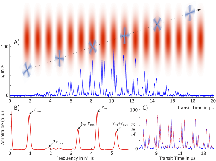
When a symmetric rotor enters the cavity and moves freely along the cavity axis, we expect a modulation of the scattering signal at two distinct frequencies: One is the translational frequency of the particle passing the standing-wave nodes with velocity , the second one is twice the rotation frequency, .
Figure 3A displays the normalized scattering intensity of a freely rotating nanorod, , where is the measured scattering signal and the simultaneously recorded intra-cavity intensity. Panel C shows that it agrees well with the theoretical expectations for light scattering at dielectric needles, see Appendix.2. We provide a full comparison of the measured signal in panel A and theory in Appendix.3 Figure S1. The corresponding Fourier spectrum, depicted in panel B, exhibits the distinct frequency contributions of translation and rotation.
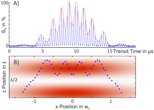
For slow rods we could observe cavity-induced translational channelling, i.e. one-dimensional trapping along an anti-node of the standing light wave. One such case is displayed in Figure 4, where the scattering signal (panel A) differs significantly from Figure 3. When averaged over the rotational period of the rod, the scattering signal (red dotted curve) does not drop to zero while the particle is close to the center of the Gaussian beam. During this time the frequency related to the transverse motion of the rod is influenced significantly. In panel B we reconstruct the particle trajectory through the cavity mode from the time evolution of the light scattering curve Asenbaum et al. (2013). This is reproduced in a simulation of the rod’s motion under the influence of the cavity field (see Appendix.3 Figure S2).
The optical channelling effect benefits from the geometrically enhanced induced dipole moment, due to the strong anisotropy of the rods Hulst and Van De Hulst (1957). For silicon nanorods rotating in the plane perpendicular to the cavity axis the orientation-averaged polarizability in the light field, , is enhanced by a factor of 2.7 in comparison to silicon spheres of the same mass. In Figure 4 we observe an enhancement of the trapping potential by a factor of 2.6.
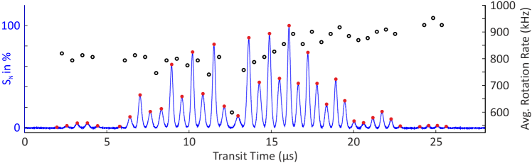
In addition to the optical force on the particle’s center of mass, the cavity field exerts a torque on the rods, which tends to align them along the field polarisation axis Bishop et al. (2003). Figure 5 displays the scattering curve of a slowly rotating nanorod manipulated in both its center-of-mass motion and its rotation. In analogy to Figure 4, we observe transverse channelling, but the rotation rate (black circles) is now influenced significantly by the optical torque. This indicates that the motional and rotational degrees of freedom exchange energy via the optical potential. The influence of the optical potential on the rotation rate is most pronounced at around 12 s.
In conclusion, we have presented a method to tailor, launch, track, and manipulate high-mass silicon nanorods with well-defined geometry and high aspect ratio. Light scattering inside a high-finesse infrared cavity allows us to follow the translational and rotational motion of the nanorotors in real time. For some of the rods, cavity assisted 1d-trapping and even rotational forces could be demonstrated. Our results are in good agreement with theoretical expectations and show that the rod-like shape enhances the interaction between the particles and the cavity field significantly, compared to silicon nanospheres of the same mass. Optomechanical trapping and cooling of the center-of-mass motion Li et al. (2011); Gieseler et al. (2012); Kiesel et al. (2013); Asenbaum et al. (2013); Bateman et al. (2014); Millen et al. (2015) will benefit from aligning the rods along the axis of polarisation. Recent studies on single particle thermodynamics Gieseler et al. (2013, 2014); Millen et al. (2014) may be extended to rotating systems. Our results represent a first step towards realizing torsional nano-optomechanics Shi and Bhattacharya (2013); Yin et al. (2013); Müller et al. (2015) and rotational cooling, which may become applicable to delicate biological nanomaterials such as the similarly shaped tobacco mosaic virus Ashkin and Dziedzic (1987); Romero-Isart et al. (2010).
Appendix
.1 Nanorod sculpting
The silicon nanorod arrays were fabricated from a single crystalline Si wafer by adapting a previously described dry etching method Pevzner et al. (2010). The 380 m thick, 100 cut and p-doped wafers exhibit a resistivity of 1-10 cm. They were cleaned by sonication, first in acetone then in isopropyl alcohol (IPA), each for 5 min. They were then thoroughly rinsed with deionized water and dried in a stream of N2. The clean Si wafers were spin coated with MMA resist (Copolymer resist EL9, MicroChem) at 4000 rpm for 60 s, followed by baking at 180∘C on a hotplate for 2 min. PMMA resist (Polymer resist A2, MicroChem) was deposited on the MMA layer by spinning at 2000 rpm for 60 s, followed by baking at 180∘C on a hotplate for 2 min.
An array of 250 nm diameter circular dots with 1 m spacing was written using a Raith 150 ultrahigh-resolution e-beam lithography system (Raith GmbH, Dortmund, Germany). The patterned wafer was developed in MIBK/IPA 1:3 for 1 min, followed by rinsing with IPA for 20 s and drying in an N2 stream. A nickel dot array was prepared by e-beam evaporating a 100 nm thick nickel layer at a base pressure of Torr with a rate of 1 Å/s. Finally, the remaining resist was lifted-off in an Acetone/IPA 1:1 solution, washed with IPA and dried. The nickel nanodot arrays served as masks in the following dry etching.
Vertical silicon nanowire arrays were fabricated by applying time-multiplexed reactive ion etching in an Inductively Coupled Plasma Deep Reactive Ion Etching machine (ICP-DRIE, PlasmaTherm SLR 770). In order to form nanopillars with a well defined breaking point, we have implemented a Bosch process, i.e. passivation followed by anisotropic etching. A variation of the ratio between the etching and the passivation times varies the scalloping and leads to different rod diameters. Based on that we set up a three-stage etching process: Six ’passivation-etching’ sequences with a time ratio of 1:1 allowed us to form 700 nm long nanorod segments. In order to create the breaking points, the ratio of the time windows was logarithmically changed to 0.7:1 during four further steps. Finally, a wider base was formed by changing the interval ratio linearly to 2:1 in six further steps. The silicon rods were cleaned by removing the nickel caps chemically.
.2 Scattering theory
In order to compute the normalized scattered light intensity , the rods are modelled as thin, homogeneous, dielectric needles of length and diameter . Adopting the scattering theory for dielectric needles Schiffer and Thielheim (1979) to a standing-wave situation, we find that the light intensity in the direction perpendicular to both the cavity axis and the field polarisation axis is proportional to
with the wave number, the cavity waist, and . Here, we denote the center-of-mass position of the rod by , and the orientation of the rod is determined by the radial unit vector . The internal field points in the direction .
.3 Simulation
Figures S1, S2 and S3 display the simulated dynamics of a nm long and nm thick silicon rod with mass and moment of inertia , which rotates in the plane perpendicular to the cavity -axis. In this case the rod can be treated as a sub-wavelength particle at position , and its orientation with respect to the field polarization -axis is described by . Given a constant intra-cavity field amplitude , the rod’s motion is governed by the following classical equations of motion:
with the cavity waist, the vertical velocity of the rod, and the polarizability components, as given in the main text. Particle trajectories that do not pass through the cavity center, but slightly off-axis, can be accounted for by decreasing the field amplitude below the cavity value . The corresponding scattering intensity is obtained by evaluating the expression given in Appendix .2 along the simulated trajectory. Since the scattering signal is here proportional to , the center-of-mass trajectory of a freely rotating rod can be reconstructed from the measured scattering signal by averaging over the fast rotation period. We ensure that we capture the full transit through the cavity mode by carrying out each simulation over the time interval between . In order to compare this to the measured data, the scattering signal must be normalized, and the time offset of the simulation must be adjusted, accordingly.
![[Uncaptioned image]](/html/1506.04881/assets/x6.png)
![[Uncaptioned image]](/html/1506.04881/assets/x7.png)
![[Uncaptioned image]](/html/1506.04881/assets/x8.png)
Acknowledgements
Our work has been supported by the European Commission (304886) as well as by the Austrian Science Fund (FWF): W1210-3 and P27297. We acknowledge support by S. Puchegger and the faculty center for nanostructure research at the University of Vienna in imaging the nanorods. F.P. acknowledges the Legacy Program (Israel Science Foundation) for its support.
References
- Krahne et al. (2013) Krahne, R.; Manna, L.; Morello, G.; Figuerola, A.; George, C.; Deka, S. Physical Properties of Nanorods; Springer, 2013.
- Hornberger et al. (2012) Hornberger, K.; Gerlich, S.; Haslinger, P.; Nimmrichter, S.; Arndt, M. Colloquium: Quantum interference of clusters and molecules. Rev. Mod. Phys. 2012, 84, 157–173.
- Arndt and Hornberger (2014) Arndt, M.; Hornberger, K. Insight review: Testing the limits of quantum mechanical superpositions. Nature Phys. 2014, 10, 271–277.
- Bateman et al. (2014) Bateman, J.; Nimmrichter, S.; Hornberger, K.; Ulbricht, H. Near-field interferometry of a free-falling nanoparticle from a point-like source. Nat. Commun. 2014, 5, 4788.
- Arndt et al. (1999) Arndt, M.; Nairz, O.; Vos-Andreae, J.; Keller, C.; van der Zouw, G.; Zeilinger, A. Wave-particle duality of C60 molecules. Nature 1999, 401, 680–682.
- Eibenberger et al. (2013) Eibenberger, S.; Gerlich, S.; Arndt, M.; Mayor, M.; Tüxen, J. Matter-wave interference with particles selected from a molecular library with masses exceeding 10 000 amu. Phys. Chem. Chem. Phys. 2013,
- Haslinger et al. (2013) Haslinger, P.; Dörre, N.; Geyer, P.; Rodewald, J.; Nimmrichter, S.; Arndt, M. A universal matter-wave interferometer with optical ionization gratings in the time domain. Nature Phys. 2013, 9, 144 – 148.
- Bassi et al. (2013) Bassi, A.; Lochan, K.; Satin, S.; Singh, T. P.; Ulbricht, H. Models of wave-function collapse, underlying theories, and experimental tests. Rev. Mod. Phys. 2013, 85, 471–527.
- Diosi (1987) Diosi, L. A universal master equation for the gravitational violation of quantum mechanics. Physics letters A 1987, 120, 377–381.
- Penrose (1996) Penrose, R. On gravity’s role in quantum state reduction. Gen. Rel. Grav. 1996, 28, 581–600.
- Li et al. (2011) Li, T.; Kheifets, S.; Raizen, M. G. Millikelvin cooling of an optically trapped microsphere in vacuum. Nature Phys. 2011, 7, 527 – 530.
- Gieseler et al. (2012) Gieseler, J.; Deutsch, B.; Quidant, R.; Novotny, L. Subkelvin Parametric Feedback Cooling of a Laser-Trapped Nanoparticle. Phys. Rev. Lett. 2012, 109, 103603.
- Kiesel et al. (2013) Kiesel, N.; Blaser, F.; Delic, U.; Grass, D.; Kaltenbaek, R.; Aspelmeyer, M. Cavity cooling of an optically levitated nanoparticle. Proc. Natl. Acad. Sci. USA 2013, 110, 14180 – 14185.
- Millen et al. (2015) Millen, J.; Fonseca, P. Z. G.; Mavrogordatos, T.; Monteiro, T. S.; Barker, P. F. Cavity Cooling a Single Charged Levitated Nanosphere. Phys. Rev. Lett. 2015, 123602, 1–5.
- Asenbaum et al. (2013) Asenbaum, P.; Kuhn, S.; Nimmrichter, S.; Sezer, U.; Arndt, M. Cavity cooling of free silicon nanoparticles in high-vacuum. Nat. Commun. 2013, 4, 2743.
- Shi and Bhattacharya (2013) Shi, H.; Bhattacharya, M. Coupling a small torsional oscillator to large optical angular momentum. J. Mod. Opt. 2013, 60, 382–386.
- Yin et al. (2013) Yin, Z.; Geraci, A.; Li, T. Optomechanics of levitated dielectric particles. Int. J. Mod. Phys. B 2013, 27, 1330018.
- Müller et al. (2015) Müller, T.; Reinhardt, C.; Sankey, J. C. Enhanced optomechanical levitation of minimally supported dielectrics. Physical Review A 2015, 91, 1–10.
- Bonin and Kourmanov (2002) Bonin, K. D.; Kourmanov, B. Light torque nanocontrol, nanomotors and nanorockers. Opt. Expr. 2002, 10.
- Paterson et al. (2001) Paterson, L.; MacDonald, M. P.; Arlt, J.; Sibbett, W.; Bryant, P. E.; Dholakia, K. Controlled rotation of optically trapped microscopic particles. Science 2001, 292, 912–4.
- Jones et al. (2009) Jones, P. H.; Palmisano, F.; Bonaccorso, F.; Gucciardi, P. G.; Calogero, G.; Ferrari, A. C.; Marago, O. M. Rotation Detection in Light-Driven Nanorotors. ACS Nano 2009, 3, 3077–3084.
- Tong et al. (2010) Tong, L.; Miljkovic, V. D.; Kall, M. Alignment, rotation, and spinning of single plasmonic nanoparticles and nanowires using polarization dependent optical forces. Nano Lett. 2010, 10, 268–73.
- Marago et al. (2013) Marago, O. M.; Jones, P. H.; Gucciardi, P. G.; Volpe, G.; Ferrari, A. C. Optical trapping and manipulation of nanostructures. Nature Nanotech. 2013, 8, 807–19.
- Arita et al. (2013) Arita, Y.; Mazilu, M.; Dholakia, K. Laser-induced rotation and cooling of a trapped microgyroscope in vacuum. Nat. Commun. 2013, 4.
- Hulst and Van De Hulst (1957) Hulst, H.; Van De Hulst, H. Light scattering by small particles; Dover, 1957.
- Bishop et al. (2003) Bishop, A. I.; Nieminen, T. A.; Heckenberg, N. R.; Rubinsztein-Dunlop, H. Optical application and measurement of torque on microparticles of isotropic nonabsorbing material. Phys. Rev. A 2003, 68, 033802.
- Gieseler et al. (2013) Gieseler, J.; Novotny, L.; Quidant, R. Thermal nonlinearities in a nanomechanical oscillator. Nature Phys. 2013, 9, 806–810.
- Gieseler et al. (2014) Gieseler, J.; Quidant, R.; Dellago, C.; Novotny, L. Dynamic relaxation of a levitated nanoparticle from a non-equilibrium steady state. Nature Nanotech. 2014, 9, 358–64.
- Millen et al. (2014) Millen, J.; Deesuwan, T.; Barker, P.; Anders, J. Nanoscale temperature measurements using non-equilibrium Brownian dynamics of a levitated nanosphere. Nature Nanotech. 2014, 9, 425 – 429.
- Ashkin and Dziedzic (1987) Ashkin, A.; Dziedzic, J. M. Optical trapping and manipulation of viruses and bacteria. Science 1987, 235, 1517–1520.
- Romero-Isart et al. (2010) Romero-Isart, O.; Juan, M.; Quidant, R.; Cirac, J. Toward quantum superposition of living organisms. New J. Phys. 2010, 12, 033015.
- Pevzner et al. (2010) Pevzner, A.; Engel, Y.; Elnathan, R.; Ducobni, T.; Ben-Ishai, M.; Reddy, K.; Shpaisman, N.; Tsukernik, A.; Oksman, M.; Patolsky, F. Knocking down highly-ordered large-scale nanowire arrays. Nano Letters 2010, 10, 1202–1208.
- Schiffer and Thielheim (1979) Schiffer, R.; Thielheim, K. Light scattering by dielectric needles and disks. J. Appl. Phys. 1979, 50, 2476–2483.