On Carbon Burning in Super Asymptotic Giant Branch Stars
Abstract
We explore the detailed and broad properties of carbon burning in Super Asymptotic Giant Branch (SAGB) stars with 2755 MESA stellar evolution models. The location of first carbon ignition, quenching location of the carbon burning flames and flashes, angular frequency of the carbon core, and carbon core mass are studied as a function of the ZAMS mass, initial rotation rate, and mixing parameters such as convective overshoot, semiconvection, thermohaline and angular momentum transport. In general terms, we find these properties of carbon burning in SAGB models are not a strong function of the initial rotation profile, but are a sensitive function of the overshoot parameter. We quasi-analytically derive an approximate ignition density, g cm-3, to predict the location of first carbon ignition in models that ignite carbon off-center. We also find that overshoot moves the ZAMS mass boundaries where off-center carbon ignition occurs at a nearly uniform rate of / 1.6 . For zero overshoot, =0.0, our models in the ZAMS mass range 8.9 to 11 show off-center carbon ignition. For canonical amounts of overshooting, =0.016, the off-center carbon ignition range shifts to 7.2 to 8.8 . Only systems with and ZAMS mass 7.2-8.0 show carbon burning is quenched a significant distance from the center. These results suggest a careful assessment of overshoot modeling approximations on claims that carbon burning quenches an appreciable distance from the center of the carbon core.
Subject headings:
stars: evolution — stars: interiors — stars: rotation — supernovae: general1. Introduction
When a single star on the main sequence (MS) exhausts the supply of hydrogen in its core, the core contracts and its temperature increases, while the outer layers of the star expand and cool. The star becomes a red giant (e.g., Iben, 1991; Stancliffe et al., 2009; Karakas & Lattanzio, 2014). The subsequent onset of helium burning in the core causes the star to populate the horizontal branch for more metal-poor stars or the red clump for more metal-rich stars (Cannon, 1970; Faulkner & Cannon, 1973; Seidel et al., 1987; Castellani et al., 1992; Girardi, 1999). After the star exhausts the supply of helium in its core, the carbon-oxygen (henceforth CO) core contracts while the envelope once again expands and cools along a path that is aligned with its previous red-giant track. The star becomes an asymptotic giant branch (AGB) star (e.g., Hansen et al., 2004; Herwig, 2005; Kippenhahn et al., 2012; Salaris et al., 2014; Fishlock et al., 2014).
The minimum mass for carbon ignition is usually referred to as M 7 and the minimum mass for neon ignition in the core is traditionally referred to as M 10 (Becker & Iben, 1979, 1980; García-Berro et al., 1997). Stars with zero age main-sequence (ZAMS) masses between 7 M⊙ and 10 are designated as super-AGB stars (henceforth SAGB, Ritossa et al., 1996, 1999; Gil-Pons et al., 2005; Siess, 2006, 2007, 2010; Poelarends et al., 2008; Doherty et al., 2010). Due to the inferred slope of the stellar initial mass function from observations (e.g., Jennings et al., 2012), single stars in this ZAMS mass range represent the population of stars that can produce the most massive white dwarfs, the most numerous supernovae and possibly the least massive neutron stars (e.g., Doherty et al., 2015). SAGB stars may also make significant contributions to the Galactic inventory of isotopes such as 7Li, 14N, 23Na, 25-26Mg, 26-27Al and 60Fe (Siess, 2010; Ventura et al., 2013; Doherty et al., 2014a, b).
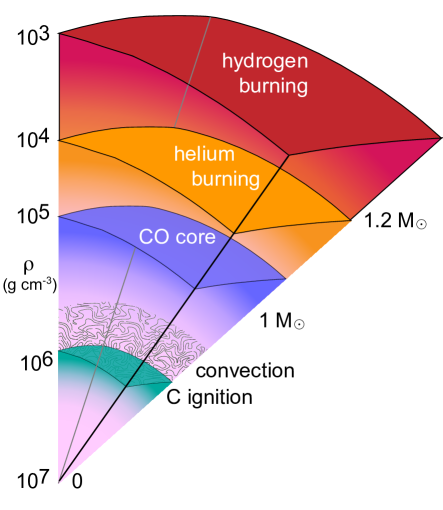
After helium is exhausted in the core, stars ascending the SAGB develop partially electron degenerate carbon–oxygen cores ranging from 0.9 to 2.0 (pioneering studies of CO cores include Rakavy et al., 1967; Beaudet & Salpeter, 1969; Boozer et al., 1973). Depending primarily on the ZAMS mass but also sensitively on the composition mixing model (Poelarends et al., 2008; Siess, 2009), the ignition of carbon may not occur at all (for stars 7 ), occur at the center of the star (for stars 10 ), or occur somewhere off-center. In the off-center case, ignition is followed by the inward propagation of a subsonic burning front (Nomoto & Iben, 1985; Timmes et al., 1994; García-Berro et al., 1997; Saio & Nomoto, 1998). Trailing behind the burning front is a convective region that may extend outward 0.6 ; see Figure 1 for an illustration. When a steady-state, convectively bounded, subsonic, carbon burning front (henceforth a “flame”) propagates toward the center of the CO core, the flame leaves behind oxygen-neon-magnesium (ONeNa) ashes. The inward propagating carbon flame may or may not reach the center of the star, depending on the parameters adopted for composition mixing beyond the convective boundary set by mixing-length theory (e.g., thermohaline, overshoot, semi-convection, Siess, 2009; Stancliffe et al., 2009; Denissenkov et al., 2013). If the flame makes it to the center, then the original CO core is converted into an ONeNa core. Such SAGB stars can explode as electron capture supernovae if their ONeNa core masses reach central densities in excess of the threshold density for the 20Ne(e-,)20F electron capture reaction (Miyaji et al., 1980; Nomoto, 1984; Gutierrez et al., 1996; Jones et al., 2013), as may be the case for the Crab Nebula (Davidson et al., 1982; Nomoto et al., 1982; Wanajo et al., 2009) or for potentially explaining observations of sub-luminous type II-P supernovae (Smartt, 2009). If the flame does not make it to the center, then the star is left with inner parts of the original CO core surrounded by a layer of ONeNa. Such hybrid white dwarfs may provide unusual Type Ia supernovae progenitors (Siess, 2009; Denissenkov et al., 2013; Wang et al., 2014; Chen et al., 2014).
This paper explores the ignition and subsequent evolution of carbon burning in SAGB stellar models as a function of the ZAMS mass, initial rotation rate, the magnitude of various mixing parameters such as convective overshoot, semiconvection, thermohaline and angular momentum transport. We sample this multi-dimensional space with 2,755 MESA stellar evolution models (Paxton et al., 2011, 2013) that are evolved from the pre-main-sequence to the end of carbon burning. All models have and a solar composition from Grevesse & Sauval (1998). Along the way we provide quasi-analytic models for interpreting the results. In § 2 we discuss the input physics for our calculations, the composition mixing processes considered, and the MESA implementation of rotation and magnetic fields. In § 3 we define the baseline parameters used for our calculations and discuss the grids used for our exploration into this three dimensional parameter space. In § 4 we present the results of our non-rotating models, an analytical approximation of the location of first carbon ignition, and the evolution of carbon burning flames and flashes. In § 5 we present the results of the effect of rotation and overshoot on the ignition, evolution, and death of carbon burning. In § 6 we study the impact of the semiconvection, thermohaline, and angular momentum transport coefficients on the location of first carbon ignition on our results. In § 7 we present the results of spatial and temporal convergence studies on our results, and in § 8 we discuss our results and their implications.
2. Instrument and Methods
Our numerical instrument is MESA version 6794. We use the included sagbNeNaMgAl.net reaction network, which follows 22 isotopes from 1H to 27Al to track hydrogen (pp chains, CNO-, NeNa-, and MgAl-cycles), helium and carbon burning. The 51 thermonuclear reaction rates coupling these isotopes are from JINA reaclib version V2.0 2013-04-02 (Cyburt et al., 2010), energy-loss rates and their derivatives from thermal neutrinos are from the fitting formulae of Itoh et al. (1996), and electron screening factors for thermonuclear reactions in both the weak and strong regimes are from Dewitt et al. (1973); Graboske et al. (1973) and Alastuey & Jancovici (1978) with plasma parameters from Itoh et al. (1979). Poelarends et al. (2008) showed that increasing the mass loss rate could decrease the mass range for systems that will become electron capture supernovae (ECSNe). We thus use a Reimer mass loss prescription (Reimers, 1975) with =0.5 on the RGB and a Blöcker mass loss prescription (Bloecker, 1995) with =0.05 on the AGB. The MESA inlists are publicly available111http://mesastar.org/results.
Analysis of a carbon burning event requires knowledge of when and where carbon ignites. We identify the cell location of carbon burning, hence the ignition mass coordinate (), by three criteria. First, we require in a CO core. Second, we require that 4He is depleted in the ignition region as some of the lowest mass stars investigated would have a small amount of 12C burning near the CO core, 4He shell boundary. Finally, we require X(, which indicates we have vigorous 12C +12C burning.
The end of a carbon burning event is defined when no cell within 10% of the mass location of the flame, during the next time step, has . We then define the final flame location (), where carbon burning is quenched, as the minimum value of the mass location taken at the end of all the carbon burning events. This is independent of any subsequent carbon flashes, as we record only the closest approach the carbon burning makes to the core.
2.1. Mixing
Treatment of convective processes within stellar interiors is essential for a physically accurate stellar model. We briefly discuss the composition mixing processes used in our calculations, how MESA models the mixing processes, and previous studies that guide our choices for our baseline mixing parameters. Values for our baseline parameters are given in 3.
We use the Schwarzschild criterion for convection along with the Cox implementation of Mixing Length Theory (MLT) (Cox & Giuli, 1968). The Schwarzschild criterion describes that a region is stable to convection if the gradient of a piece of adiabatic matter is less than that of the temperature gradient of the stellar atmosphere:
| (1) |
MLT has a free parameter, , as described by Böhm-Vitense (1958). Values within have been inferred by Noels et al. (1991) who compared observations of the Centauri binary star system with stellar evolution models. Trampedach et al. (2014) also suggests from calibrating 1D stellar models to 3D radiation-coupled hydrodynamics simulations of convection in stellar surface layers.
Turbulent velocity fields have been suggested to decay exponentially beyond the Schwarzschild convective boundary defined by equation 1 (Herwig et al., 1997; Ventura et al., 1998; Mazzitelli et al., 1999; Blöcker et al., 2000; Herwig, 2000) leading to a diffusive treatment of mixing as
| (2) |
Here is the convective diffusion coefficient at the convective boundary, is the radial distance from the convective boundary, is the local pressure scale height and is an adjustable parameter. MESA offers the flexibility of allowing to be different for different convective regions (H burning, He burning, metal burning and non burning). However, we set to the same value in all convective regions (see §3 for the values chosen).
Semiconvection occurs when regions of the stellar interior are stable to the Ledoux criterion and unstable to the Schwarzschild criterion (Kippenhahn et al., 2012). This occurs when , where and is the Brunt composition gradient. MESA treats semiconvection as a diffusive process (Langer et al., 1983, 1985; Heger et al., 2000; Zaussinger & Spruit, 2013) with a diffusion coefficient
| (3) |
where is the radiative conductivity, is the specific heat at constant pressure and is an adjustable dimensionless parameter describing the speed with which convective mixing may occur at the boundary defined by equation 1. Ongoing efforts to calibrate such semiconvection models include multidimensional numerical simulations of double-diffusive convection (Zaussinger & Spruit, 2013; Spruit, 2013) and comparing massive star models with observations (Yoon et al., 2006).
Thermohaline mixing occurs when . These are regions stable against convection, according to the Ledoux criterion, but have an inversion of the mean molecular weight (Kippenhahn et al., 1980). This type mixing forms elongated fluid parcels, sometimes called “salt-fingers”. MESA treats thermohaline mixing as a diffusion process (Ulrich, 1972; Kippenhahn et al., 1980; Brown et al., 2013; Zemskova et al., 2014)
| (4) |
where is a dimensionless parameter, related to the aspect ratio of the salt fingers. Estimates for this parameter range from (Kippenhahn et al., 1980; Charbonnel & Zahn, 2007; Cantiello & Langer, 2010; Stancliffe, 2010; Wachlin et al., 2011), with some multidimensional simulations suggesting this parameter is significantly overestimated (Denissenkov, 2010; Traxler et al., 2011; Denissenkov & Merryfield, 2011; Lattanzio et al., 2015).
2.2. Rotation and Magnetic Fields
MESA implements rotation by making the assumption that the angular velocity, , is constant over isobars; see Paxton et al. (2013) for the implementation of rotation into MESA. Such an assumption is often referred to as shellular approximation (Zahn, 1992; Meynet & Maeder, 1997), and allows the stellar structure equations to be solved in one dimension for a rotating star. For this study, rotation is initialized by imposing a solid body rotation law at ZAMS, where the total luminosity equals the nuclear burning luminosity.
The transport of angular momentum and material due to rotationally induced instabilities is followed using a diffusion approximation (e.g., Endal & Sofia, 1978; Pinsonneault et al., 1989; Heger et al., 2000; Maeder & Meynet, 2003, 2004; Heger et al., 2005; Suijs et al., 2008) for the dynamical shear instability (DSI), secular shear instability (SSI), Eddington-Sweet circulation (ES), Goldreich-Schubert-Fricke instability (GSF), and Spruit-Tayler dynamo (ST). See Heger et al. (2000) for a description of the physics of the different instabilities and the calculation of the respective diffusion coefficients.
Berger et al. (2005) investigated the Ca line profiles of a sample of DA white dwarfs, concluding their rotational velocities are generally less than 10 km s-1. These values are significantly less than the values determined by the rotating, nonmagnetic models of Langer et al. (1999). Internal magnetic torques as proposed by Spruit (1998) have been suggested as an effective mechanism to spin down the cores of these white dwarf progenitors during the giant phase. Suijs et al. (2008) showed that magnetic torques as calculated in Spruit (2002) produce rotational velocities in better agreement with the observed values of Berger et al. (2005). We therefore include internal magnetic fields and the Spruit Tayler dynamo angular momentum mechanism for our rotating MESA models.
Magnetic fields are implemented in MESA using the formalism of Heger et al. (2005), where a magnetic torque due to a dynamo (Spruit, 2002) allows angular momentum to be transported inside the star. The radial component, , and the azimuthal component, , of the magnetic field are modeled as
| (5) |
| (6) |
where is the radial coordinate, the density, the Alfvén frequency, and the wavenumber. These magnetic fields then provide a torque
| (7) |
which acts to slow down the stars rotation rate by decreasing the amount of differential rotation inside the star (Heger et al., 2005).
The initial rotation is normalized against the critical rotation rate for the star , where c the speed of light, the mass of the star, the stellar radius, the luminosity and the Eddington luminosity. The initial magnetic field, for all our rotating models. Effects of rotationally induced mass loss are not included.
3. Grids
We define a set of baseline parameters and construct a number of grids surrounding that baseline set to investigate the sensitivity of carbon burning in the SAGB models with respect to variation in the baseline parameters. Choices in the numerical values of the baseline parameters are based on the current understanding of the canonical values for SAGB and other stars when using MESA. Choices in the range of values explored were designed such that we could explore the various competing factors involved in stellar evolution models.
Table 1 lists the baseline mixing, spatial resolution, and temporal resolution parameters. The parameter is the ratio of turbulent viscosity to the diffusion coefficient (Heger et al., 2000), is the sensitivity to -gradients (Heger et al., 2000), while controls the spatial resolution by determining the relative magnitude of changes between the adjacent cells (Paxton et al., 2011), and controls the temporal resolution by modulating the magnitude of the allowed changes between time steps (Paxton et al., 2011). Baseline values for and were based on computational requirements. However see § 7 for a discussion into their relative effects on our results. The other baseline parameters listed in Table 1 are discussed in §2.1.
3.1. Mass-Rotation-Overshoot Grid
We explore the (ZAMS mass, initial rotation, overshoot) parameter space with three slices through this 3D data cube. Table 2 lists the start, stop, and step values for two of the three quantities while holding the third quantity constant. The number of SAGB models is 1326 in the mass-rotation plane, 546 in the rotation-overshoot plane, and 546 in the mass-overshoot plane for a total of 2418 SAGB models. Figure 2 illustrates these three orthogonal slices though this 3D parameter space.
For each slice within the 3D data cube we chose one quantity to be held fixed. In the mass-rotation plane this is the overshoot value, and our choice of =0.016 is based on the canonical value for this overshoot model (Herwig, 2000). In the rotation-overshoot plane we held the initial mass fixed at , which was selected because, based on the non-rotating models, we expected we could induce a range of behaviors from non-ignition, to off-center ignition to central ignition. In the mass-overshoot plane, we held the initial rotation fixed at =0.25, purely as a middle ground value between non-rotating models and our upper bound of =0.5. Our choice for the range of values covered by each grid was based on a requirement to have a comprehensive sample over the canonical baseline values for SAGB stars.
h Parameter Value Mixing Length Theory () Semiconvection () Thermohaline () 1.0000 Overshoot () Angular Momentum () Turbulent Viscosity () 0.0333 -gradient Sensitivity () 0.0500 Mesh Delta Coefficient () 0.5000 Variance Control Target () 0.0001
h Variable Start Stop Step Constant 6.0 11.0 0.1 =0.016 0.0 0.5 0.02 0.0 0.5 0.02 =8.0 0.0 0.02 0.001 6.0 11.0 0.2 = 0.25 0.0 0.02 0.001
h Variable Values 0.0 10-3 10-2 10-1 0.0 0.1 1.0 10.0 0.000 0.001 0.016 0.020 0.0 0.5 1.0 1.5
h Variable Values 7 8 9 0.0 0.25 0.5 0.1 0.5 1.0 10-5 10-4 10-3
3.2. Mixing Coefficients Grid
We investigate the (semiconvection, thermohaline, overshoot, angular momentum diffusion) parameter space on the location of the first carbon ignition in a 8 ZAMS, =0.25 model with selected points in this 4D data cube. Table 3 lists these quantities and their selected values. We choose to limit the range of in this grid to span only the lower values discussed in the literature. is a scale factor that alters the strength of angular momentum diffusion in each cell; see Paxton et al. (2013) for details. The total number of SAGB models in this grid is 44=256. This grid permits assessment of the relative strengths of each mixing process.
3.3. Spatial and Temporal Convergence Grid
Finally, we examine the spatial and temporal convergence properties of a subset of our SAGB models. The MESA parameter broadly controls the spatial resolution and broadly relates to the temporal resolution. For =0.5 there are 5,00010,000 spatial points center to surface. Spatial resolutions necessary to capture carbon burning flames and flashes are discussed in §7. For a temporal resolution of 10 yrs is achieved. Table 4 lists these quantities and their values. The total number of SAGB models in this resolution sensitivity grid is 34=81.
4. Results From Non-Rotating Models with Baseline Mixing Parameters
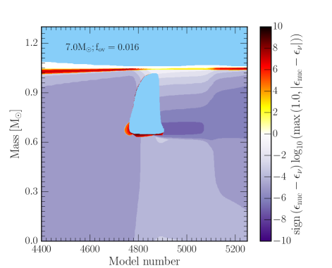
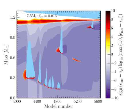
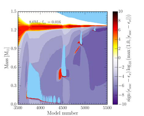
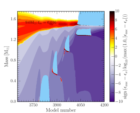
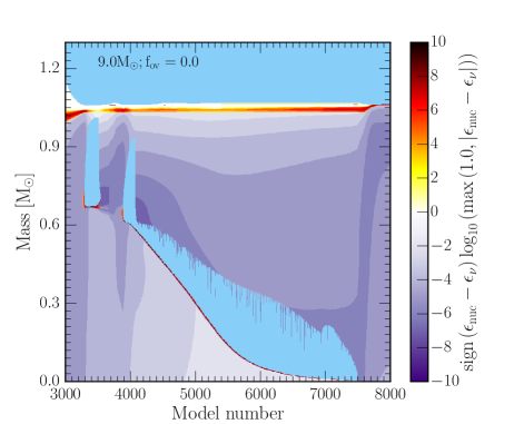
We begin by considering a series of non-rotating stellar models using our baseline mixing parameters as described in § 2. Figure 3 shows the Kippenhahn plots of these non-rotating stars as representative samples for all the stellar models. In the 7 case, carbon ignites off-center at 0.6 . However, it rapidly quenches and does not propagate towards the core. The 7.5 case undergoes a series of carbon flashes, with each flash igniting closer to the core but it is unable to form a steady state flame. In the 8 case, an off-center ignition occurs at 0.15 . A flame propagates inwards and through a series of distinct flashes as the flame approaches the core, and almost reaches the center. For the 9 case, carbon ignites at the center. In both the 8 and 9 models, secondary flashes at 0.5 are due to off-center carbon burning. For all cases the core is undergoing significant cooling, primarily through photo-neutrino and plasma neutrino losses prior to the first ignition of carbon (Nomoto, 1984, 1987; Ritossa et al., 1996, 1999). The 7.5, 8.0 and 9.0 cases the stars undergo a series of subsequent carbon flashes that travel away from the core. For the 9.0 case with no overshoot (bottom right in Figure 3) the flame ignites off-center, contrary to the center ignition of the 9 model with . The star undergoes a flash and then a flame, which propagates all the way to the center. The model with closest morphology is the 8 case which has a flash and flame, but carbon burning does not reach the center. The difference between models with overshoot and without will be discussed further in §6.
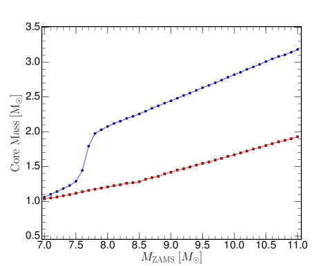
The He and CO core masses for the non-rotating models are shown in Figure 4 as a function of the ZAMS mass. Stellar models with MZAMS 7 do not ignite carbon (Becker & Iben, 1979, 1980) and are not shown. The carbon core mass increases linearly with ZAMS mass over the range shown. For M 7.5 , the He forms a radiative, geometrically thin, burning shell accreting material onto the CO core at a rate of 10. Between 7.5 and 8.0 , Figure 4 shows the He shell transitions from an geometrically thin shell to an geometrically thick shell. For M8.0 , the geometrically thick He shell mass grows linearly with ZAMS mass over the range shown, accreting material onto the CO core at 3 at 8.0 , and increasing to 2.0 for the stellar models.
As the star evolves, the He shell grows in mass reaching 1.7 for the 7 stars and up to 3.2 for the 11 stars. Once the He shell reaches its peak size, the 4He depletes quickly leaving a CO core. Shortly afterwards the 4He shell begins rapidly accreting material onto the CO core, eventually depleting itself as well. At the lowest ZAMS masses (), ignition occurs after the 4He shell has accreted onto the CO core and the star has finished its second dredge up (2DU) (Becker & Iben, 1979). In the transition region where we have a series of flashes (), the stars are undergoing their 2DU while igniting carbon. In the higher mass systems, 7.98.2 , where we have steady state flames or central carbon ignition, the star ignites carbon before the 2DU and before any significant accretion on to the CO core can occur. Above 8.3 we have dredge out events (Ritossa et al., 1999), where the 4He shell grows an an outwardly moving convection zone which merges with the inwardly moving convective envelope.
At the base of the flame, we can ask whether a packet of convective material can penetrate into the region ahead of the flame transferring energy which will decrease the flames lifetime. A simplified derivation (L. Bildsten, private communication) assumes the length scale of the flame front (the distance over which the temperature decreases from a peak inside the flame to the background value) is much less than the local pressure scale height, . This implies the pressure is constant across the subsonic flame front. A convective packet will move from a region of high temperature to a lower temperature region, at constant pressure. Assuming adiabatic motion, a fluid packet keeps its original temperature. Thus, the buoyancy felt by this convective packet is:
| (8) |
Where is the buoyancy acceleration, is the local acceleration due to gravity, and is the distance the packet moves ahead of the flame. Simplifying,
| (9) |
and solving this harmonic oscillator equation we find
| (10) |
where is the convective velocity and is the Brunt–Väisälä frequency. Using the local scale height , where is the local sound speed:
| (11) |
In a typical carbon flame we have and , thus and a convective fluid packet cannot penetrate the flame front.
4.1. First Ignition of Carbon
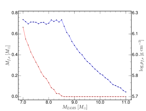
Figure 5 shows the mass location of the first ignition as a function of the stellar model ZAMS mass. For our choice of baseline mixing parameters, the lowest mass star to ignite carbon is a 7 model and ignition occurs off-center at a mass coordinate of 0.65 . As the ZAMS mass increases, the location of the off-center first ignition location moves steadily inwards in mass (Siess, 2007). For ZAMS masses larger than 8.4 , carbon ignites at the center. Figure 5 also shows the local density at the location of first ignition. All stellar models that ignite carbon off-center, 7 MZAMS 8.4 , do so at a nearly constant density of 6.2, or 1.5106 g cm-3. For stellar models that undergo central carbon ignition, 8.4 MZAMS 11 , the density at ignition monotonically decreases. Models which do not ignite carbon will eventually form a CO WD. Those models that undergo off-center carbon ignition but where the burning does not reach the center will form hybrid CO+ONe WD. Model stars which ignite carbon at the center will eventually form an ONeNa WD which may explode as an ECSNe.
To a first approximation, at ignition the nuclear burning timescale and thermal diffusion timescales are equal (Timmes & Woosley, 1992)
| (12) |
where is the thermal conductivity, is the specific heat capacity at constant pressure, is the local thermal energy, and is the screened nuclear energy generation rate during carbon burning including energy losses due to neutrino cooling. For a given temperature, density, and composition both and may be calculated from an equation of state. For carbon burning, takes the form (e.g., Woosley et al., 2004):
| (13) |
where X(12C) is the carbon mass fraction, is the density divided by 106 g cm-3, is the unscreened nuclear reaction rate for carbon burning and is the electron screening factor. Using a MESA 501 isotope reaction network that includes neutrino losses with an initial initial composition of X(12C) = 0.3 and X(16O) = 0.7 to calculate over the relevant range in the -T plane, we find positive values of may be approximated by the power law
| (14) |
Results for carbon ignition for any large reaction network, including the 501 isotope network used here, are expected to be similar to that of the smaller 22 isotope net used in the SAGB models because both networks have the same set of key isotopes and reaction rates crucial for carbon burning. (e.g., Timmes et al., 2000).
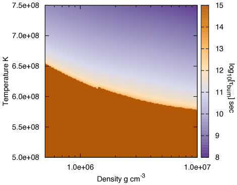
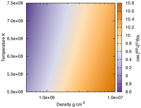
Fitting the other quantities in equation 12 in a similar manner, we find the following expressions for the nuclear burning timescale and thermal diffusion timescales
| (15) |
| (16) |
These two timescales are shown in Figure 6. Equating the two timescales gives
| (17) |
At the threshold of vigorous carbon burning, 7108 K, this expression gives a unique and constant ignition density
| (18) |
which is consistent with the constant ignition density of 1.5106 g cm-3 found in the MESA SAGB models that ignite carbon off-center, 7 MZAMS 8.4 , of Figure 5. We find this result also holds for our rotating SAGB models.
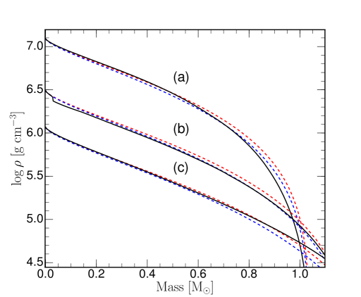
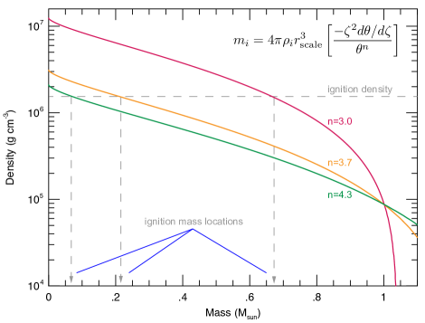
Figure 7 (a) shows the carbon core of a non-rotating 7 ZAMS star can be well approximated by a 3.0 polytropic model, (b) a 8 ZAMS star by a 3.7 polytrope, and (c) a 9 ZAMS star by a 4.3 polytrope. The density structures for these polytropic models were calculated using an open-source tool222http://cococubed.asu.edu/code_pages/polytrope.shtml. In addition, the polytropic relations offer an explanation for why the location of the first ignition moves steadily inwards in mass for the off-center ignition cases (see Figure 5). The density structure of the = 3.0, 3.7, and 4.3 polytrope models are shown in Figure 8. The mass locations for a fixed ignition density (dashed horizontal line), where ignition occurs (dash vertical lines) moves monotonically inwards as the polytropic index increases, as the carbon core mass increases, as the ZAMS mass increases.
We now turn to the decrease in the central density for those SAGB models in Figure 4 that centrally ignite carbon. Homology relations between the central density and the mass (e.g., Hansen et al., 2004; Kippenhahn et al., 2012) for a chemically homogeneous star characterized by a mean molecular weight , constant opacity, ideal gas equation of state and power-law energy generation rate indicate
| (19) |
For carbon burning near ignition, equation 14 shows 23, and equation 19 then gives M-1.5. The negative exponent shows that the density at first ignition, for those 8.4 MZAMS 11 models that undergo central carbon ignition, monotonically decreases as the mass of the carbon core increases with a slope that is consistent with the rate of decline shown in Figure 5.
4.2. Carbon Burning flashes and Transition to a Steady State Flame
Local characteristics before, during, and after the first off-center carbon flash in a 7.5 model is shown Figure 9. Before the first ignition of carbon, the CO core is in its most compact, most electron degenerate configuration. The first off-center carbon burning flash is thus the most powerful; any subsequent flashes or steady-state flames take place under more extended, less degenerate configurations. In addition, the energy released during the first ignition decreases as the ZAMS mass increases because the CO core is not as compact and not as degenerate. Furthermore, the first carbon flash impacts the base of the convective envelope more strongly in lower mass SAGB models than in higher mass SAGB models (García-Berro et al., 1997; Siess, 2006), partly because of their more compact configuration but also because the first flash occurs farther from the center in lower mass models (see Figure 5).
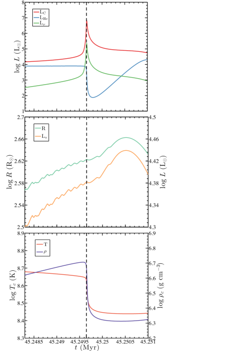
At the start of carbon burning at the ignition density of 1.5106 g cm-3, marked by the vertical dotted line in Figure 9, the energy generation rate rapidly rises. Figure 9 shows that 10% of the energy produced by nuclear reactions is lost to neutrinos, with the balance of the thermal energy transported by convection (Ritossa et al., 1996; Saio & Nomoto, 1998). This is not the 50% expected for steady state burning, as the 7.5 model is undergoing a time-dependent flash and not a steady state flame. Were it not for carbon burning, the surface luminosity and radius of these SAGB models would continue to increase in step with an increasing helium-burning luminosity, similar to lower mass, MZAMS 7 AGB stars that do not experience carbon burning (García-Berro et al., 1997; Karakas & Lattanzio, 2014). These dramatic events mainly impact the core and have only a modest effect on the structure of the outer envelope and surface luminosity.
Figure 9 shows the rapid injection of energy causes the entire core to expand and cool (Ritossa et al., 1999). A convective region also develops above the ignition location in response to the injection of energy from carbon burning. The overall expansion of the core decreases the electron degeneracy parameter ( means non-degenerate where is the electron chemical potential, means perfect degeneracy). The expansion extinguishes the flash partially because the nuclear energy generation rate drops below the critical luminosity (e.g., Siess, 2006) and partially because the ignition density is pushed deeper into the stellar model. The first flash thus quenches and does not become a steady-state flame that propagates inwards toward the center.
After the first flash is quenched and the deposition of energy from nuclear reactions ceases, the core again contracts but to a less compact, less degenerate configuration. This contraction leads to the second ignition of carbon. The second flash (and any subsequent flashes) occurs at a deeper mass coordinate because the accretion of C from the He burning shell slightly increases the core mass which moves the location of the critical density inwards where there is also fresh, previously unburned fuel. Similar evolution pathways can occur for other fuels and other masses, for example, neon burning in more massive models (e.g., Jones et al., 2013).
The evolution of the second and any subsequent flashes is notably different than the first flash as shown in Figure 3. When these later flashes develop, their convective region grows into regions previously occupied by previous flashes where carbon had been depleted. Thus the nuclear energy production rate, which from equation 13 is proportional to X2(12C), is reduced. Furthermore, the subsequent core expansion and induced thermodynamic changes are significantly smaller. The first flash lasts the longest and is the most vigorous, while subsequent flashes have shorter lifespans, release less energy, and the time interval between flashes becomes shorter Models which have a geometrically thin helium envelope show more flashes than models with a geometrically thick helium envelope (see Figure 4).
Each flash releases less energy, expands the core by a smaller amount, and moves the mass location of the critical density inward at a slower rate. This allows a flash to transition to a steady-state flame. Thus, after one or more flashes a steady-state may be achieved. Combustion in steady-state flames is incomplete; only a small portion of the carbon burns. A condition of balanced power is set up where the rate of energy emitted as neutrinos from the base of the convective region equals the power available from the unburned fuel that crosses the flame front. The inward propagation of the flame by thermal conduction is limited by the temperature at the base of the convective shell, which cannot greatly exceed the adiabatic value. These two local conditions give a unique speed for the flame, with typical values of 0.1 cm s-1. We verified the flame speed at several locations in the SAGB models and it is commensurate with previous local studies, with speeds of order cm s-1(e.g., Timmes et al., 1994; Ritossa et al., 1996; García-Berro et al., 1997; Siess, 2006; Denissenkov et al., 2013). The flame lives 20,000 years on its journey towards the center.
The convective nature of the material behind the flame has two key consequences for its journey to the core. First, the temperature behind the flame front (i.e., towards the surface) is bounded. The ONeNa ashes of the burning are not allowed to assume an arbitrary value of temperature; rather convection fixes the temperature behind the flame front. The second feature of the convective material is the lack of abundance gradients behind the flame. That is, convection uniformly mixes the ashes of the partial burning.
For our standard mixing parameter settings, models with ZAMS masses in the 77.6 range do not achieve a steady-state flame. Instead, they undergo a series of flashes, where each flash occurs closer to the core (Siess, 2009; Denissenkov et al., 2013, and see Figure 3). The number of flashes increases as the ZAMS mass increases, until the ZAMS mass exceeds 7.6 when the first flash transitions into steady-state flame. For stars between 7.78.4 the off-center steady-state flame begins closer to the center. The dependence of this mass range on the composition mixing parameters is discussed in §5.
4.3. Does the Burning Reach the Center?
Whether off-center carbon burning, either as a steady-state flame or as a series of time-dependent flashes, reaches the center in these models depends on the ZAMS mass and the adopted mixing parameters. When convective mixing operates within the Schwarzschild boundaries, a flame will propagate all the way toward the center (Nomoto & Iben, 1985; García-Berro et al., 1997; Saio & Nomoto, 1998; Siess, 2009; Doherty et al., 2010). Convective overshoot is not strictly required for carbon flames to be quenched away from the center. Additional mixing processes such as thermohaline mixing have been shown to effectively quench the carbon flame away from the center while convection is operating within only the strict Schwarzschild boundaries. (Siess, 2009; Denissenkov et al., 2013) Mixing processes that, by design, extend beyond the MLT convective boundary take unburned carbon fuel ahead of the flame front and mix this fresh fuel with the ashes of the convective region behind the flame front. This starves the flame of fuel, with the nuclear energy production rate proportional to the square of the carbon abundance (see equation 13). For instance, instead of a fresh carbon mass fraction of 0.3 the carbon mass fraction near the ignition point may be depleted to 0.1 and polluted with enhanced abundances of 16O, 20Ne, 23Na and 24Mg. Examples of such convective boundary mixing processes include thermohaline and overshoot. For large enough mixing parameters, the flame either disintegrates and sputters in a series of fuel starved flashes moving towards the center, or is extinguished before reaching the center (Siess, 2009; Denissenkov et al., 2013). Where the flame is extinguished, if it is extinguished, can have repercussions for the composition of the subsequent white dwarf that is formed, and from there, possible consequences for supernova Type Ia models.
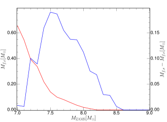
Figure 10 shows the location where carbon burning is extinguished (red curve, left y-axis) for the non-rotating models with baseline mixing parameters. The distance (in mass coordinates) that the flame traveled from birth to death is shown by the blue curve and the right y-axis. For 7.0 MZAMS 8.2, carbon burning does not reach the center. As the ZAMS mass increases, the flame or flashes get closer to the center, eventually reaching the center at 8.2 . In terms of the mass traversed, the flame (or flashes) increases its travel distance from 7.0 to 7.5 and then decreases for higher mass models. This transition occurs as stars with masses between 7.0 and 7.5 undergo a one or more of flashes, where each flash does not travel, but each subsequent flashes ignites closer to the core. For higher mass models a steady-state flame reaches the center. The dependence of these results on the chosen mixing parameters is discussed § 5.
For the models between 7.8 and 8.2 , which do not reach the center, they transition from a steady state flame into a series of flashes, as seen in Figure 3 for the 8 case. These flashes ignite in regions where the X(12C) abundance has dropped due to the mixing. A subsequent flash thus requires a higher critical density (see equation 18) to ignite in the presence of a lower abundance of carbon. These flashes are able to drive a local expansion of the core and the critical density to move inwards into the core, analogous to the flashes seen in the models. The flashes eventually stop forming once the core can no longer reach the critical density leaving unburned carbon in the core.
5. Results From The Grid Of Rotating and Overshooting Models
In this section we investigate the impact of rotation and convective overshoot on carbon burning in the SAGB models using the range of values in Table 2 and baseline mixing parameters listed in Table 1. As an example of the rotation characteristics in the carbon core, Figure LABEL:fig:f1 shows the angular momentum diffusion coefficients, specific angular momentum, angular frequency, and magnetic field profiles at first carbon ignition for an 8.0 ZAMS model with =0.2. Rotation is initialized by imposing a solid body rotation law at ZAMS. For =0.2 this corresponds to an initial angular frequency of =1.52210-5 rad s-1 and a total angular momentum of =1.901051 erg s. At first carbon ignition, Figure LABEL:fig:f1 (middle panel) shows the carbon core has spun up a factor of 30 to 610-4 rad s-1 and rotates as a solid body. The largest angular momentum diffusion coefficient, by several orders of magnitude, at first carbon ignition is due to the Spruit-Tayler dynamo. The implied 1 MG radial component of the magnetic field is shown in the bottom panel. DSI and SSI are not shown due to their negligible contributions in this model.
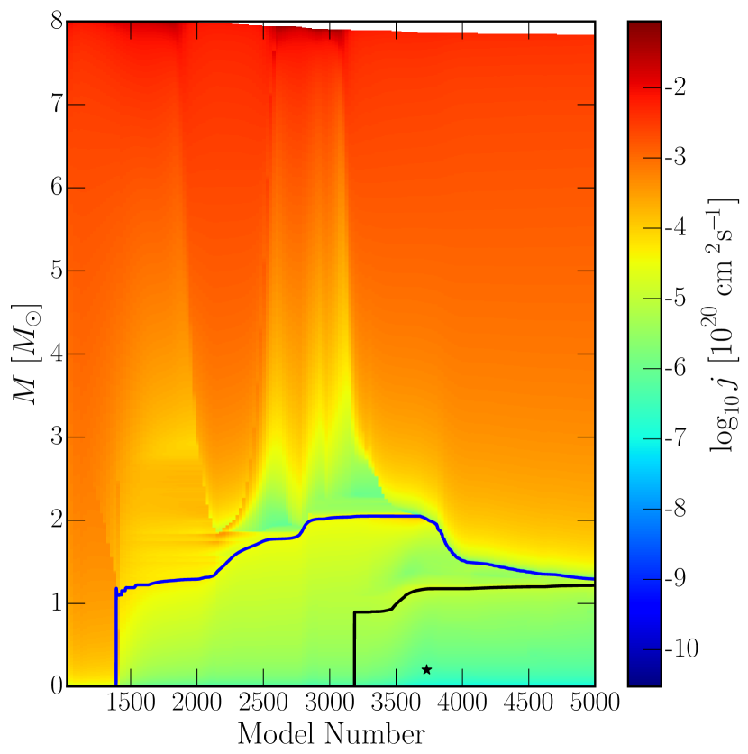
Figure 12 illustrates the evolution of the specific angular momentum from ZAMS to first carbon ignition for the 8.0 ZAMS model initialized at ZAMS with =0.25 star and =0.016. During the main-sequence phase (model numbers 10001400) the specific angular momentum is uniformly distributed throughout the model. As the star ascends the RGB and then the AGB (model numbers 14003200) the specific angular momentum is extracted from the core and redistributed into the envelope, decreasing the specific angular momentum in the core by a factor of 100. Boundaries between convective and non-convective regions are distinguished by sharp transitions in the specific angular momentum, with non-convective regions having the least specific angular momentum. The first ignition of carbon, off-center in this case, occurs around model 3700 and is marked.
While Poelarends et al. (2008) claims that mass loss will strongly effect the final outcome of SAGB, we note that in our models (with a only one mass loss rate used) that mass loss seems to have a minimal effect on the star up to carbon ignition. In figure 12 the effect of mass loss is visible as the white region at the top of the figure and only significant near the end of the core helium burning phase. While mass loss will extract angular momentum from the star, the core’s angular momentum is unaffected.
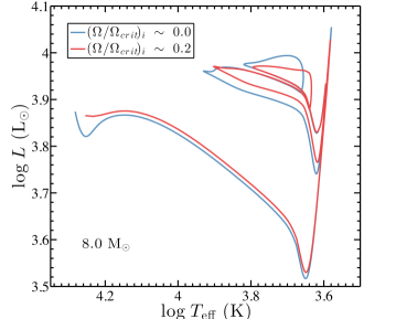
Rotation during the main sequence supplies a prolonged source of hydrogen fuel that builds a slightly more massive helium core than non-rotating models (e.g., Maeder & Meynet, 2000; Heger et al., 2000; Lagarde et al., 2012). The increase in core mass ( ), shifts the effective temperature and luminosity. However, once core helium is depleted the two tracks converge on the AGB and there is little difference in the CO core masses between rotating and non-rotating stars. Figure 13 shows a portion of the Hertzsprung-Russel diagram of two 8 ZAMS models from H depletion to He depletion: one with =0.0 (blue curve), and one with =0.2 (red curve).
5.1. Evolution of Core Rotation
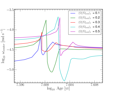
Figure 14 (left panel) shows the evolution of the central rotation rate, , for different initial rotation rates for the 7.5 ZAMS mass model. During the main-sequence phase there is little evolution in the central rotation rate, spinning down by . Figure 14 (left panel) shows the transition region between core hydrogen burning to shell hydrogen burning and then to core helium burning. As a star leaves the core hydrogen burning phase ( for the =0.1 model), the nuclear energy in the core decreases. This causes a contraction of the core and subsequently a spin up of the core (Palacios et al., 2006). The convective core spins at a constant rate throughout the convective region, and spins faster than the outer-non convective layers. As the nuclear energy generated decreases, the convective region inside the core shrinks towards the center (Sills & Pinsonneault, 2000). As it shrinks, magnetic fields in the outer radiative layers propagate inwards into regions which where previously convective. These fields act to slow down the core, removing the rotation differential between the core and the envelope.
Eventually the convective region recedes entirely allowing the magnetic fields to propagate through to the center, which causes the rapid spin down of . At this point the core is still contracting, thus the core begins to spin up again.
There are now two possible outcomes, seen in Figure 14 (left panel), either the core has a second peak in core rotation (=0.1,0.3,0.5) or the core rotation plateaus (=0.2,0.4), the outcome of which depends on the sign of . Stars with form a second peak in the core rotation profile. When convection restarts in the core, due to helium burning, the convective region expands outwards. As it does so it engulfs slower rotating material, which slows down the convective center of the star. Hence the second peak in core rotation occurs when convection restarts. For stars with , a plateau is reached in the core rotation profile. Here, when the convection restarts and expands outwards it engulfs faster rotating material and thus spins up. However this forces the convective core to expand, thus as more material is engulfed in to the convective region, it will begin to slow the core down. Hence the maximum occurs after convection has started. Typically, we find that the convective core will grow to before the spin up ceases. While we believe these qualitative aspects hold, we caution against inferring quantitative predictions from this, as we have found that the sign of to be model resolution dependent.
Figure 14 (right panel) show the evolution of at the end of the core helium burning phase up to the start of carbon burning. Note the change in the scale of ; the centers have spun down by , during the core helium burning phase. First, we see a glitch in the rotation rate at the end of the core helium phase. This is due to the same process that occurs at the end of core hydrogen burning. The convective core shrinks, allowing the magnetic fields to propagate inwards slowing the core down. This is countered by the core contracting and spinning up. We can also see that the initially faster rotating stars are evolving slower due to their ability to mix fresh fuel into the core (Maeder & Meynet, 2000; Heger et al., 2000).
We see that as the star forms its CO core the core spins up, due to the core contraction. Carbon ignition occurs at the glitches seen at rad s-1, when all stars have the same core rotation rate. These glitches occur due to the core expansion due to the carbon burning events. Subsequent episodes of carbon burning can be seen as smaller rotation glitches in figure 14 (right panel insert). We can also see that the faster the star initially rotates, the later the ignition occurs, due to their slower evolution.
5.2. Mass-Rotation Plane
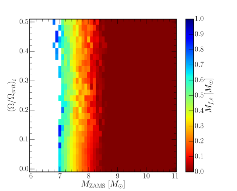
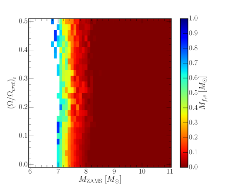
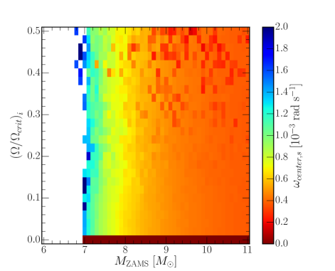

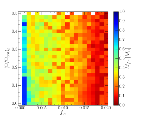
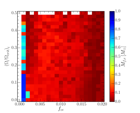
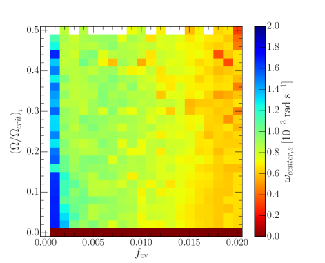
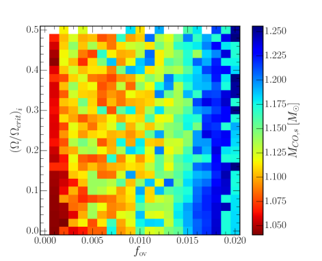
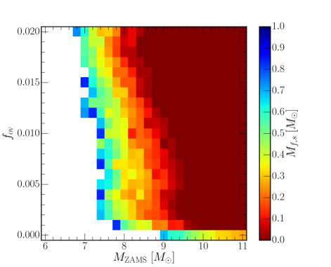
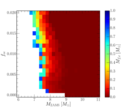
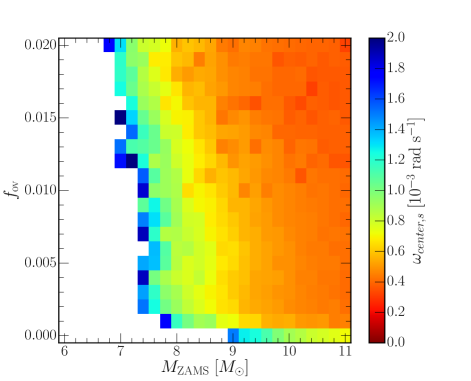
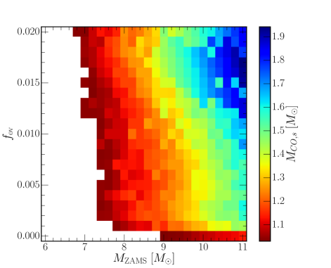
Figure 15 (top left) shows the location of the first carbon ignition in the mass-rotation plane for a fixed =0.016. Only models with 7 8 feature off-center ignition, as models with do not ignite carbon, while models with feature central carbon ignition. Figure 15 (top right) shows the location where carbon flames and flashes are quenched. Only models having off-center ignition within the relatively narrow range 8.0 8.2 does the flames or flashes reach the center.
For a fixed ZAMS mass the ignition and quenching locations are mostly independent of values between 0.0 and 0.5. This occurs because the transport of angular momentum transport from the core to the overlying layers is efficient during the giant branch phases of evolution. Thus, regardless of the initial rotation rate, by the time the carbon core forms the central regions are rotating as a solid body with similar angular frequencies for a fixed ZAMS mass. Figure 15 (bottom left) shows the center angular frequency, , in the mass-rotation plane at the fixed baseline overshoot value. Note only spans a factor of 2 over the entire plane; all models rotate with similar angular frequencies at a fixed ZAMS mass. We can quantitatively explain, to first order, the rate at which the carbon core spins up between formation of the carbon core and first ignition of carbon from angular momentum conservation and the mass-radius relationship of polytropes. When the rotating carbon core forms, its total angular momentum is
| (20) |
where is the moment of inertia, is the mass of the carbon core, is the radius of the carbon core, and is a constant that depends on the density structure. At first ignition of carbon, the angular momentum of the more massive contracting CO core is
| (21) |
Conserving angular momentum over this phase of evolution gives
| (22) |
Assuming the non-rotating polytropic mass-radius relation
| (23) |
applies at the first order, substitution into eq. 22 gives
| (24) |
where is the polytropic index at the formation of the carbon core and is the polytropic index at first carbon ignition. For the angular frequency of the core to increase, , the polytropic index is restricted to be in the range 1 3. For example, for an 8 ZAMS model with =0.2 at formation of the carbon core, we find 0.92 and 1.5. Using a least squares fitting program to generate the polytropic index for a sequence of MESA profiles between formation of the carbon core and first carbon ignition (see Figure 7 for an example), we find the left-hand side and the right-hand side of eq. 24 agree to within a factor of 2 for the 7 , 8 , and 9 models shown in Figure 15. The center spins up, on average, by a factor of 40 between formation of the carbon core and first carbon ignition. Since the carbon core at first ignition rotates as a solid body with similar angular frequencies for a fixed ZAMS mass, the carbon core masses are nearly in the same state independent of the initial rotation rate, as shown in Figure 15 (bottom right).
We find the carbon cores are rotating with periods between 0.11.0 days at first carbon ignition on the AGB. During the RGB phase of evolution we find the helium cores have periods of 2.5 days, again independent of the initial rotation rate. Mosser et al. (2012) measured rotational splittings in a sample of about 300 red giants observed during more than two years with Kepler. They found these splittings are dominated by core rotation. Periods range between 10100 days with larger periods for red clump stars compared to RGB stars. They inferred a ZAMS mass range of 1.21.5 , less massive than our rotating SAGB models.
Stars with masses will eventually form CO WDs after removing their outer envelopes. Between 7 and 8 where the carbon burning does not reach the core, our models suggest these stars will form CO+ONe hybrid WDs. Stars with masses form ONe WDs as the carbon flames will burn away the 12C. Electron capture supernovae are expected for stars with masses 9 , due to the CO core mass being greater than the Chandrasekhar mass (Eldridge & Tout, 2004).
5.3. Overshoot-Rotation Plane
Figure 16 (top left) shows the location of the first carbon ignition in the overshoot-rotation plane for a fixed ZAMS mass of 8 . For this case, overshoot is a dominant factor in setting the location of the first, off-center, carbon ignition. This first ignition of carbon can be made to occur at almost any mass coordinate within the carbon core of the 8 model by varying the overshoot parameter. The =0.0 case, where convective mixing operates only within the Schwarzschild boundaries and does not extend beyond the MLT convective boundary, does not ignite carbon for any of the initial rotations rates. The smallest non-zero overshoot parameter in our grid, =0.001, gives mass locations for the first ignition of carbon that are furthest from the center, closest to the outer boundary of the carbon core. Progressively larger values of the overshoot parameter generally move the location of the off-center ignition location closer to the center.
Figure 16 (top right) shows the quenching location, where the flame and flashes die, in the overshoot-rotation plane for a fixed ZAMS mass of 8 . The flame and flashes approaches the center for nearly all the models; only models with does the burning become quenched relatively far from the center (Denissenkov et al., 2013). Similar to our analysis the mass-rotation plane, Figure 16 (bottom left) shows carbon core rotation rate is approximately constant, to within a factor of 2, regardless of the initial rotation rate. There is evidence for a weak dependence on the rotation rate to the overshoot parameter. Figure 16 (bottom right) shows the carbon core mass increases with increasing values of , again nearly independent of the initial . A larger core mass, in turn, leads to the first carbon ignition occurring deeper in the star.
Comparing the results of the overshoot-rotation grid with the mass-rotation grid, we find the carbon core mass is the quantity that most strongly determines the structure of the flame. For example, the boundary between cases that ignite off center and those that do not ignite carbon (ZAMS masses 7 ) depends on whether the star can form a carbon core of 1.05 , which is necessary to reach the critical density in equation 18.
5.4. Mass-Overshoot Plane
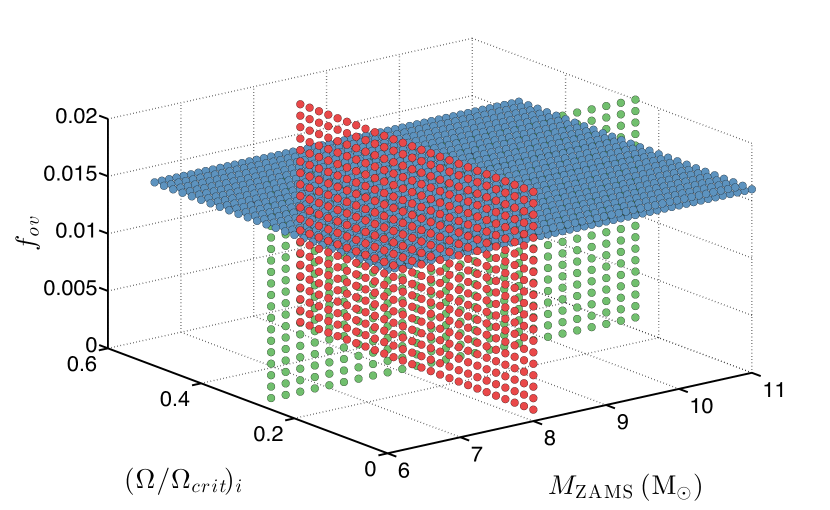
Figure 17 (top left) shows the mass location of carbon ignition in the mass-overshoot plane at a fixed ZAMS rotation of =0.25. For =0.0 the minimum mass needed to ignite carbon is 9 , 2 greater than the baseline case, and models up to 11 ignite carbon off-center. While no overshoot may be unphysical, even a small amount of overshoot moves the minimum ZAMS mass for ignition considerably, down to 7.8 . Increasing decreases the required ZAMS mass to off-center carbon ignition and decreases the minimum ZAMS mass needed for central ignition of carbon.
The width of the ZAMS mass range where the model stars ignite carbon off-center is approximately constant with respect to overshoot, / 1.6 . That is, overshoot uniformly moves the ZAMS mass boundaries where off-center carbon ignition occurs. For example, the sloped contours in Figure 17 (top left) show that when =0.0, models in the mass range 8.9 to 11 have off-center ignition (as found by e.g. Siess, 2006, 2007) When =0.008 this mass range shifts to 7.4 to 9.4 , and when =0.016 the off-center carbon ignition range shifts to 7.2 to 8.8 .
Figure 17 (top right) shows the final fate of the carbon burning flames and flashes, the quenching location in the mass-overshoot plane. With =0.0, all flames and flashes reach the core (e.g., bottom right plot of Figure 3). As the overshoot parameter increases, the carbon burning is less likely to reach the center. For 0.01, the flame either has a single flash (similar to Figure 3 top left panel for the 7 model) or undergoes a single flash then a steady state flame (similar to Figure 3 middle right panel for the 8.2 model). Only when the overshoot parameter is large, , does an intermediate evolution of a flash and then a steady state flame that does not reach the core (similar to Figure 3 middle left panel for the 8.0 model).
Figure 17 (bottom left) shows the central angular frequency at the point of first ignition in the mass-overshoot plane with a fixed ZAMS rotation of =0.25. We find that models which undergo central carbon ignition have lower angular frequencies than the off-center igniting stars. This is due to the carbon cores being spun up during the cooling phase, due to the contraction of the carbon core (see equation 24). As the heavier stars ignite carbon earlier they have less time in which to be spun up compared to the lower mass stars have at first ignition. As before, only models with carbon core masses greater than 1.05 ignite carbon, as shown in in Figure 17 (bottom right). As before, the maximum carbon core mass that ignites off-center carbon burning is 1.2 , similar to that shown in Figures 15 and 16.
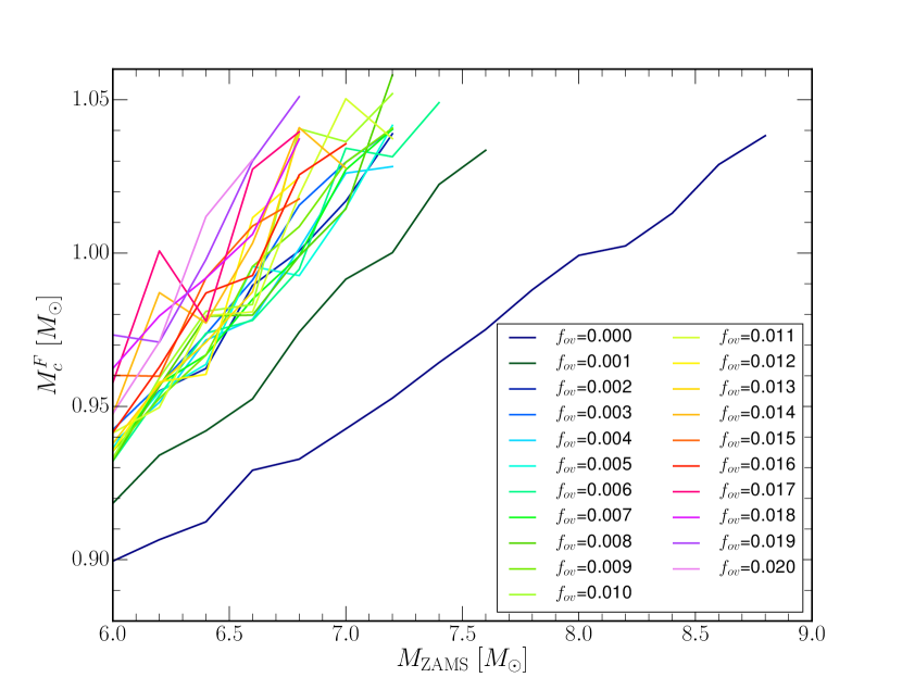
Figure 18 shows the final CO core mass for the non-igniting models (white region in Figure 17). The maximum mass for a CO core is 1.05 ; stars with heavier CO cores ignite carbon burning. We also find a trend for increasing overshoot to increase the final CO core mass, as noted previously. Doherty et al. (2015) reported a grid of models with the Monash stellar evolution code, over a range of metallicities, to investigate the fate of AGB and SAGB stars. Comparing our results with their solar metalicity results (their Fig. 6), we find that for a given ZAMS mass our rotating CO core masses are 0.050.1 larger. Increasing the overshoot can mimic decreasing the metalicity in terms of the final CO WD mass.
h
| 0.0 | 0.5 | 1.0 | 1.5 | ||||||||||||||
| 0.000 | 0.001 | 0.016 | 0.020 | 0.000 | 0.001 | 0.016 | 0.020 | 0.000 | 0.001 | 0.016 | 0.020 | 0.000 | 0.001 | 0.016 | 0.020 | ||
| 0.000 | 0.00 | 333Ellipses represents models with no ignition | 0.65 | 0.28 | 0.49 | 0.15 | 0.18 | 0.43 | 0.17 | 0.16 | 0.49 | 0.17 | 0.13 | ||||
| 0.000 | 0.10 | 0.50 | 0.71 | 0.46 | 0.17 | 0.05 | 0.43 | 0.42 | 0.14 | 0.05 | 0.47 | 0.18 | 0.05 | ||||
| 0.000 | 1.00 | 0.63 | 0.35 | 0.38 | 0.39 | 0.46 | 0.11 | 0.18 | 0.40 | 0.16 | 0.16 | 0.48 | 0.15 | 0.16 | |||
| 0.000 | 10.0 | 0.50 | 0.65 | 0.54 | 0.49 | 0.16 | 0.15 | 0.43 | 0.18 | 0.05 | 0.43 | 0.14 | 0.16 | ||||
| 0.001 | 0.00 | 0.81 | 0.65 | 0.59 | 0.21 | 0.17 | 0.83 | 0.16 | 0.14 | 0.85 | 0.23 | 0.04 | |||||
| 0.001 | 0.10 | 0.79 | 0.48 | 0.28 | 0.37 | 0.83 | 0.20 | 0.05 | 0.85 | 0.14 | 0.18 | 0.69 | 0.12 | 0.05 | |||
| 0.001 | 1.00 | 0.83 | 0.58 | 0.71 | 0.84 | 0.15 | 0.17 | 0.83 | 0.18 | 0.05 | 0.71 | 0.17 | 0.15 | ||||
| 0.001 | 10.0 | 0.33 | 0.69 | 0.32 | 0.49 | 0.57 | 0.18 | 0.16 | 0.62 | 0.08 | 0.05 | 0.65 | 0.11 | 0.16 | |||
| 0.010 | 0.00 | 0.19 | 0.57 | 0.45 | 0.75 | 0.63 | 0.21 | 0.16 | 0.65 | 0.17 | 0.14 | 0.63 | 0.16 | 0.05 | |||
| 0.010 | 0.10 | 0.30 | 0.39 | 0.69 | 0.20 | 0.05 | 0.62 | 0.13 | 0.04 | 0.68 | 0.12 | 0.05 | |||||
| 0.010 | 1.00 | 0.73 | 0.73 | 0.66 | 0.17 | 0.18 | 0.55 | 0.20444Baseline model | 0.05 | 0.85 | 0.16 | 0.14 | |||||
| 0.010 | 10.0 | 0.49 | 0.57 | 0.66 | 0.36 | 0.56 | 0.18 | 0.04 | 0.63 | 0.08 | 0.17 | 0.64 | 0.10 | 0.05 | |||
| 0.100 | 0.00 | 0.28 | 0.39 | 0.76 | 0.66 | 0.12 | 0.17 | 0.84 | 0.15 | 0.14 | 0.83 | 0.16 | 0.06 | ||||
| 0.100 | 0.10 | 0.54 | 0.28 | 0.37 | 0.52 | 0.20 | 0.08 | 0.58 | 0.14 | 0.17 | 0.83 | 0.11 | 0.05 | ||||
| 0.100 | 1.00 | 0.51 | 0.57 | 0.73 | 0.68 | 0.15 | 0.18 | 0.83 | 0.20 | 0.06 | 0.55 | 0.17 | 0.13 | ||||
| 0.100 | 10.0 | 0.69 | 0.52 | 0.55 | 0.49 | 0.18 | 0.04 | 0.58 | 0.08 | 0.15 | 0.60 | 0.12 | 0.16 | ||||

6. Results From The Mixing Coefficient Grid Studies
Table 5 shows overshoot has the most significant effect, on the location of the initial flame, with no ignition for no overshoot for the 8, =0.25 model, as long as the scale factor for the strength of angular momentum diffusion . As overshoot increases, the flame ignition occurs deeper in the star. This is due to changes in the 4He and CO core masses during the stars evolution. For instance, comparing Figure 3 bottom left and bottom right, we can see the effect of overshoot for the 9 model. Primarily, the model with overshoot ignites at the center, while the no overshoot model ignites off center. Without overshoot the CO core mass, the size of the helium shell and the ignition location are comparable to the 7 model with overshoot.
There are two distinct populations in the thermohaline models, those with small values of , which ignite a flame at 0.5 and those with large values which ignite a flash at 0.8 (though only if =0.001). Those models that ignite at 0.5 , thermohaline mixing has little impact on the flame ignition location. However there is some variation due to thermohaline mixing before the flame ignites. Before the flame ignites, when , there is a region in the vicinity of the ignition point that undergoes weak 12C+12C burning (with ). This weak burning is able to drive a region of weak thermohaline mixing as a precursor to the vigorous carbon burning. Those that ignite at ignite a flash, but under different conditions to those that we predict for the other flashes. Here, there is thermohaline mixing between the CO and helium shell which allows us to form a small region () where CO. This higher fraction of carbon allows the ignition to occur at a lower density. This flash then prevents an ignition occurring deeper in the CO core where C, which we assume in equation 14.
Thermohaline mixing also effects the flame once burning has commenced, the mixing pulls 12C material from below the flame (Siess, 2009). As the strength of thermohaline mixing increases, the sub flashes, seen in figure 3, middle left panel, merge into one continuous flame, due to the increased carbon abundance. However as Siess (2009) showed this mixing eventually starves the flame of fuel preventing it from reaching the core.
The effect of semiconvection is almost negligible, over the range of values considered here. Semiconvection acts near regions of convection, however it only acts for short periods of time in our models, thus has limited ability to change the composition of models before the formation of the CO core. In can however act during the carbon burning once the convective region has formed, mixing the burnt material with unburnt CO. Again this effect is small and plays a limited role the evolution of the flame. In figure 3, where we have secondary carbon flashes (top left, middle left and middle right panels), those flashes that occur near the 4He shell can form brief semiconvective regions across the shell and into the convective envelope. This may provide a way to detect the product of the flashes in the surface abundances, though these flashes (and the semi convective regions) are short lived, which will limit the material transferred.
Changes in , which is a global scale factor on the strength of angular momentum mixing, primarily acts by changing the strength of thermohaline mixing. As increases the amount of thermohaline mixing increases as well, which allows the mixing of material from the core into the flame (Siess, 2009) to increase, though again this effect is small.
Zaussinger & Spruit (2013) found for a 15 model on the MS that the semiconvection mixing timescale is long (yrs) which explains why the semiconvection has little effect on these systems. Siess (2009) showed that thermohaline mixing has limited effect in the evolution up to the carbon ignition, due to the lack of the 3He(3He,2p)4He reaction which is necessary to set up the mean molecular weight inversion needed for thermohaline mixing. Brown et al. (2013) propose a model for mixing by fingering convection in the parameter regime relevant for stellar (and planetary) interiors that is supported by three-dimensional direct numerical simulations.
The angular momentum diffusion term has limited impact due to its implementation as a global scale factor on the angular momentum mixing process (Paxton et al., 2013), thus the value itself is not physically motivated however we have varied to test whether missing sources of angular momentum, like internal gravity waves (Kumar & Quataert, 1997), would have an impact. Given however, that in Figure LABEL:fig:f1 we have shown that the individual diffusion coefficients can vary by 10 orders of magnitude, a change of 50% in is insignificant. For additional sources of angular momentum mixing to have an impact, they must be able to effect size of the CO core, like overshoot does, to have a detectable impact. Compositional changes (thermohaline and semiconvection) are too weak to have appreciable impact on the ignition location due to their limited ability to change the CO core mass.
7. Results From The Spatial And Temporal Convergence Studies
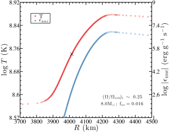
Accurately capturing the nuclear burning and thermal transport within a steady-state, convectively bounded, carbon burning front, or within the time-dependent carbon burning flashes, requires spatial resolutions km (Timmes et al., 1994; Ritossa et al., 1996; García-Berro et al., 1997). Siess (2006) use as many as 50 grid points to describe the precursor flame between the convection region and the minimum in the luminosity profile below the convective region. Denissenkov et al. (2013) and Chen et al. (2014) use more than 100 mass zones. Figure 19 shows the temperature and nuclear energy generation rate profiles of a carbon burning flame in our 8 ZAMS model with =0.25 and =0.016. Distances 3700 km lie ahead of the flame front, and distances between 3700 km and 3900 km contain the region where thermal conduction dominates nuclear burning. Distances between 3900 km and 4200 km contains the body of the flame front which reaches a peak temperature of 7.5108 K and peak energy generation rates of 8.9106 erg g-1 s-1. Distances 4200 km contain the convectively bounded region of the flame. The critical temperature at which the heating due to nuclear reactions equals the energy diffused away by neutrino and conductive processes in the steady state is about 5.5108 K. The location of this critical temperature is marked in Figure 19 with a black cross. The profiles shown in Figure 19 also capture the flame structure with 12 km resolution with 400 mesh points. The flame structure propagates inward toward the center at speeds of 0.1 cm s-1, consistent with the values reported in Timmes et al. (1994).
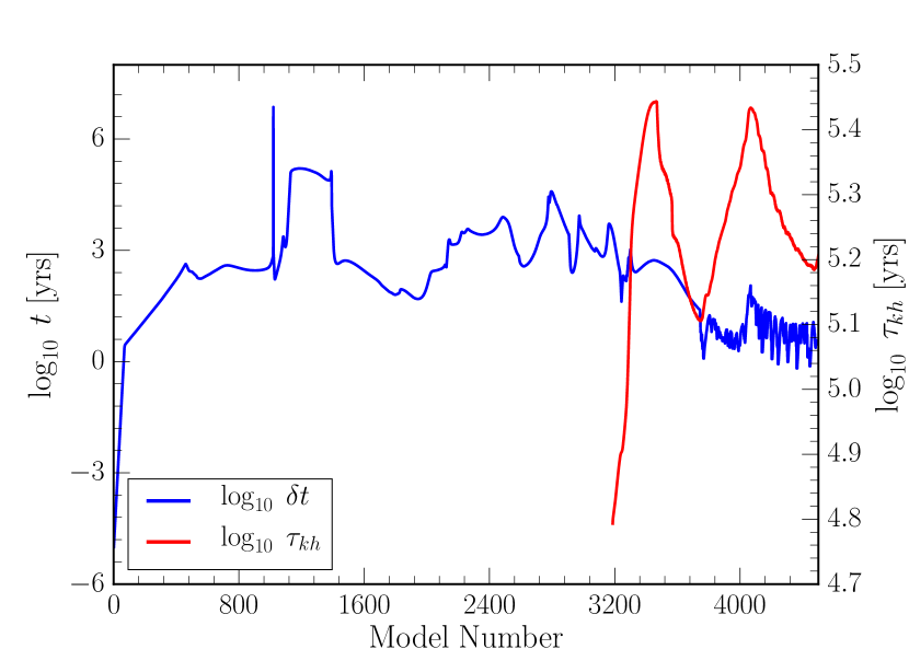
Figure 20 shows the timestep and Kelvin-Helmholtz thermal timescale, , for the CO core of the 8 ZAMS model with =0.25 and =0.016 model. As helium is depleted in the core at model number 2800, the timestep begins to decrease from 10,000 years due to the increase in nuclear burning. At first carbon ignition, model 3700, the timestep is 10 years and decreases to 1 year as the flame and flashes propagate towards the center. At model number 4500 the flashes have reached their closest approach to the center. The thermal timescale increases as the core increases in mass until the first ignition, where it then rapidly decreases due to the increased luminosity. The thermal timescale then peaks again shortly before the next ignition at model 4400. This time however the flame generates less energy and the thermal timescale is reduced by a smaller amount, compared to the first ignition. On average the flame lifetime is 10% that of the thermal timescale of the core.
The location of first carbon ignition in the 7 , 8 , and 9 models as a function of spatial and temporal resolution is shown in Figure 21. Each model has the baseline =0.016. Spatial resolution in MESA is generally controlled by , with smaller values providing an increase in the number of cells. Temporal resolution is loosely controlled by , the allowed change in the size of variables during a timestep, with smaller values decreasing the size of the timesteps taken. See (Paxton et al., 2011) for a detailed discussion of these two MESA control parameters.
For zero rotation, Figure 21 (top left) shows all values of and give the same location of first carbon ignition, suggesting convergence has been attained. Increasing the spatial resolution has little impact on the location of the flame, while increasing the temporal resolution shows a slight decrease in the ignition location.
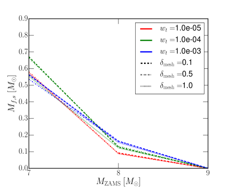
For =0.25 (Figure 21 top right), the location of first carbon ignition depends on the values of and . For the 7 case the highest resolution model (red-dashed), and =0.1, agree with our baseline model (green-dot-dashed), and =0.5, that there is no ignition occurs. At , as the spatial resolution decreases the ignition point is pushed deeper into the star. At 8 , most of the models have converge around 0.1-0.2 ignition point, except the lowest resolution model with has a center ignition. Models with show little variation as changes, while as increases in size the term becomes more significant. These studies suggest our baseline values for and for off-center ignition are well within the convergence envelope. All models converge on a 9 star having center ignition.
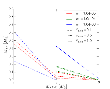
At =0.5 (Figure 21 bottom), for the 7 case our baseline parameters agree with the highest resolution model, for the lack of ignition. However, for all other values of and there is considerable spread in ignition points. For the 8 case the results have clustered around 0.05-2.0, except for case, where the results have a spread of 0.5. All models agree again the 9 case has a central ignition.
Overall, our baseline models agree within 0.1 of the highest resolution models we ran, for the ignition point. As the rotation rate of the star increases we can see that the choice of resolution terms becomes more significant and that there is a larger spread in possible values. Changing the temporal resolution has the most effect on the initial location of the flame. The choice of spatial resolution becomes more significant only as the temporal resolution decreases. Thus our choice of baseline parameters appear to be a good compromise in terms of precision of results and computational effort, decreasing increases the computational time by a similar amount, while decreasing increases the memory requirements for the model. However, they also show a necessary requirement for carbon flame modelers to look critically at their choice of model resolution (Timmes et al., 1994; Ritossa et al., 1996; Siess, 2006; Doherty et al., 2010; Denissenkov et al., 2013; Chen et al., 2014).
8. Discussion
We have investigated the detailed and global properties of carbon burning in SAGB stars with 2755 stellar evolution models. These models consumed 200,000 core-hours (roughly 3 days per model) and yielded over 2 TB of decimated data (a limited number of MESA profiles were stored). To our knowledge this represents the largest block of compute resources used for a MESA survey to date. We note that every model ran from the pre-main-sequence to the end of carbon burning (if carbon ignition was achieved) without failure and without intervention.
With these models, the location of first ignition whether off-center or central, the quenching location of the carbon burning flames and flashes, the angular frequency of the carbon core, and the carbon core mass have been surveyed as a function of the ZAMS mass, initial rotation rate, the magnitude of various mixing parameters such as convective overshoot, semiconvection, thermohaline and angular momentum transport. We now compare our results to previous efforts and discuss methods for calibrating the parameter within a given overshoot implementation.
Georgy et al. (2013) found that rotation of a 9 model can increase the lifetime spent on the MS compared to that of a non-rotating model. This increase in MS lifetime is caused by rotational mixing supplying a sustained amount of fresh hydrogen into the convective core. They include modifications to the stellar structure equations due to centrifugal acceleration described by Kippenhahn et al. (1970); Endal & Sofia (1976), assuming the angular velocity is constant on isobars (Zahn, 1992). Georgy et al. (2013) also adopt an instantaneous method of overshoot with applied to the H- and He- burning boundaries. For a non-rotating 9 model at the end of core He burning they find a convective core to total mass ratio of while our corresponding rotating model yields a larger value of . We find a more modest difference between the non-rotating and rotating 8 model of and , respectively, as shown in Figure 13.
While our MESA models use a similar implementation for rotation, our calculations differ from Georgy et al. (2013) in that we include the effects magnetic torques which aid in significantly inhibiting the spin up of the convective core of the star during its evolution. For example, we find for an 8 ZAMS model with , an angular velocity at the center of the core of at the start of carbon ignition, compared to a more rapid value of when internal magnetic fields are neglected. Magnetic field torques that inhibit spin up of the stellar model results in less massive convective cores due to the less efficient rotational mixing. We also find that magnetic torques can account for the less drastic shift in luminosity on the HRD for an 8.0 ZAMS model with 0.2 (See Figure 13), contrary to the larger differences in the rotating model HRD tracks shown in Georgy et al. (2012).
For their stars past 2DU, Doherty et al. (2015) found the CO core mass for a 7 ZAMS model to be 0.8 and increases to 1.375 for their 9.5 ZAMS models. In mild contrast, our models predict the CO core mass for a 7 ZAMS model to be and the highest mass star to produce a Chandrasekhar core to be a 9 ZAMS, assuming an overshoot of =0.016. These differences are likely due to the treatment of the convective boundaries, with Doherty et al. (2015) using a search for convective neutrality rather than a convective-decay prescription, leading to differences in the size of the 4He and CO core masses.
Siess (2006) found for models without overshoot that the ZAMS mass range which ignite carbon off-center is 911.3 . This is comparable to our , rotating models (Figure 17), which yield a value of and 11.
Denissenkov et al. (2013) found for a 9.5 ZAMS mass with no overshoot or thermohaline mixing, an off-center ignition mass of 0.665 with the flame proceeding to the center, consistent with our results. With =0.007 they found carbon ignites off-center but the flames and flashes do not reach the center. In contrast, we find in this case the model star undergoes a central ignition. We speculate this difference is due to Denissenkov et al. (2013) only including overshoot once the CO core has formed, where we include it from the pre-MS onwards. Thus, the CO core in Denissenkov et al. (2013), =0.007 model will be smaller than our models, and hence the ignition occurring off-center.
While our models are not completely comparable to those of Jones et al. (2013), who use =0.014 except at the base of a burning region where they use =0.007, they find a 8.2 model ignites off-center while models with 8.8 centrally ignite. We find that for models with 0.007 0.014 that a 8.2 will ignite off-center while only models with 9.4 will always centrally ignite.
Arguably the biggest uncertainty in stellar models is the treatment of convection. The overshooting parameter in particular, regardless of how it is implemented within a specific numerical instrument, critically influences all outputs of stellar evolution (e.g. Maeder, 1975, 1976). Figure 17 in particular demonstrates that the properties of carbon burning in SAGB models is not an exception, especially the range of ZAMS masses that experience off-center ignition. Testing on a small number of models suggests that the most significant location for overshoot is in regions of He burning, followed by carbon burning. Regions with H burning or no burning show little difference in ignition location with respect to changes in overshoot. The effect of convective overshoot on the stellar models considered in this work are in agreement with previous work by Siess (2007) who showed that for applied at the edge of the convective boundary, Mup can transition from 8.90 0.10 to 7.25 0.25 for . We find a similar transition where for our rotating, = 0.0 model, which shifts to a value of M 7.2 for = 0.016 (See Figure 17). Gil-Pons et al. (2007) found similar results upon investigating a grid of zero metallicity stars with using an instantaneous overshooting formalism (Herwig et al., 1997), contrary to the diffusive approach used in this work. They find a value of 6.0 and 7.8 . The adoption of instantaneous overshooting, as well as are likely to contribute to the modest discrepancy in values of and .
Traditionally the value of the overshooting parameter for a given overshooting model is calibrated by fitting isochrones against the width of the terminal age main sequence in color-magnitude diagrams, or the surface abundances, of young and intermediate age clusters (e.g., Maeder, 1976; Maeder & Mermilliod, 1981; Mermilliod & Maeder, 1986; Schaller et al., 1992; Herwig, 2000; VandenBerg et al., 2006; Kamath et al., 2012). Photometry and spectroscopy of binary systems offer another avenue for calibration of overshooting because these measurements can provide the radii, effective temperatures, and masses. In addition both components of the binary need to lie on the same isochrone and fit their respective evolutionary tracks (Schroder et al., 1997; Pols et al., 1997; Ribas et al., 2000; Claret, 2007; Meng & Zhang, 2014; Stancliffe et al., 2015) High-precision high-cadence space photometry from the CoRoT and Kepler missions opens up a newer method for calibration of overshooting and other mixing processes in stellar interiors (Neiner et al., 2012; Montalbán et al., 2013; Tkachenko et al., 2014; Guenther et al., 2014; Aerts, 2015).
MESA implements the time-dependent treatment of convective overshoot mixing of Herwig (2000) with the traditional calibration method leading to =0.016. It is unknown if this value of in this specific overshoot model applies to masses other than the ones used for calibration, is consistent with values derived from binary systems or asteroseismology, or if it applies to advanced burning stages of stellar evolution. However, we have shown that for a dense grid of SAGB models taken to the end of carbon burning, utilizing our adopted baseline parameters, values of and 8.4 are nearly independent of initial of ZAMS rotational values of 0.0 - 0.5. While our SAGB models have been evolved from the pre-MS phase through the end of carbon burning, for models whom do not ignite carbon, and those that ignite carbon off-center, the initial rotational rate may play a larger role in the final rotational rates of the WD that will eventually be born. For a given ZAMS mass and overshoot parameterization, we suggest that strong claims of carbon burning quenching at an appreciable distance from the center to yield hybrid CO + ONeNa white dwarfs should be viewed with caution.
References
- Aerts (2015) Aerts, C. 2015, in IAU Symposium, Vol. 307, IAU Symposium, 154–164
- Alastuey & Jancovici (1978) Alastuey, A., & Jancovici, B. 1978, ApJ, 226, 1034
- Beaudet & Salpeter (1969) Beaudet, G., & Salpeter, E. E. 1969, ApJ, 155, 203
- Becker & Iben (1979) Becker, S. A., & Iben, Jr., I. 1979, ApJ, 232, 831
- Becker & Iben (1980) —. 1980, ApJ, 237, 111
- Berger et al. (2005) Berger, L., Koester, D., Napiwotzki, R., Reid, I. N., & Zuckerman, B. 2005, A&A, 444, 565
- Blöcker et al. (2000) Blöcker, T., Herwig, F., & Driebe, T. 2000, Mem. Soc. Astron. Italiana, 71, 711
- Bloecker (1995) Bloecker, T. 1995, A&A, 297, 727
- Böhm-Vitense (1958) Böhm-Vitense, E. 1958, ZAp, 46, 108
- Boozer et al. (1973) Boozer, A. H., Joss, P. C., & Salpeter, E. E. 1973, ApJ, 181, 393
- Brown et al. (2013) Brown, J. M., Garaud, P., & Stellmach, S. 2013, ApJ, 768, 34
- Cannon (1970) Cannon, R. D. 1970, MNRAS, 150, 111
- Cantiello & Langer (2010) Cantiello, M., & Langer, N. 2010, A&A, 521, A9
- Castellani et al. (1992) Castellani, V., Chieffi, A., & Straniero, O. 1992, ApJS, 78, 517
- Charbonnel & Zahn (2007) Charbonnel, C., & Zahn, J.-P. 2007, A&A, 467, L15
- Chen et al. (2014) Chen, M. C., Herwig, F., Denissenkov, P. A., & Paxton, B. 2014, MNRAS, 440, 1274
- Claret (2007) Claret, A. 2007, A&A, 475, 1019
- Cox & Giuli (1968) Cox, J. P., & Giuli, R. T. 1968, Principles of Stellar Structure (New York: Gordon & Breach)
- Cyburt et al. (2010) Cyburt, R. H., Amthor, A. M., Ferguson, R., et al. 2010, ApJS, 189, 240
- Davidson et al. (1982) Davidson, K., Gull, T. R., Maran, S. P., et al. 1982, ApJ, 253, 696
- Denissenkov (2010) Denissenkov, P. A. 2010, ApJ, 723, 563
- Denissenkov et al. (2013) Denissenkov, P. A., Herwig, F., Truran, J. W., & Paxton, B. 2013, ApJ, 772, 37
- Denissenkov & Merryfield (2011) Denissenkov, P. A., & Merryfield, W. J. 2011, ApJ, 727, L8
- Dewitt et al. (1973) Dewitt, H. E., Graboske, H. C., & Cooper, M. S. 1973, ApJ, 181, 439
- Doherty et al. (2014a) Doherty, C. L., Gil-Pons, P., Lau, H. H. B., Lattanzio, J. C., & Siess, L. 2014a, MNRAS, 437, 195
- Doherty et al. (2014b) Doherty, C. L., Gil-Pons, P., Lau, H. H. B., et al. 2014b, MNRAS, 441, 582
- Doherty et al. (2015) Doherty, C. L., Gil-Pons, P., Siess, L., Lattanzio, J. C., & Lau, H. H. B. 2015, MNRAS, 446, 2599
- Doherty et al. (2010) Doherty, C. L., Siess, L., Lattanzio, J. C., & Gil-Pons, P. 2010, MNRAS, 401, 1453
- Eldridge & Tout (2004) Eldridge, J. J., & Tout, C. A. 2004, MNRAS, 353, 87
- Endal & Sofia (1976) Endal, A. S., & Sofia, S. 1976, ApJ, 210, 184
- Endal & Sofia (1978) —. 1978, ApJ, 220, 279
- Faulkner & Cannon (1973) Faulkner, D. J., & Cannon, R. D. 1973, ApJ, 180, 435
- Fishlock et al. (2014) Fishlock, C. K., Karakas, A. I., Lugaro, M., & Yong, D. 2014, ApJ, 797, 44
- García-Berro et al. (1997) García-Berro, E., Ritossa, C., & Iben, Jr., I. 1997, ApJ, 485, 765
- Georgy et al. (2012) Georgy, C., Ekström, S., Meynet, G., et al. 2012, A&A, 542, A29
- Georgy et al. (2013) Georgy, C., Ekström, S., Eggenberger, P., et al. 2013, A&A, 558, A103
- Gil-Pons et al. (2007) Gil-Pons, P., Gutiérrez, J., & García-Berro, E. 2007, A&A, 464, 667
- Gil-Pons et al. (2005) Gil-Pons, P., Suda, T., Fujimoto, M. Y., & García-Berro, E. 2005, A&A, 433, 1037
- Girardi (1999) Girardi, L. 1999, MNRAS, 308, 818
- Graboske et al. (1973) Graboske, H. C., Dewitt, H. E., Grossman, A. S., & Cooper, M. S. 1973, ApJ, 181, 457
- Grevesse & Sauval (1998) Grevesse, N., & Sauval, A. J. 1998, Space Sci. Rev., 85, 161
- Guenther et al. (2014) Guenther, D. B., Demarque, P., & Gruberbauer, M. 2014, ApJ, 787, 164
- Gutierrez et al. (1996) Gutierrez, J., Garcia-Berro, E., Iben, Jr., I., et al. 1996, ApJ, 459, 701
- Hansen et al. (2004) Hansen, C. J., Kawaler, S. D., & Trimble, V. 2004, Stellar interiors : physical principles, structure, and evolution (New York: Springer-Verlag)
- Heger et al. (2000) Heger, A., Langer, N., & Woosley, S. E. 2000, ApJ, 528, 368
- Heger et al. (2005) Heger, A., Woosley, S. E., & Spruit, H. C. 2005, ApJ, 626, 350
- Herwig (2000) Herwig, F. 2000, A&A, 360, 952
- Herwig (2005) —. 2005, ARA&A, 43, 435
- Herwig et al. (1997) Herwig, F., Bloecker, T., Schoenberner, D., & El Eid, M. 1997, A&A, 324, L81
- Iben (1991) Iben, Jr., I. 1991, ApJS, 76, 55
- Itoh et al. (1996) Itoh, N., Hayashi, H., Nishikawa, A., & Kohyama, Y. 1996, ApJS, 102, 411
- Itoh et al. (1979) Itoh, N., Totsuji, H., Ichimaru, S., & Dewitt, H. E. 1979, ApJ, 234, 1079
- Jennings et al. (2012) Jennings, Z. G., Williams, B. F., Murphy, J. W., et al. 2012, ApJ, 761, 26
- Jones et al. (2013) Jones, S., Hirschi, R., Nomoto, K., et al. 2013, ApJ, 772, 150
- Kamath et al. (2012) Kamath, D., Karakas, A. I., & Wood, P. R. 2012, ApJ, 746, 20
- Karakas & Lattanzio (2014) Karakas, A. I., & Lattanzio, J. C. 2014, ArXiv e-prints
- Kippenhahn et al. (1970) Kippenhahn, R., Meyer-Hofmeister, E., & Thomas, H. C. 1970, A&A, 5, 155
- Kippenhahn et al. (1980) Kippenhahn, R., Ruschenplatt, G., & Thomas, H.-C. 1980, A&A, 91, 175
- Kippenhahn et al. (2012) Kippenhahn, R., Weigert, A., & Weiss, A. 2012, Stellar Structure and Evolution (Springer-Verlag: Berlin)
- Kumar & Quataert (1997) Kumar, P., & Quataert, E. J. 1997, ApJ, 475, L143
- Lagarde et al. (2012) Lagarde, N., Decressin, T., Charbonnel, C., et al. 2012, A&A, 543, A108
- Langer et al. (1985) Langer, N., El Eid, M. F., & Fricke, K. J. 1985, A&A, 145, 179
- Langer et al. (1983) Langer, N., Fricke, K. J., & Sugimoto, D. 1983, A&A, 126, 207
- Langer et al. (1999) Langer, N., Heger, A., Wellstein, S., & Herwig, F. 1999, A&A, 346, L37
- Lattanzio et al. (2015) Lattanzio, J. C., Siess, L., Church, R. P., et al. 2015, MNRAS, 446, 2673
- Maeder (1975) Maeder, A. 1975, A&A, 40, 303
- Maeder (1976) —. 1976, A&A, 47, 389
- Maeder & Mermilliod (1981) Maeder, A., & Mermilliod, J. C. 1981, A&A, 93, 136
- Maeder & Meynet (2000) Maeder, A., & Meynet, G. 2000, ARA&A, 38, 143
- Maeder & Meynet (2003) —. 2003, A&A, 411, 543
- Maeder & Meynet (2004) —. 2004, A&A, 422, 225
- Mazzitelli et al. (1999) Mazzitelli, I., D’Antona, F., & Ventura, P. 1999, A&A, 348, 846
- Meng & Zhang (2014) Meng, Y., & Zhang, Q. S. 2014, ApJ, 787, 127
- Mermilliod & Maeder (1986) Mermilliod, J.-C., & Maeder, A. 1986, A&A, 158, 45
- Meynet & Maeder (1997) Meynet, G., & Maeder, A. 1997, A&A, 321, 465
- Miyaji et al. (1980) Miyaji, S., Nomoto, K., Yokoi, K., & Sugimoto, D. 1980, PASJ, 32, 303
- Montalbán et al. (2013) Montalbán, J., Miglio, A., Noels, A., et al. 2013, ApJ, 766, 118
- Mosser et al. (2012) Mosser, B., Goupil, M. J., Belkacem, K., et al. 2012, A&A, 548, A10
- Neiner et al. (2012) Neiner, C., Mathis, S., Saio, H., et al. 2012, A&A, 539, A90
- Noels et al. (1991) Noels, A., Grevesse, N., Magain, P., et al. 1991, A&A, 247, 91
- Nomoto (1984) Nomoto, K. 1984, ApJ, 277, 791
- Nomoto (1987) —. 1987, ApJ, 322, 206
- Nomoto & Iben (1985) Nomoto, K., & Iben, Jr., I. 1985, ApJ, 297, 531
- Nomoto et al. (1982) Nomoto, K., Sugimoto, D., Sparks, W. M., et al. 1982, Nature, 299, 803
- Palacios et al. (2006) Palacios, A., Charbonnel, C., Talon, S., & Siess, L. 2006, A&A, 453, 261
- Paxton et al. (2011) Paxton, B., Bildsten, L., Dotter, A., et al. 2011, ApJS, 192, 3
- Paxton et al. (2013) Paxton, B., Cantiello, M., Arras, P., et al. 2013, ApJS, 208, 4
- Pinsonneault et al. (1989) Pinsonneault, M. H., Kawaler, S. D., Sofia, S., & Demarque, P. 1989, ApJ, 338, 424
- Poelarends et al. (2008) Poelarends, A. J. T., Herwig, F., Langer, N., & Heger, A. 2008, ApJ, 675, 614
- Pols et al. (1997) Pols, O. R., Tout, C. A., Schroder, K.-P., Eggleton, P. P., & Manners, J. 1997, MNRAS, 289, 869
- Rakavy et al. (1967) Rakavy, G., Shaviv, G., & Zinamon, Z. 1967, ApJ, 150, 131
- Reimers (1975) Reimers, D. 1975, Memoires of the Societe Royale des Sciences de Liege, 8, 369
- Ribas et al. (2000) Ribas, I., Jordi, C., & Giménez, Á. 2000, MNRAS, 318, L55
- Ritossa et al. (1996) Ritossa, C., Garcia-Berro, E., & Iben, Jr., I. 1996, ApJ, 460, 489
- Ritossa et al. (1999) Ritossa, C., García-Berro, E., & Iben, Jr., I. 1999, ApJ, 515, 381
- Saio & Nomoto (1998) Saio, H., & Nomoto, K. 1998, ApJ, 500, 388
- Salaris et al. (2014) Salaris, M., Weiss, A., Cassarà, L. P., Piovan, L., & Chiosi, C. 2014, A&A, 565, A9
- Schaller et al. (1992) Schaller, G., Schaerer, D., Meynet, G., & Maeder, A. 1992, A&AS, 96, 269
- Schroder et al. (1997) Schroder, K.-P., Pols, O. R., & Eggleton, P. P. 1997, MNRAS, 285, 696
- Seidel et al. (1987) Seidel, E., Demarque, P., & Weinberg, D. 1987, ApJS, 63, 917
- Siess (2006) Siess, L. 2006, A&A, 448, 717
- Siess (2007) —. 2007, A&A, 476, 893
- Siess (2009) —. 2009, A&A, 497, 463
- Siess (2010) —. 2010, A&A, 512, A10
- Sills & Pinsonneault (2000) Sills, A., & Pinsonneault, M. H. 2000, ApJ, 540, 489
- Smartt (2009) Smartt, S. J. 2009, ARA&A, 47, 63
- Spruit (1998) Spruit, H. C. 1998, A&A, 333, 603
- Spruit (2002) —. 2002, A&A, 381, 923
- Spruit (2013) —. 2013, A&A, 552, A76
- Stancliffe (2010) Stancliffe, R. J. 2010, MNRAS, 403, 505
- Stancliffe et al. (2009) Stancliffe, R. J., Chieffi, A., Lattanzio, J. C., & Church, R. P. 2009, Publications of the Astronomical Society of Australia, 26, 203
- Stancliffe et al. (2015) Stancliffe, R. J., Fossati, L., Passy, J.-C., & Schneider, F. R. N. 2015, ArXiv e-prints
- Suijs et al. (2008) Suijs, M. P. L., Langer, N., Poelarends, A.-J., et al. 2008, A&A, 481, L87
- Timmes et al. (2000) Timmes, F. X., Hoffman, R. D., & Woosley, S. E. 2000, ApJS, 129, 377
- Timmes & Woosley (1992) Timmes, F. X., & Woosley, S. E. 1992, ApJ, 396, 649
- Timmes et al. (1994) Timmes, F. X., Woosley, S. E., & Taam, R. E. 1994, ApJ, 420, 348
- Tkachenko et al. (2014) Tkachenko, A., Aerts, C., Pavlovski, K., et al. 2014, MNRAS, 442, 616
- Trampedach et al. (2014) Trampedach, R., Stein, R. F., Christensen-Dalsgaard, J., Nordlund, Å., & Asplund, M. 2014, MNRAS, 445, 4366
- Traxler et al. (2011) Traxler, A., Garaud, P., & Stellmach, S. 2011, ApJ, 728, L29
- Ulrich (1972) Ulrich, R. K. 1972, ApJ, 172, 165
- VandenBerg et al. (2006) VandenBerg, D. A., Bergbusch, P. A., & Dowler, P. D. 2006, ApJS, 162, 375
- Ventura et al. (2013) Ventura, P., Di Criscienzo, M., Carini, R., & D’Antona, F. 2013, MNRAS, 431, 3642
- Ventura et al. (1998) Ventura, P., Zeppieri, A., Mazzitelli, I., & D’Antona, F. 1998, A&A, 334, 953
- Wachlin et al. (2011) Wachlin, F. C., Miller Bertolami, M. M., & Althaus, L. G. 2011, A&A, 533, A139
- Wanajo et al. (2009) Wanajo, S., Nomoto, K., Janka, H.-T., Kitaura, F. S., & Müller, B. 2009, ApJ, 695, 208
- Wang et al. (2014) Wang, B., Meng, X., Liu, D.-D., Liu, Z.-W., & Han, Z. 2014, ApJ, 794, L28
- Woosley et al. (2004) Woosley, S. E., Wunsch, S., & Kuhlen, M. 2004, ApJ, 607, 921
- Yoon et al. (2006) Yoon, S.-C., Langer, N., & Norman, C. 2006, A&A, 460, 199
- Zahn (1992) Zahn, J.-P. 1992, A&A, 265, 115
- Zaussinger & Spruit (2013) Zaussinger, F., & Spruit, H. C. 2013, A&A, 554, A119
- Zemskova et al. (2014) Zemskova, V., Garaud, P., Deal, M., & Vauclair, S. 2014, ApJ, 795, 118