Differential Geometric SLAM

David Evan Zlotnik (Ph.D. Candidate) and James Richard Forbes (Assistant Professor)
Department of Aerospace Engineering, University of Michigan, Ann Arbor, MI, USA

1 Introduction

Simultaneous localization and mapping (SLAM) is a fundamental problem in robotics. It is the process of creating a map of the environment while, at the same time, estimating the position and attitude of the robot relative to the map. SLAM enables autonomous path planning and control.

The extended Kalman Filter (EKF), Particle Filters, and Expectation Minimization are among the most popular SLAM methods [1, 2]. The EKF and the extended Information Filter (EIF) involve propagating a covariance matrix, or its inverse as in the EIF, along with the states of the robot and map. This leads to computational inefficiency for large scale problems where the number of landmarks may be very large. Moreover, the process and measurement noise are assumed to be Gaussian within the EKF formulation. This may not be a problem for robotic systems equipped with high quality sensors. However, low-cost inertial measurement units (IMUs) are plagued by high levels of non-Guassian noise and biases [3]. Consequently, the EKF SLAM algorithm can be difficult to apply to robotic systems equipped with low-cost IMUs. In addition, inherent linearization in the EKF formulation can lead to computational difficulty as well.

We present a differential geometric SLAM (DG-SLAM) algorithm that evolves directly on the special Euclidean group, S​E​(3)𝑆𝐸3SE(3). The proposed filter employs methods from differential geometry to propagate the state and map estimates. Differential geometric methods have been employed previously in the literature to the problems of state estimation on S​O​(3)𝑆𝑂3SO(3) and S​E​(3)𝑆𝐸3SE(3) [3, 4]. Unlike EKF SLAM, the proposed filter is provably asymptotically stable. That is to say that, in the absence of bias and noise, the estimated states are guaranteed to converge to the true states. Another advantage of the algorithm is the absence of matrix inversions, which makes the algorithm suitable for large-scale implementation. By approaching the SLAM problem in a geometric framework we hope to avoid the pitfalls of traditional SLAM techniques. In particular, we hope that the proposed algorithm is robust to non-Gaussian noise associated with low-cost sensors.

2 Applications

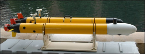
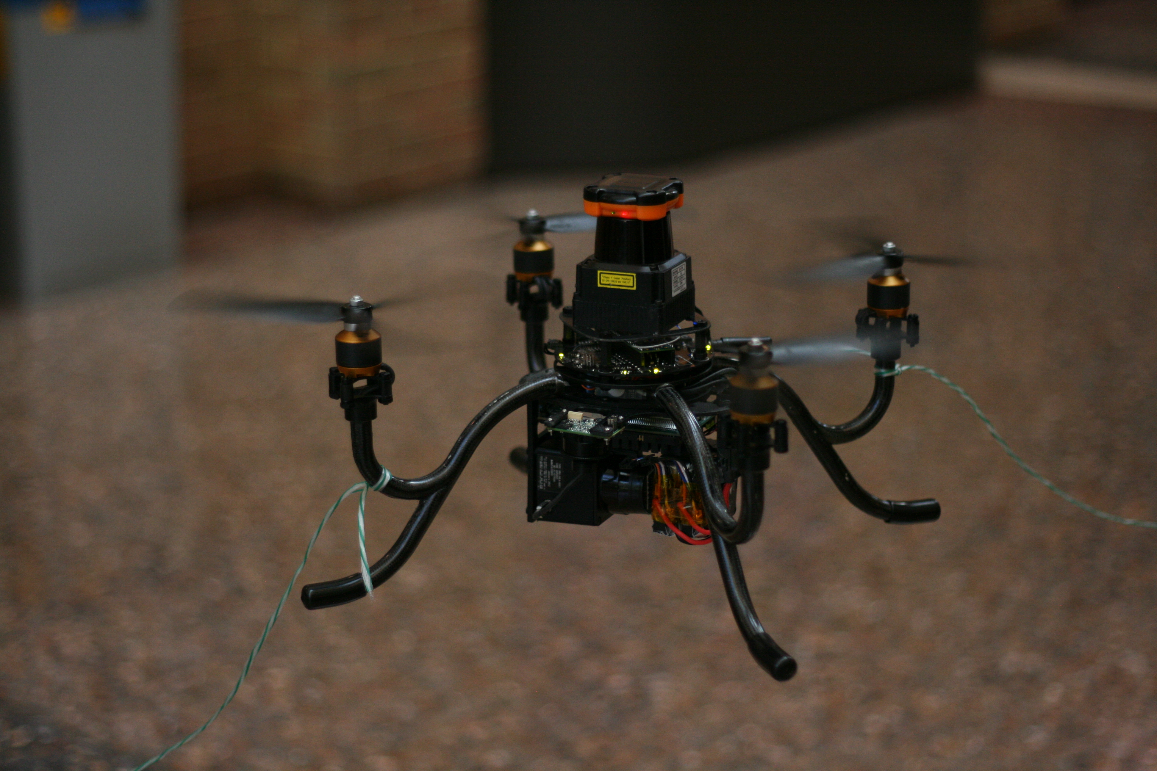
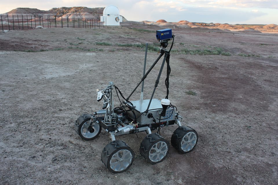
As shown in Figure 1 the proposed DG-SLAM algorithm can be used to build a map and simultaneously localize a vehicle moving in three dimensional space in a variety of environments.
Refer to caption
Refer to caption
Refer to caption
Figure 1: UAVs, terrestrial robots, submersibles. Credit: MAAV (http://www.maavumich.org), MRover (http://www.umrover.org), PeRL (http://robots.engin.umich.edu).

3 Notation

We consider the simultaneous mapping and localization problem in three dimensions. First let β„±asubscriptβ„±π‘Ž\mathcal{F}_{a} and β„±bsubscriptℱ𝑏\mathcal{F}_{b} denote the body-fixed frame of the robot and the datum frame, respectively, as shown in FigureΒ 2. The goal is to estimate the pose of the robot and the landmark positions, relative to the datum frame. Let rβ†’β†’π‘Ÿ{\underrightarrow{{r}}} denote the position of the center of mass of the vehicle relative to the origin of the datum frame. Also, let pβ†’isuperscript→𝑝𝑖{\underrightarrow{{p}}}^{i}, i∈{1,…,β„“}𝑖1…ℓi\in\{1,\ldots,\ell\} denote the position of landmark i𝑖i relative to the origin of the datum frame. Vectors rβ†’β†’π‘Ÿ{\underrightarrow{{r}}} and pβ†’isuperscript→𝑝𝑖{\underrightarrow{{p}}}^{i} may be resolved in any reference frame. For example, the representation of rβ†’β†’π‘Ÿ{\underrightarrow{{r}}} and pβ†’isuperscript→𝑝𝑖{\underrightarrow{{p}}}^{i} in β„±asubscriptβ„±π‘Ž\mathcal{F}_{a} is denoted 𝐫𝐚subscript𝐫𝐚\mbf{r}_{a} and 𝐩𝐚𝐒subscriptsuperscript𝐩𝐒𝐚\mbf{p}^{i}_{a}, where the subscript denotes the frame in which the vector has been resolved. An additional vector, denoted sβ†’isuperscript→𝑠𝑖{\underrightarrow{{s}}}^{i} denotes the position of landmark i𝑖i relative to the center of mass of the vehicle.

The pose of the robot is described by π—βˆˆπ’π„β€‹(πŸ‘)𝐗𝐒𝐄3\mbf{X}\in SE(3), where

S​E​(3)={[π‚π«πŸŽ1]βˆˆβ„4Γ—4|π‚βˆˆβ„πŸ‘Γ—πŸ‘,𝐂𝖳​𝐂=𝟏,det​(𝐂)=+𝟏,π«βˆˆβ„πŸ‘}.𝑆𝐸3conditional-setdelimited-[]𝐂𝐫01superscriptℝ44formulae-sequence𝐂superscriptℝ33formulae-sequencesuperscript𝐂𝖳𝐂1formulae-sequencedet𝐂1𝐫superscriptℝ3SE(3)=\left\{\left[\begin{array}[]{c c}\mbf{C}&\mbf{r}\\ \mbf{0}&1\end{array}\right]\in\mathbb{R}^{4\times 4}\ |\ \mbf{C}\in\mathbb{R}^{3\times 3},\mbf{C}^{\mathsf{T}}\mbf{C}=\mbf{1},\text{det}(\mbf{C})=+1,\mbf{r}\in\mathbb{R}^{3}\right\}.

Let

𝐗=[π‚π›πšπ–³π«πšπŸŽπŸ]βˆˆπ’π„β€‹(πŸ‘),𝐗delimited-[]superscriptsubscriptπ‚π›πšπ–³subscript𝐫𝐚01𝐒𝐄3\mbf{X}=\left[\begin{array}[]{c c}\mbf{C}_{ba}^{\mathsf{T}}&\mbf{r}_{a}\\ \mbf{0}&1\end{array}\right]\in SE(3), (1)

denote the true pose of the robot. The direction cosine matrix π‚π›πšsubscriptπ‚π›πš\mbf{C}_{ba} maps the coordinates of a vector resolved in β„±asubscriptβ„±π‘Ž\mathcal{F}_{a} to being resolved in β„±bsubscriptℱ𝑏\mathcal{F}_{b}. It is a representation of the attitude of the robot. The estimate of the pose of the robot is

𝐗^=[π‚πžπšπ–³π«^a𝟎1]∈S​E​(3),^𝐗delimited-[]superscriptsubscriptπ‚πžπšπ–³subscript^π«π‘Ž01𝑆𝐸3{\hat{\mbf{X}}}=\left[\begin{array}[]{c c}\mbf{C}_{ea}^{\mathsf{T}}&{\hat{\mbf{r}}}_{a}\\ \mbf{0}&1\end{array}\right]\in SE(3), (2)

where π‚πžπšsubscriptπ‚πžπš\mbf{C}_{ea} is the estimate of π‚π›πšsubscriptπ‚π›πš\mbf{C}_{ba} and 𝐫^asubscript^π«π‘Ž{\hat{\mbf{r}}}_{a} is the estimate of 𝐫𝐚subscript𝐫𝐚\mbf{r}_{a}. Similarly, the true map is denoted (𝐩𝐚𝟏,𝐩𝐚𝟐,…,π©πšβ„“)superscriptsubscript𝐩𝐚1superscriptsubscript𝐩𝐚2…superscriptsubscriptπ©πšβ„“(\mbf{p}_{a}^{1},\mbf{p}_{a}^{2},\ldots,\mbf{p}_{a}^{\ell}), while the map estimate is denoted (𝐩^a1,𝐩^a2,…,𝐩^aβ„“)superscriptsubscript^π©π‘Ž1superscriptsubscript^π©π‘Ž2…superscriptsubscript^π©π‘Žβ„“({\hat{\mbf{p}}}_{a}^{1},{\hat{\mbf{p}}}_{a}^{2},\ldots,{\hat{\mbf{p}}}_{a}^{\ell}).

Refer to caption
Figure 2: Vehicle, landmarks, and reference frames.

4 Differential Geometric SLAM Formulation

The following measurements are assumed available: (1) angular velocity, 𝝎bysuperscriptsubscriptπŽπ‘π‘¦{\bm{\omega}}_{b}^{y}, (2) velocity, 𝐯𝐛𝐲superscriptsubscript𝐯𝐛𝐲\mbf{v}_{b}^{y}, and (3) the position of each landmark relative to the robot, 𝐬𝐛𝐒,𝐲superscriptsubscript𝐬𝐛𝐒𝐲\mbf{s}_{b}^{i,y}. All measurements are taken in the body frame of the vehicle β„±bsubscriptℱ𝑏\mathcal{F}_{b}. For the purpose of the DG-SLAM formulation and the stability proof, noise and bias associated with measurements is assumed zero.

The proposed filter takes the following form:

𝐗^Λ™Λ™^𝐗\displaystyle\dot{{\hat{\mbf{X}}}} =𝐗^​𝐀^,𝐀^=[𝝎^×𝐯^𝟎0],formulae-sequenceabsent^𝐗^𝐀^𝐀delimited-[]superscript^𝝎^𝐯00\displaystyle={\hat{\mbf{X}}}{\hat{\mbf{A}}},\ \ {\hat{\mbf{A}}}=\left[\begin{array}[]{c c}{\hat{\bm{\omega}}}^{\times}&{\hat{\mbf{v}}}\\ \mbf{0}&0\end{array}\right],
𝐩^Λ™isubscriptΛ™^𝐩𝑖\displaystyle\dot{{\hat{\mbf{p}}}}_{i} =π‚πžπšπ–³β€‹πœΆπ’,absentsuperscriptsubscriptπ‚πžπšπ–³subscript𝜢𝐒\displaystyle=\mbf{C}_{ea}^{\mathsf{T}}{\bm{\alpha}}_{i},

where

𝝎^^𝝎\displaystyle{\hat{\bm{\omega}}} =𝝎byβˆ’k1β€‹πž,absentsuperscriptsubscriptπŽπ‘π‘¦subscriptπ‘˜1𝐞\displaystyle={\bm{\omega}}_{b}^{y}-k_{1}\mbf{e},
𝐞𝐞\displaystyle\mbf{e} =12​(π‚π›πšβ€‹π‚πžπšπ–³βˆ’π‚πžπšβ€‹π‚π›πšπ–³) 𝗏,absent12superscriptsubscriptπ‚π›πšsuperscriptsubscriptπ‚πžπšπ–³subscriptπ‚πžπšsuperscriptsubscriptπ‚π›πšπ–³Β π—\displaystyle=\mbox{$\textstyle{\frac{1}{2}}$}(\mbf{C}_{ba}\mbf{C}_{ea}^{\mathsf{T}}-\mbf{C}_{ea}\mbf{C}_{ba}^{\mathsf{T}})^{\raisebox{-1.80835pt}{ \kern-3.01389pt\raisebox{1.80835pt}{\small$\mathsf{v}$}}},
𝐯^^𝐯\displaystyle{\hat{\mbf{v}}} =𝐯𝐛𝐲+(𝝎^βˆ’πŽπ›π²)Γ—β€‹π‚πžπšβ€‹π«^𝐚+π€πŸβ€‹βˆ‘π’=πŸβ„“π¬~π’βˆ’π€πŸ‘β€‹(π‚πžπšβ€‹π«^𝐚+π¬π›πŸ,𝐲),absentsuperscriptsubscript𝐯𝐛𝐲superscript^𝝎superscriptsubscriptπŽπ›π²subscriptπ‚πžπšsubscript^𝐫𝐚subscript𝐀2superscriptsubscript𝐒1β„“superscript~𝐬𝐒subscript𝐀3subscriptπ‚πžπšsubscript^𝐫𝐚superscriptsubscript𝐬𝐛1𝐲\displaystyle=\mbf{v}_{b}^{y}+({\hat{\bm{\omega}}}-{\bm{\omega}}_{b}^{y})^{\times}\mbf{C}_{ea}{\hat{\mbf{r}}}_{a}+k_{2}\sum_{i=1}^{\ell}{\tilde{\mbf{s}}}^{i}-k_{3}(\mbf{C}_{ea}{\hat{\mbf{r}}}_{a}+\mbf{s}_{b}^{1,y}),
𝜢isubscriptπœΆπ‘–\displaystyle{\bm{\alpha}}_{i} =(𝝎^βˆ’πŽby)Γ—β€‹π‚πžπšβ€‹π©^πšπ’βˆ’π€πŸβ€‹π¬~𝐒,absentsuperscript^𝝎superscriptsubscriptπŽπ‘π‘¦subscriptπ‚πžπšsuperscriptsubscript^𝐩𝐚𝐒subscript𝐀2superscript~𝐬𝐒\displaystyle=({\hat{\bm{\omega}}}-{\bm{\omega}}_{b}^{y})^{\times}\mbf{C}_{ea}{\hat{\mbf{p}}}_{a}^{i}-k_{2}{\tilde{\mbf{s}}}^{i},

and 𝐬~i=π‚πžπšβ€‹(𝐩^πšπ’βˆ’π«^𝐚)βˆ’π¬π›π’,𝐲superscript~𝐬𝑖subscriptπ‚πžπšsuperscriptsubscript^𝐩𝐚𝐒subscript^𝐫𝐚superscriptsubscript𝐬𝐛𝐒𝐲{\tilde{\mbf{s}}}^{i}=\mbf{C}_{ea}({\hat{\mbf{p}}}_{a}^{i}-{\hat{\mbf{r}}}_{a})-\mbf{s}_{b}^{i,y} is the innovation, which incorporates the error in the map and the pose.

5 Stability Results

By employing the Lyapunov function (candidate),

V​(𝐗~,𝐩~a1,…,𝐩~aβ„“)=12β€‹β€–πŸβˆ’π—~β€–π–₯𝟐+βˆ‘π’=πŸβ„“β€–π©~πšπ’β€–πŸπŸ,𝑉~𝐗superscriptsubscript~π©π‘Ž1…superscriptsubscript~π©π‘Žβ„“12superscriptsubscriptnorm1~𝐗π–₯2superscriptsubscript𝐒1β„“superscriptsubscriptnormsuperscriptsubscript~𝐩𝐚𝐒22V({\tilde{\mbf{X}}},{\tilde{\mbf{p}}}_{a}^{1},\ldots,{\tilde{\mbf{p}}}_{a}^{\ell})=\mbox{$\textstyle{\frac{1}{2}}$}||\mbf{1}-{\tilde{\mbf{X}}}||_{\mathsf{F}}^{2}+\sum_{i=1}^{\ell}||{\tilde{\mbf{p}}}_{a}^{i}||_{2}^{2},

it can be shown that 𝐗~β†’πŸβ†’~𝐗1{\tilde{\mbf{X}}}\rightarrow\mbf{1} and 𝐩~aiβ†’πŸŽβ†’superscriptsubscript~π©π‘Žπ‘–0{\tilde{\mbf{p}}}_{a}^{i}\rightarrow\mbf{0} as tβ†’βˆžβ†’π‘‘t\rightarrow\infty, where 𝐗~=𝐗^β€‹π—βˆ’πŸ~𝐗^𝐗superscript𝐗1{\tilde{\mbf{X}}}={\hat{\mbf{X}}}\mbf{X}^{-1} denotes the error in the pose, and 𝐩~ai=π‚πžπšβ€‹π©^πšπ’βˆ’π‚π›πšβ€‹π©πšπ’superscriptsubscript~π©π‘Žπ‘–subscriptπ‚πžπšsuperscriptsubscript^𝐩𝐚𝐒subscriptπ‚π›πšsuperscriptsubscript𝐩𝐚𝐒{\tilde{\mbf{p}}}_{a}^{i}=\mbf{C}_{ea}{\hat{\mbf{p}}}_{a}^{i}-\mbf{C}_{ba}\mbf{p}_{a}^{i} denotes the error in the map. In the proof, it is assumed that π‚π›πšsubscriptπ‚π›πš\mbf{C}_{ba} is known, however this is not true in practise. A similar problem occurs in similar S​O​(3)𝑆𝑂3SO(3) and S​E​(3)𝑆𝐸3SE(3) filters [3, 4]. In the works of [3, 4] a geometric approximation of π‚π›πšsubscriptπ‚π›πš\mbf{C}_{ba}, π‚π›πšπ²=π‚π›πšπ²β€‹(𝐬𝐛𝐒,𝐲,𝐬𝐚𝐒)superscriptsubscriptπ‚π›πšπ²superscriptsubscriptπ‚π›πšπ²superscriptsubscript𝐬𝐛𝐒𝐲superscriptsubscript𝐬𝐚𝐒\mbf{C}_{ba}^{y}=\mbf{C}_{ba}^{y}(\mbf{s}_{b}^{i,y},\mbf{s}_{a}^{i}), is constructed from measurements and used in place of π‚π›πšsubscriptπ‚π›πš\mbf{C}_{ba}. In the proposed algorithm, π‚π›πšπ²superscriptsubscriptπ‚π›πšπ²\mbf{C}_{ba}^{y} is constructed from landmark measurements and the estimated landmark positions (i.e., π‚π›πšπ²=π‚π›πšπ²β€‹(𝐬𝐛𝐒,𝐲,𝐩^πšπ’βˆ’π«^𝐚)superscriptsubscriptπ‚π›πšπ²superscriptsubscriptπ‚π›πšπ²superscriptsubscript𝐬𝐛𝐒𝐲superscriptsubscript^𝐩𝐚𝐒subscript^𝐫𝐚\mbf{C}_{ba}^{y}=\mbf{C}_{ba}^{y}(\mbf{s}_{b}^{i,y},{\hat{\mbf{p}}}_{a}^{i}-{\hat{\mbf{r}}}_{a})). When using π‚π›πšπ²β€‹(𝐬𝐛𝐒,𝐲,𝐩^πšπ’βˆ’π«^𝐚)superscriptsubscriptπ‚π›πšπ²superscriptsubscript𝐬𝐛𝐒𝐲subscriptsuperscript^𝐩𝐒𝐚subscript^𝐫𝐚\mbf{C}_{ba}^{y}(\mbf{s}_{b}^{i,y},{\hat{\mbf{p}}}^{i}_{a}-{\hat{\mbf{r}}}_{a}), the map estimate does not converge to the true map resolved in β„±asubscriptβ„±π‘Ž\mathcal{F}_{a}. However, the estimated positions of the landmarks relative to the estimated pose of the robot converges to their true counterparts. This is to be expected, since the global SLAM problem is unobservable unless at least two landmarks positions are known [5].

6 Simulation Results

The DG-SLAM algorithm is employed in simulation. Although the stability proof assumes no noise, to assess robustness of the proposed DG-SLAM algorithm, noise has been added to the angular velocity, velocity, and vector measurements in the simulation. The results of the simulation can be found in Figures 3 and 4.

Refer to caption
(a) t=0𝑑0t=0 (s𝑠s)
Refer to caption
(b) t=5𝑑5t=5 (s𝑠s)
Refer to caption
(c) t=10𝑑10t=10 (s𝑠s)
Refer to caption
(d) t=20𝑑20t=20 (s𝑠s)
Figure 3: Visualization of SLAM algorithm. The blue diamonds denote the true positions of the landmarks. The orange markers denote the estimated landmark positions. The blue and orange boxes denote the true and estimated pose of the robot, respectively. During an initial period of 5 seconds the pose and map estimates rapidly converge towards the true pose and map. After 20 seconds the errors in the pose and map estimates have approached zero.
Refer to caption
Refer to caption
Refer to caption
Figure 4: Simulation results. The error in the pose of the robot as well as the map approaches zero.

7 Conclusions

The proposed SLAM algorithm is based on differential geometric principles and is similar to S​O​(3)𝑆𝑂3SO(3) and S​E​(3)𝑆𝐸3SE(3) estimators found in the literature. The algorithm requires no matrix inversions making it suitable for large scale implementation. Moreover, the filter is guaranteed asymptotically stable, assuming no measurement noise, no bias, and π‚π›πšsubscriptπ‚π›πš\mbf{C}_{ba} is known.

References

  • [1] Thrun, S., Burgard, W., and Fox, D., Probabilistic Robotics, MIT press, 2005.
  • [2] Aulinas, J., Petillot, Y.Β R., Salvi, J., and LladΓ³, X., β€œThe SLAM Problem: A Survey.” Proceedings of the 11th International Conference of the Catalan Association for Artificial Intelligence, Spain, 22–24 October, 2008.
  • [3] Mahony, R., Hamel, T., and Pflimlin, J.-M., β€œNonlinear Complementary Filters on the Special Orthogonal Group,” IEEE Transactions on Automatic Control, Vol.Β 53, No.Β 5, 2008, pp.Β 1203–1218.
  • [4] Baldwin, G., Mahony, R., Trumpf, J., Hamel, T., and Cheviron, T., β€œComplementary filter design on the Special Euclidean group SE (3),” Proceedings of the European Control Conference, Kos, Greece, 2–5 July, 2007.
  • [5] Wang, Z., Simultaneous Localization and Mapping: Exactly Sparse Information Filters, Vol.Β 3, World Scientific, 2011.