Localization length calculations in alternating metamaterial-birefringent disordered layered stacks
Abstract
A detailed theoretical and numerical analysis of the localization length in alternating metamaterial-birefringent random layered stacks, under uncorrelated thickness-disorder, has been performed. Similar structures have recently been reported to suppress the Brewster delocalization for -polarized light, when ”standard” isotropic layers (with positive index of refraction) are considered instead of metamaterial layers, providing a generic means to produce polarization-insensitive, broadband reflections. However, this enhancement of localization is valid for short wavelengths compared to the mean layer thickness . At higher wavelengths, we recover the Brewster anomalies for -polarized states impeding a remarkable localization of light. To achieve a better localization for a wider range of wavelengths, we replaced the conventional isotropic layers by negative-index metamaterials presenting low losses and constant index of refraction over the near-infrared range. As a result, our numerical calculations exhibit a linear dependence of the localization length with (in the region ) reducing the Brewster anomalies in more than two orders of magnitude with respect to the standard isotropic scheme at oblique incidence. This enhancement of localization is practically independent of the thickness disorder kind and is also held under weak refractive-index disorder.
pacs:
71.55.Jv,42.25.Lc,78.67.PtI Introduction
Broadband reflections from a disordered dielectric medium are a physical manifestation of the localization of light BE97 . It has been reported the design of such high-performance broadband mirrors with a broader reflection band than periodic systems with the same refractive indices ZH95 ; LI00 . If a stack system could be devised to effectively localize both - and -polarized light over all angles of incidence, it would provide a means to obtain polarization-insensitive, broadband reflections with potential applications that include waveguides and thermoelectric devices, among others FI98 . However, a fundamental problem arises due to the so-called Brewster delocalization AR90 ; DU97 ; LE11 , that is, the impossibility of achieving a total localization of light at certain oblique incidences for -polarization. The main reason is that the depth of penetration for states increases several orders of magnitude as compared with the depth of penetration of states SI88 . This is an important issue to take into account for potential polarization-insensitive broadband mirrors.
Recently, Jordan et al. JO13 reported a suppression of Brewster delocalization in stacks of alternating isotropic-birefringent random layers under uncorrelated thickness disorder. Stacks containing a mixture of positive uniaxial and negative uniaxial birefringent layers have been claimed as effective media to inhibit the Brewster delocalization for over all angles of incidence. This work was motivated by a previous analysis of the nonpolarizing reflections from birefringent guanine and isotropic cytoplasm multilayer structure found in some species of silvery fish JO12 . These authors mimic the guanine-cytoplasm structure in fish skin where there are two different types of birefringent crystal present with isotropic cytoplasm gaps and obtain a noticeable enhancement of localization. Nevertheless, as we will show briefly, this enhancement of localization for -polarized light is valid for short wavelengths compared to the mean layer thickness. At higher wavelengths, we recover the Brewster anomalies for states at oblique incidence, impeding a remarkable localization of light.
In order to achieve an improvement of localization, we propose a stack composed of alternating metamaterial-birefringent disordered layers where the isotropic layers possess a negative index of refraction (that is, we are dealing with left-handed (LH) isotropic media VE68 ; SM00 ). These artificial materials have been reported to resolve images beyond the diffraction limit PEN00 ; SMITH04 , act as an electromagnetic cloak LEO06 ; SCHU06 , enhance the quantum interference YANG08 or yield to slow light propagation PAPA09 . Moreover, recent research on LH metamaterials formed by hybrid metal-semiconductor nanowires PAN13 has described negative indices of refraction in the near-infrared with values of the real part well below -1 and extremely low losses (an order of magnitude better than present optical negative-index metamaterials). With this choice, we demonstrate a reduction of Brewster anomalies in more than two orders of magnitude with respect to the standard isotropic scheme at higher wavelengths, providing a means to obtain polarization-insensitive, broadband reflections in a wider wavelength region. Furthermore, this enhancement of localization is practically independent of the thickness disorder kind and is also held under weak refractive-index disorder.
The plan of the work is as follows. In Sec. II we carry out an exhaustive description of our system and the theoretical framework to derive an analytical expression for the localization length in the short-wavelength regime (that is, when the incident wavelength is less than the mean layer thickness ). A detailed numerical analysis concerning the localization length for two different disorder distributions (the Poisson-thickness disorder and the uniform-thickness distribution) will be performed in Sec. III. Two wavelength regions will be analyzed in detail: the previously mentioned short-wavelength regime and an intermediate-wavelength region () where, as we will show, the improvement of localization is more pronounced. For completeness, weak refractive-index disorder (with random variations in the indices of refraction of each layer) is also considered in our model. A set of analytical expressions for in the so-called intermediate-wavelength region, as a function of the wavelength and the incident angle , are also derived. Finally, we summarize our results in Sec. IV.
II System description and theoretical model
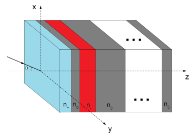
Our structure of interest is formed by a mixture of alternating uniaxial birefringent layers and LH isotropic media (see Fig. 1). For positive uniaxial layers, the corresponding refractive index vector is given by while for negative uniaxial . The principal axes of birefringent layers are aligned to and directions and the ratio of negative uniaxial to the total number of layers has been defined via the parameter . Each birefringent layer is sandwiched between two left-handed isotropic layers with negative index of refraction and the whole systems is embedded in a ”standard” isotropic media with positive refractive index . The following condition is hold to avoid critical angles, that is, to be sure that light is able to access all angles of incidence at each isotropic-birefringent interface in the stack. Light enters from the left at angle and propagates through axis.
In order to effectively improve the localization of light in such mixed structures, we need LH metamaterials with extremely low losses and constant values of the negative-index over a relatively wide spectrum. Such metamaterials have been recently reported by Paniagua-Dominguez et al. PAN13 and might operate in the near-infrared region (from 700 to 1900 nm in this case). As we will show in the next section, the enhancement of localization in our system is mainly achieved in a region where the incident wavelength satisfies the inequality , where corresponds to the mean layer thickness. Accordingly, our mixed disordered stack can adequately be tailored to operate in the near-infrared provided that .
Let us now perform a theoretical study of the localization length for both and states in such structures under uncorrelated thickness disorder. To this aim, we derive an expression for the transmission coefficient of the whole arrangement and then we use the standard definition of the localization length
| (1) |
where is the system length and the total number of layers. The angular brackets stand for averaging over the disorder. The theoretical method here employed is a non-perturbative approach based on the exact calculation of the Green’s function (GF) of an electromagnetic wave in a given electric permittivity profile AR91 . Once the GF of the layered structure is known, the transmission coefficient can be derived using the Fisher-Lee relation FI81 . This GF approach is compatible with the transfer matrix method and has been widely used to calculate the average density of states over a sample, the energy spectrum of elementary excitations CA97 or the characteristic barrier tunneling time GCB96 , among others.
In our Green’s function approach, the inverse of the transmission coefficient through our multilayer structure, , coincides with the diagonal elements of the resulting transfer matrix and can be derived via the following relation AR91
| (2) |
where corresponds to the so-called characteristic determinant
| (3) |
Here represents the total phase thickness accumulated by the incident wave along the whole sample, and is given by
| (4) |
where is the phase thickness of each individual layer. For our birefringent media, satisfy JO13
| (5) |
with the layer thickness and the corresponding indices of refraction of the positive or negative uniaxial layers
| (6) |
and
| (7) |
In our LH isotropic media, the parameters are calculated via the following expression
| (8) |
for both - and -polarized states. Notice that the phase thicknesses have negative sign in this case, due to the negativeness of the indices of refraction.
corresponds to the determinant of a tridiagonal matrix and satisfies the following recurrence relation
| (9) |
with the initial conditions
For we have
| (10) |
and
| (11) |
where the quantity symbolizes the Fresnel reflection amplitude of light propagating from region into region . In our case, these coefficients are given by the generalized isotropic-birefringent Fresnel relations JO13 ; AZ88
| (12) |
for polarization and
| (13) |
for -polarized states. As it is well-known, these reflection coefficients for polarization vanish at the generalized anisotropic Brewster angle OR14
| (14) |
If the Fresnel coefficients are small, one can easily find (after simple inspection of the recurrence relation Eq. (9)) that the parameter . Therefore, the determinant (and, consequently, the transmission coefficient ) may be calculated at arbitrary distribution of the layers thicknesses. Provided that our system presents thickness disorder only (so the reflection coefficients remain invariable along the averaging process) and for a large number of layers , we can write
| (15) |
where stands for the total number of positive or negative uniaxial layers, and the reflection coefficients are given by Eqs. (12) and (13), with the appropriate choice of uniaxial layer (that is, positive or negative) and incident polarization. After some trivial algebra, we obtain the following analytical expression for the localization length (see again Eq. (1))
| (16) |
where . Notice that, under the low-reflection assumption, our Eq. (16) is independent of the thickness disorder kind and the incident wavelength. We will analyze later the validity of this theoretical result for short wavelengths compared to the mean layer thickness, that is, .
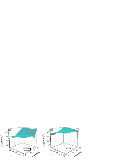
After simple inspection of Eq. (16), one observes that the Brewster anomalies for -polarized states only occur when (isotropic-positive stacks) or (isotropic-negative stacks). In such particular cases, the right-hand side of Eq. (16) becomes zero at resulting in the logarithmic divergence of the localization length and, consequently, in the delocalization of states. This result can be easily evidenced in Fig. 2 where we represent the inverse of the localization length for -polarization, (calculated via Eq.(16)) versus the parameter and the angle of incidence . Two different values of the positive birefringence have been selected (with our choice of the refractive index vectors, the following relation holds ). The index of refraction of the left-handed layers has been chosen to be . One observes that for real mixtures of positive and negative uniaxial layers JO13 (that is, when ) no Brewster anomalies occur. For higher birefringence parameters (see Fig. 2(b)) we obtain a smoothly varying landscape for . Consequently, as we increase the strength of the layers birefringence, the more localized states we achieve.
III Numerical results
In this section we present our numerical results concerning the localization length for two different disorder distributions, that is, the Poisson-thickness disorder and the uniform-thickness distribution (the latter also under weak refractive-index disorder). Two wavelength regions will be analyzed in detail: the short-wavelength regime (), where we will check the validity of our main theoretical result Eq. (16) and an intermediate-wavelength region () with an enhancement of localization up to two orders of magnitude with respect to standard isotropic layers.
III.1 Poisson-thickness disorder
Let us first consider the well-known Poisson thickness distribution for our disordered system, where the averaging process of is carried out via the following expression
| (17) |
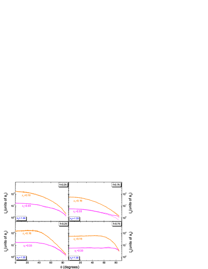
where, for each single realization, the numerical computation of the quantity is obtained via the exact recurrence relation Eq. (9). To this aim, we show in Fig. 3 the localization length versus the angle of incidence in disordered stacks with mixing ratios of (left column) and (right column) in the short-wavelength regime (). Dashed lines correspond to our theoretical results based on Eq. (16). One observes a good agreement between our numerical and theoretical results with an error of less than 5%. As can be noticed from Fig. 3, in the short-wavelength regime the localization length of states remains constant in a wide range of incident angles (about degrees for and degrees for ). As previously commented, higher values of the positive birefringence yields to an enhancement of localization. This is a manifestation of a total suppression of Brewster delocalization, in good agreement with recent numerical results JO13 .
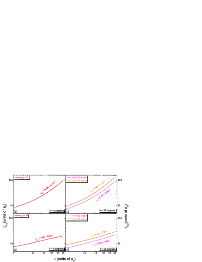
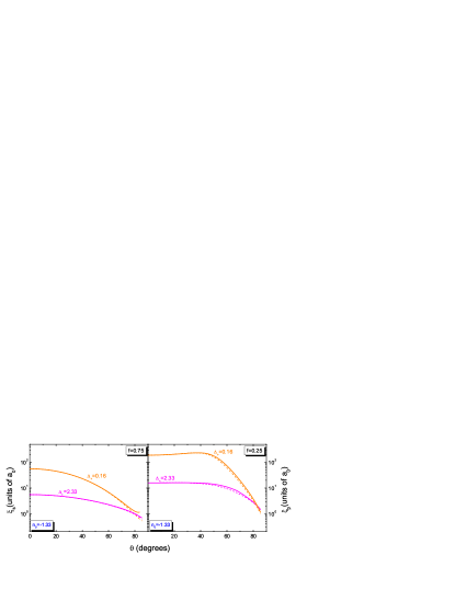
For higher wavelengths the situation is markedly different, as can be easily observed in Fig. 4. Here we represent our numerical calculations for the localization length as a function of the wavelength for two different angles of incidence, and degrees. Let us first concentrate on the top figures 4(a) and 4(b) where isotropic layers with index of refraction have been considered. The birefringence of positive layers has been chosen to be and the ratio . Solid lines symbolize our numerical results performed via Eq. (17). One notices that has a quadratic dependence on at higher wavelengths, a typical result for various disordered models and the subject of intensive ongoing research BA12 ; TO13 . Dotted lines correspond to the following numerically-deduced equations for the localization length as a function of the wavelength
| (18) |
| (19) |
where and () represents the localization length of () states in the limit of short wavelengths (see again Eq. (16)). In addition, stands for the average interfacial reflection coefficient in our system AR91 ; JO13 and is given by
| (20) |
An in-deep numerical analysis has been performed to derive Eqs. (18) and (19). To this aim, different layered stacks at different angles of incidence have been considered, and a detailed study of the coefficient characterizing the quadratic dependence on has been carried out. Notice that the results derived via Eqs. (18) and (19) are in good agreement with our numerical calculations for angles of incidence up to degrees. At higher angles of incidence (not shown in our figures) the deviation between numerical and analytical results is greater than 5%.
Let us now replace the ”standard” isotropic layers by left-handed isotropic metamaterials (this change, as previously mentioned, assumes that the index of refraction is now negative). As it was recently shown by our group for isotropic layered structures BA12 , this change of sign results in a significant modification of the transmission coefficient . As a consequence, the localization length presents a region of linear dependence with when the positions of the layer boundaries are randomly shifted with respect to ordered periodic values. The same behavior is found for LH isotropic-birefringent layered stacks.
The physical explanation for this effect is related to the vanishing of the total phase accumulated along the structure. This vanishing only occurs for stacks of alternating right-handed media (isotropic or birefringent) and left-handed isotropic layers, where the alternating phases possess opposite sign. Provided strong uncorrelated thickness disorder, the total phase accumulated over the whole structure is practically null. Thus, the transmission coefficient (which strongly depends on the total phase along the structure) has a smoother dependence on the frequency than the typical right-handed stacks, where the average of (see the denominator of Eq. (1)) gets the well-known dependence . In our case, this average has a linear dependence with the frequency (that is, the localization length is proportional to the wavelength ).
Our numerical calculations confirm this feature as can be noticed in Figs. 4(c) and 4(d). Solid lines symbolize our numerical calculations (Poisson thickness distribution, Eq. (17)) while dotted lines correspond to our numerically-deduced set of equations
| (21) |
| (22) |
After direct comparison of Figs. 4(c) and 4(d) (left-handed isotropic-birefringent stacks) with Figs. 4(a) and 4(b) (”standard” isotropic-birefringent stacks) one observes an enhancement of the localization for isotropic metamaterial structures at higher wavelengths, mainly due to a smoother dependence of the localization length with the incident wavelength .
III.2 Uniform-thickness disorder
Let us now study another type of thickness disorder where the arrangement of layers has random boundaries BA12 . For completeness, weak refractive-index disorder has also been included in our model, where we have randomly changed the indices of refraction of each layer via the following relations (isotropic layers) and (birefringent layers, either positive or negative). The superscripts indicate unperturbed refractive indices whereas the parameters are zero-mean independent random numbers within the interval . The strength of the disorder is measured by the parameter which has been chosen to be roughly a 2% of the corresponding unperturbed indices of refraction (that is, we assume weak refractive-index disorder).
Firstly, the short-wavelength regime will be considered. In Fig. 5 we show the localization length versus the angle of incidence in such disordered stacks with mixing ratios of (left column) and (right column) for . Dashed lines correspond to our theoretical result, Eq. (16). Even though this equation was derived for thickness-disorder only, a good agreement between our numerical and theoretical results is found, provided weak refractive-index disorder.
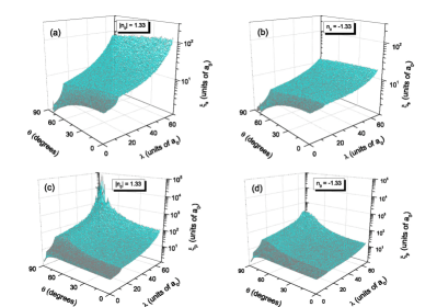
As we increase the incident wavelength, the behavior of the localization length is significantly different (as previously stated in the Poisson-thickness distribution). In Fig. 6 we represent three-dimensional plots of the localization length for a combined scheme of uniform-thickness and refractive-index disorder. Left-hand figures display the numerical calculations for isotropic-birefringent stacks with , whereas right-column graphs stand for our left-handed isotropic stacks with . In order to perform a reliable average of the logarithm of the transmission coefficient, , random configurations of our disordered stack have been considered in all cases. Once more, the birefringence of positive layers was and the ratio . It can be noticed that, at long wavelengths, a decrease of one order of magnitude for at normal incidence is achieved (compare Fig. 6(c) to 6(d)) and even up to two orders of magnitude at higher angles. Similar numerical results have been obtained taking into account uniform-thickness disorder alone (not shown in our figures). Consequently, under a strong uncorrelated positional disorder scheme, weak refractive-index disorder does not affect significatively the localization of light.
IV Discussion and Conclusions
A detailed theoretical and numerical analysis of the localization length, under uncorrelated thickness-disorder, in alternating metamaterial-birefringent random layered stacks has been performed. Our work was motivated by the recently reported suppression of Brewster delocalization in alternating isotropic-birefringent stacks JO12 , where Jordan et al. mimic the guanine-cytoplasm structure in fish skin formed by two different types of birefringent crystal present with isotropic cytoplasm gaps JO13 . Nevertheless, this enhancement of localization for -polarized states is achieved for short wavelengths (compared to the mean layer thickness ). At higher wavelengths, we recover the Brewster anomalies for states at oblique incidence, impeding a remarkable localization of light.
Our disordered metamaterial-birefringent stacks can effectively improve the localization of light in the so-called intermediate-wavelength region (in our case, ) up to two orders of magnitude with respect to the standard isotropic scheme at oblique incidence. This is mainly due to the smoother dependence of the localization length with the incident wavelength (linear dependence) in this particular region, unlike the well-known quadratic dependence in positive-index disordered stacks. Moreover, this enhancement of localization is practically independent of the thickness disorder kind and is also held under weak refractive-index disorder.
In order to reduce losses in our system (principally due to the presence of left-handed layers) we considered metamaterials with extremely low losses and constant values of the negative-index over the near-infrared region (from 700 to 1900 nm in this case) PAN13 . As shown in Sec. III, the predominant enhancement of localization in our system is achieved in the region . Accordingly, our mixed disordered stack can effectively be tailored to operate in the near-infrared provided that .
Our group consider that these metamaterial-birefringent disordered structures might provide great insight for the experimental design of polarization-insensitive, broadband reflectors.
Acknowledgements.
The authors would like to acknowledge Miguel Ortuño for helpful discussions. V. G. acknowledges partial support by FEDER and the Spanish DGI under Project No. FIS2010-16430.References
- (1) M. V. Berry and S. Klein, Eur. J. Phys. 18, 222 (1997).
- (2) D. Zhang, Z. Li, W. Hu and B. Cheng, Appl. Phys. Lett. 67, 2431 (1995).
- (3) H. Li, H. Chen and X. Qiu, Physica B: Condensed Matter 279, 164 (2000).
- (4) Y. Fink, J. N. Winn, S. Fan, C. Chen, M. Jurgen, J. D. Joannopoulos and E. L. Thomas, Science 282, 1679 (1998).
- (5) A. Aronov and V. Gasparian, Solid State Commun. 73, 61 (1990).
- (6) X. Du, D. Zhang, X. Zhang, B. Feng and D. Zhang, Phys. Rev. B 56, 28 (1997).
- (7) K. J. Lee and K. Kim, Opt. Express 19, 570 (2011).
- (8) J. E. Sipe, P. Sheng, B. S. White and M. H. Cohen, Phys. Rev. Lett. 60, 108 (1988).
- (9) T. M. Jordan, J. C. Partridge and N. W. Roberts, Phys. Rev. B 88, 041105(R) (2013).
- (10) T. M. Jordan, J. C. Partridge and N. W. Roberts, Nat. Photonics 6, 759 (2012).
- (11) V. G. Veselago, Sov. Phys. Usp. 102, 509 (1968).
- (12) D. R. Smith, W. J. Padilla, D. C. Vier, S. C. Nemat-Nasser and S. Schultz, Phys. Rev. Lett. 84, 4184 (2000).
- (13) J. B. Pendry, Phys. Rev. Lett. 85, 3966 (2000).
- (14) D. R. Smith, J. B. Pendry and M. C. K.Wiltshire, Science 305, 788 (2004).
- (15) U. Leonhardt, Science 312, 1777 (2006).
- (16) D. Schurig, J. Mock, B. Justice, S. Cummer, J. Pendry, A. Starr and D. Smith, Science 314, 977 (2006).
- (17) Y. Yang, J. Xu, H. Chen and S. Zhu, Phys. Rev. Lett. 100, 043601 (2008).
- (18) N. Papasimakis and N. Zheludev, Opt. Photonics News 20, 22 (2009).
- (19) R. Paniagua-Dominguez, D. R. Abujetas and J. A. Sanchez-Gil, Sci Rep. 3, 1507 (2013).
- (20) A. Aronov, V. Gasparian and U. Gummich, J. Phys.: Condens. Matter 3, 3023 (1991); V. M. Gasparian, Sov. Phys. Solid State 31, 266, (1989).
- (21) D. S. Fisher and P. A. Lee, Phys. Rev. B 23, 6851 (1981).
- (22) P. Carpena, V. Gasparian and M. Ortuño, Z. Phys. B 102, 425 (1997).
- (23) V. Gasparian, T. Christen and M. Buttiker, Phys. Rev. A 54, 4022 (1996).
- (24) R. M. Azzam and N. M. Bashara, Ellipsometry and Polarized Light (Elsevier, 1988), 269–363.
- (25) S. Orfanidis, Electromagnetic Waves and Antennas (online; accessed January 5 , 2014; http://www.ece.rutgers.edu/ orfanidi/ewa/).
- (26) O. del Barco and M. Ortuño, Phys. Rev. A 86, 023846 (2012).
- (27) E. J. Torres-Herrera, F. M. Izrailev and N. M. Makarov, New J. Phys. 15, 055014 (2013).