Nonlocal effective medium analysis in symmetric metal-dielectric multilayer metamaterials
Abstract
The optical nonlocality in symmetric metal-dielectric multilayer metamaterials is theoretically and experimentally investigated with respect to the TM-polarized incident light. A new nonlocal effective medium theory is derived from the transfer-matrix method to determine the nonlocal effective permittivity depending on both frequency and wave vector in the symmetric metal-dielectric multilayer stack. In contrast to the local effective medium theory, our proposed nonlocal effective medium theory can accurately predict the measured incident angle-dependent reflection spectra from the fabricated multilayer stack and provide nonlocal dispersion relations. Moreover, the bulk plasmon polaritons with large wave vectors supported in the multilayer stack are also investigated with the nonlocal effective medium theory through the analysis of dispersion relation and eigenmode.
pacs:
42.25.Bs, 78.20.Ci, 78.67.Pt, 81.05.ZxI Introduction
Metal-dielectric multilayer metamaterials have recently emerged into the focus of extensive exploration due to their anomalous electromagnetic properties in optical frequency range and the straightforward fabrication process. Metal-dielectric multilayer metamaterials with hyperbolic (or indefinite) dispersion have been demonstrated to realize a broad range of applications Poddubny2013NP , such as enhanced electromagnetic density of states Noginov2010OL ; Jacob2010APB , negative refraction Chui2006JP ; Hoffman2007NM ; Zhao2014AIP , deep-subwavelength imaging Jacob2006OE ; Liu2007Sci ; Zhang2008NM , spontaneous emission enhancement Jacob2012APL ; Iorsh2012PLA ; Lu2014NN , thermal emission engineering Guo2012APL , and anomalous indefinite cavities Yang2012NP . Furthermore, the metal-dielectric multilayer stack is also utilized to construct the epsilon-near-zero (ENZ) metamaterials, which is of great interests in many research areas, including radiation wavefront tailoring Alu2007PRB ; Sun2013PRB ; Sun2013APL , invisible cloaking Alu2005PRE ; Pendry2006Sci , displacement current insulation Engheta2007Sci ; Silveirinha2009PRL , optical nonlinearity enhancement Argyropoulos2012PRB , harmonic generation Vincenti2011PRA ; Ciattoni2012PRA , enhanced photonic density of states Vesseur2013PRL , and soliton excitations Rizza2011PRA . The electromagnetic properties of the metal-dielectric multilayer stack are simply characterized by the local effective medium theory (EMT) since the nanoscale multilayer period is much smaller than the electromagnetic wavelength. In fact, the variation of the electromagnetic field on the scale of the multilayer period will result in the spatial dispersion, leading to the optical nonlocality Elser2007APL , which has been studied in other types of metamaterials such as split-ring resonator arrays Belov2005PRE and nanorod structures Silveirinha2006PRE ; Belov2003PRB . Due to the strong optical nonlocality in the metal-dielectric multilayer stack, especially when the frequency of the electromagnetic field approaches to the ENZ position Sun2013OE , several extraordinary optical phenomena appear, such as the additional light waves Orlov2011PRB and complex eigenmodes Orlov2013OE , which cannot be predicted by the local EMT. In order to address this issue, the limitation of the local EMT has been studied recently Kidwai2012PRA , and several different nonlocal EMT models have been proposed, such as the field averaging algorithm confined to the lossless condition Chebykin2011PRB ; Chebykin2012PRB and the dispersion relation approximation limited to the normal incident light Gao2013APL .
In this work, the optical nonlocality is theoretically and experimentally studied in the symmetric metal-dielectric multilayer stack with respect to the TM-polarized incident light for different incident angles. The optical nonlocality for the TM-polarized incident light is much stronger than that for the TE-polarized light that we have studied previously Sun2014OE , due to the fact that the effective permittivity tensor for the TM-polarized light shows strong anisotropy. Here a new nonlocal EMT is derived based on the original definition of the effective permittivity through the transfer-matrix method Born1999 in order to analytically describe the variation of the electromagnetic field across the symmetric metal-dielectric multilayer stack with respect to both frequency and wave vector. It is demonstrated that the measured incident angle-dependent reflection spectra from the fabricated multilayer stack can be predicted accurately by the proposed nonlocal EMT, instead of the local EMT. Furthermore, the difference between the nonlocal effective permittivity and the local effective permittivity is also analyzed in detail, together with the ENZ position shift and the variation of iso-frequency contour (IFC) induced by the optical nonlocality. Moreover, the bulk plasmon polaritons (BPPs)Avrutsky2007PRB ; Sreekanth2013SR , a sort of highly confined optical modes with large wave vectors generated from the coupling of the surface plasmon polaritons (SPPs) propagating along the interfaces of the metal-dielectric multilayer stack, are also investigated with the nonlocal EMT through the analysis of dispersion relation and eigenmode.
II Development of Nonlocal Effective Medium Theory
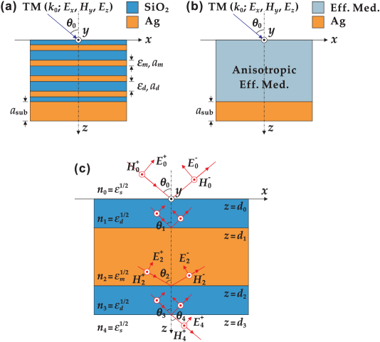
Figure 1(a) illustrates the schematic of the symmetric metal-dielectric multilayer stack composed of -pair periodic silver () and silica () layers on the top of a thick silver substrate. The - multilayer stack possesses a symmetric unit structure with one half-thickness layer on the top of the layer and the other at the bottom. The silver substrate acts as a mirror to block the transmission and enhance the reflection from the multilayer stack so that the optical nonlocality is only strongly related to the measured reflection spectra in experiments. The permittivity and the thickness of the layer and the layer are individually denoted as (, ) and (, ), while the thickness of the silver substrate is denoted as . Here the TM-polarized incident light propagating in the - plane with an arbitrary incident angle is considered. In general, the symmetric - multilayer stack can be regarded as a bulk homogenous and anisotropic effective medium on the top of the silver substrate as shown in Fig. 1(b). With respect to the TM-polarized light propagating in the - plane, the local anisotropic effective permittivity of the multilayer stack can be approximated by the local EMT as and . Clearly, the local effective permittivity is only a function of frequency, without considering the spatial dispersion caused by the optical nonlocality. However, previous studies show that the metal-dielectric multilayer stack possesses strong optical nonlocality, leading to the nonlocal effective permittivity that is not only related to the frequency but also to the wave vector.
In order to take into account the optical nonlocality, the nonlocal EMT based on the original definition of the effective permittivity is proposed and derived through the transfer-matrix method, where the - multilayer stack is considered as a one-dimensional photonic crystal structure. In the uniaxial multilayer stack, the nonlocal effective permittivity tensor of the stack can be presented as a diagonal matrix with non-zero diagonal components and , while the off-diagonal components are negligible. Furthermore, due to the symmetric and periodic property of the - multilayer stack, the nonlocal effective permittivity is independent of the number of layers. Therefore, only one symmetric unit cell embedded in a homogenous and isotropic surrounding medium is considered in the calculation of the nonlocal effective permittivity, as displayed in Fig. 1(c). For the TM-polarized incident light, the electric field in each layer can be presented as a linear combination of the forward propagating wave (along the positive -direction) and the backward propagating wave (along the negative -direction)
| (1) |
where represents the layer number shown in Fig. 1(c) and . Note that the factor in Eq. (1) is omitted since the wave vector along the interfaces is preserved across each layer. According to the boundary conditions, the electric fields across each interface are related via the transfer-matrix as
| (2) |
in which the transmission coefficient and the reflection coefficient are
| (3) |
and
| (4) |
with respect to the TM-polarized incident light. Furthermore, the phase variation of the electric field in each layer can be determined as
| (5) |
where the phase factor and are expressed as
| (6) |
and
| (7) |
Therefore, the nonlocal effective permittivity can be obtained based on the original definition of effective permittivity as
| (8) |
and
| (9) |
which are related to the amplitudes of the electric fields in Eqs. (2)–(4) and the phase factors in Eqs. (6)–(7). It is noted that according to the conservation of the wave vector across each layer, the nonlocal effective permittivity obtained from Eqs. (8)–(9) depends on both the frequency and the wave vector via (where the wave vector of free space is ). Therefore, both the frequency and the spatial dispersion are considered in the nonlocal EMT.
III Nonlocal EMT Analysis of Experimental Data
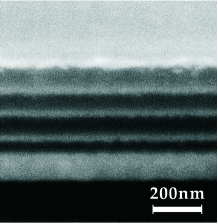
In order to demonstrate the effects from the optical nonlocality, the symmetric -pair - multilayer stack on the top of a thick silver substrate shown in Fig. 1(a) is then fabricated and the measured reflection spectra are compared with the nonlocal EMT analysis. The thickness of the layer and of the layer is designed to be and , respectively. The thickness of the silver substrate is which is thick enough to block the optical transmission in visible frequency region. The multilayer stack is deposited on top of silicon substrates with the electron-beam evaporation system, where is deposited at the rate of Å and is deposited at Å. Each material is individually deposited on a silicon substrate first to calibrate and optimize the deposition parameters. The optical constant of each material and the film thickness are characterized with the variable angle spectroscopic ellipsometry (VASE, J. A. Woollam Co. VB400/HS-190). The VASE measurements show that the optical constant of matches the standard data of Johnson and Christy Johnson1972PRB based on the fitting from a general oscillator model. The dielectric constant of is fitted from the Sellmeier dispersion relation. The VASE measured film thickness for each material also matches the thickness value for the set deposition parameters. Figure 2 shows the scanning electron microscope (SEM) picture of the cross section of the fabricated - multilayer stack on the top of the silver substrate, in which the focused ion beam (FIB) system (Helios Nanolab 600) is used to cut the cross section. Each deposited thin layer can be clearly seen, where the bright and the dark stripes individually correspond to the layers and the layers, together with the silver substrate at the bottom. The thickness of the deposited layers can be characterized with the VASE, and the measured averaged thickness for the layer, the layer, and the silver substrate is , , and , respectively.
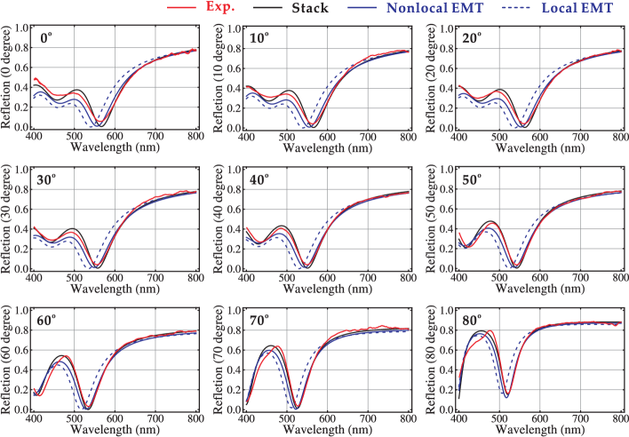
The reflection spectra of the symmetric - multilayer stack above the silver substrate are then measured under the TM-polarized light in the wavelength range from to , with respect to different angles of incidence from to with a variation of . The measured reflection spectra containing the information of optical nonlocality are compared with the theoretical reflection spectra calculated from the multilayer stack, the local EMT, and the nonlocal EMT at different angles of incidence, as shown in Fig. 3. It is clear that the theoretical reflection spectra obtained from the multilayer stack calculation (black curves) are coincident with the experimental reflection spectra (red curves). Meanwhile, the theoretical reflection spectra calculated from the nonlocal EMT (blue curves) is also very close to the experimental data, showing the locations of the reflection minimums accurately. However, without the consideration of optical nonlocality, the theoretical reflection spectra obtained from the local EMT (dashed-blue curves) deviate far away from the experimental reflection spectra with obvious blue shifts.
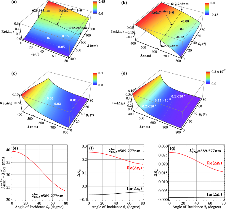
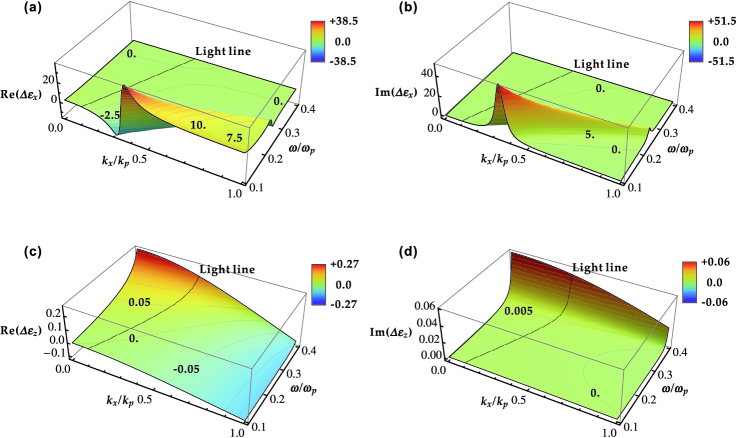
Furthermore, in order to indicate the effects of optical nonlocality on the effective permittivity, Figs. 4(a)–4(d) plot the differences between the nonlocal effective permittivity and the local effective permittivity defined as and for the -component and the -component of the effective permittivity, respectively. It is shown that the -component of the effective permittivity is more sensitive to the optical nonlocality, since the variation of is greater than the value of in both the real part and the imaginary part with respect to the variations of the wavelength and the angle of incidence. In addition, the variation of the ENZ wavelength associated with the optical nonlocality (nonlocal ENZ wavelength) that is determined as is also plotted as the black curves in Figs. 4(a) and 4(b), which indicate that the nonlocal ENZ wavelength varies from to as the angle of incidence changes from to . The difference between the nonlocal ENZ wavelength and the local ENZ wavelength is also illustrated in Fig. 4(e) as a function of the angle of incidence. The variation of the permittivity differences and at the local ENZ wavelength with respect to the angle of incidence are shown in Figs. 4(f) and 4(g), which reveal that the optical nonlocality has stronger influence on the -component of the effective permittivity than on the -component of the effective permittivity.
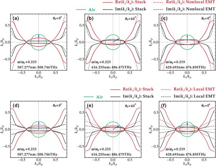
The iso-frequency contours (IFCs) based on both the nonlocal EMT and the local EMT can be obtained based on the nonlocal effective permittivity and the local effective permittivity,
| (10) |
and
| (11) |
The IFCs of the multilayer stack will also be calculated from the dispersion equation, where the multilayer stack is considered as a one-dimensional photonic crystal Elser2007APL
| (12) |
in which for the TM-polarized light. As displayed in Fig. 5, the IFCs calculated from the nonlocal EMT in Eq. (10) and the local EMT in Eq. (11) are compared with those obtained from the multilayer stack in Eq. (12) at three specific wavelengths: the local ENZ wavelength [Figs. 5(a) and 5(d)], the nonlocal ENZ wavelength associated with the angle of incidence [Figs. 5(b) and 5(e)], and the nonlocal ENZ wavelength related to the angle of incidence [Figs. 5(c) and 5(f)]. The IFCs based on the nonlocal EMT [dashed curves in Figs. 5(a)–5(c)] are almost the same as those of the multilayer stack (solid curves), especially in the area that the wave vector is confined in the light cone of the air (green circles). The deviation only occurs when the wave vector approaches to the boundary of the Brillouin zone, where the multilayer stack cannot just be regarded as a homogenous and anisotropic effective medium since the periodic property of the multilayer stack play important roles. On the contrary, the IFCs based on the local EMT [dashed curves in Figs. 5(d)–5(f)] are far away from the IFCs of the multilayer stack without considering the optical nonlocality. Finally, it is notable that during the calculation, the values of the wave vectors are normalized by the specified wave vector that is related to the plasma frequency .
IV Analysis of Dispersion Relation and Bulk Plasmon Mode
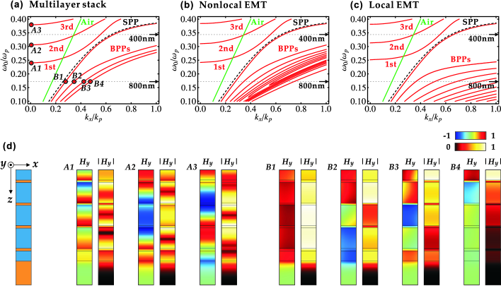
The TM-polarized incident light will excite the SPPs at the metal-dielectric interfaces of the multilayer stack when the wave vector extends beyond the light line of the free space. Moreover, due to the coupling of the SPPs between different multilayer interfaces, the BPPs with large wave vectors will be generated in the multilayer stack, which will strongly enhance the optical nonlocality. The enhanced optical nonlocality can be illustrated by the differences between the nonlocal effective permittivity and the local effective permittivity and with respect to the variations of the frequency and the wave vector, as shown in Fig. 6. Similar to the results in Figs. 4(a)–4(d), [Figs. 6(a) and 6(b)] is more sensitive to the optical nonlocality than [Figs. 6(c) and 6(d)] in both the real part and the imaginary part. Furthermore, the variation of the is greatly increased when the wave vector extends to the region below the light line of free space, i.e., , where the BPPs are excited in the metal-dielectric multilayer stack and propagate along the metal-dielectric interfaces in the -direction.
In order to understand the mechanism for the giant in the BPP region, the dispersion relations calculated from the multilayer stack in Eq. (12), the nonlocal EMT in Eq. (10) and the local EMT in Eq. (11) are investigated, as shown in Figs. 7(a), 7(b) and 7(c), respectively. The dispersion curves are separated by the light line of air (straight green line) into two regions. Above the light line (), the dispersion of the multilayer stack in Fig. 7(a) includes three branches, in which the first and the second branches (A1 and A2) located between the experimental wavelength range from to are related to the two minimums in the reflection spectra in Fig. 3, while the third branch (A3) is not observed in the reflection spectra since it is outside the experimental wavelength range. Below the light line (), the dispersion of the multilayer stack in Fig. 7(a) possesses another four branches (B1, B2, B3, and B4) that are below the dispersion of the SPP (dashed-black curve) calculated via , corresponding to four BPP modes associated with the four layers in the multilayer stack. Regarding to the dispersion relations calculated from the nonlocal EMT [Fig. 7(b)] and the local EMT [Fig. 7(c)], it is shown that the three branches above the light line are similar to those the multilayer stack in Fig. 7(a). The three branches in the dispersion relation from the nonlocal EMT in Fig. 7(b) are almost the same as those from the multilayer stack, but the three branches from the local EMT give slight blue shifts in Fig. 7(c). However, the dispersion relations in the BPP region below the light line calculated from the multilayer stack, the nonlocal EMT, and the local EMT are quite different. According to the EMT, the multilayer stack is regarded as a bulk homogenous and anisotropic effective medium so that there is no specific metal-dielectric interfaces inside the medium anymore during the procedure of averaging the electromagnetic field across each periodic structure. Therefore, the BPP modes supported in either the nonlocal medium in Fig. 7(b) or the local effective medium in Fig. 7(c) are determined by the interference of the SPPs between the two boundaries of the effective medium and therefore there are many more branches shown in the BPP region. With the consideration of the spatial dispersion related to the optical nonlocality in the nonlocal EMT, the first four branches in the BPP region in the dispersion relation in Fig. 7(b) are almost identical with the four branches related to the BPP modes in the dispersion relation of the multilayer stack in Fig. 7(a). On the contrary, the dispersion relation from the local EMT does not perform such properties in the BPP region, implying that the local EMT is not accurate to describe the BPP mode dispersion. To further explore the dispersion relation of the multilayer stack, Fig.7(d) illustrates the eigenmodes of the electromagnetic field associated with the seven branches of the dispersion relation in Fig. 7(a), in terms of the distributions of both the magnetic field amplitude and the magnetic field intensity . It is clear that the first three eigenmodes (A1, A2, and A3) above the light line behaves as propagating modes along the -direction in the multilayer stack across through the whole multilayer stack. On the other hand, the four BPP eigenmodes (B1, B2, B3, and B4) in the multilayer stack have the localized electromagnetic fields along the interfaces of the layers and the layers due to the coupling of the SPP modes.
V Conclusions
A nonlocal EMT has been derived based on the original definition of the effective permittivity through the transfer-matrix method in order to study the optical nonlocality in the symmetric metal-dielectric multilayer stack with respect to the TM-polarized incident light for different incident angles. Instead of the local EMT, the nonlocal EMT can accurately predict the measured incident angle-dependent reflection spectra from the fabricated multilayer stack due to the consideration of nonlocal effective permittivity. The nonlocal EMT not only reveals the difference between the nonlocal effective permittivity and the local effective permittivity but also the variation of IFCs induced by the optical nonlocality. Furthermore, the BPP modes with large wave vectors enhanced by the optical nonlocality can also be characterized with the nonlocal EMT.
Acknowledgments
The authors acknowledge the support from the University of Missouri Interdisciplinary Intercampus Research Program, the Ralph E. Powe Junior Faculty Enhancement Award, and the National Science Foundation under grant CBET-1402743. This work was performed, in part, at the Center for Integrated Nanotechnologies, an Office of Science User Facility operated for the U.S. Department of Energy (DOE) Office of Science. Sandia National Laboratories is a multi-program laboratory managed and operated by Sandia Corporation, a wholly owned subsidiary of Lockheed Martin Corporation, for the U.S. Department of Energy’s National Nuclear Security Administration under contract DE-AC04-94AL85000.
References
- (1) A. Poddubny, I. Iorsh, P. Belov, and Y. Kivshar, Nat. Photonics 7, 958 (2013).
- (2) M. A. Noginov, H. Li, Y. A. Barnakov, D. Dryden, G. Nataraj, G. Zhu, C. E. Bonner, M. Mayy, Z. Jacob, and E. E. Narimanov, Opt. Lett. 35, 1863 (2010).
- (3) Z. Jacob, J. Kim, G. Naik, A. Boltasseva, E. Narimanov, and V. Shalaev, Appl. Phys. B 100, 215 (2010).
- (4) S. T. Chui, C. T. Chan, and Z. F. Lin, J. Phys.: Condens. Matter 18, L89 (2006).
- (5) A. J. Hoffman, L. Alekseyev, S. S. Howard, K. J. Franz, D. Wasserman, V. A. Podolskiy, E. E. Narimanov, D. L. Sivco, and C. Gmachl, Nat. Mater. 6, 946 (2007).
- (6) J. Zhao, J. Gao, Y. Deng, H. Liu, and X. Wang, AIP Adv. 4, 047127 (2014).
- (7) Z. Jacob, L. V. Alekseyev, and E. Narimanov, Opt. Express 14, 8247 (2006).
- (8) Z. Liu, H. Lee, Y. Xiong, C. Sun, and X. Zhang, Science 315, 1686 (2007).
- (9) X. Zhang and Z. Liu, Nat. Mater. 7, 435 (2008).
- (10) Z. Jacob, I. I. Smolyaninov, and E. E. Narimanov, Appl. Phys. Lett. 100, 181105 (2012).
- (11) I. Iorsh, A. Poddubny, A. Orlov, P. Belov, and Y. S. Kivshar, Phys. Lett. A. 376, 185 (2012).
- (12) D. Lu, J. J. Kan, E. E. Fullerton, and Z. Liu, Nat. Nanotechnol. 9, 48 (2014).
- (13) Y. Guo, C. L. Cortes, S. Molesky, and Z. Jacob, Appl. Phys. Lett. 101, 131106 (2012).
- (14) X. Yang, J. Yao, J. Rho, X. Yin, and X. Zhang, Nat. Photonics 6, 450 (2012).
- (15) A. Alù, M. G. Silveirinha, A. Salandrino, and N. Engheta, Phys. Rev. B 75, 155410 (2007).
- (16) L. Sun, J. Gao, and X. Yang, Phys. Rev. B 87, 165134 (2013).
- (17) L. Sun, X. Yang, and J. Gao, Appl. Phys. Lett. 103, 201109 (2013).
- (18) A. Alù and N. Engheta, Phys. Rev. E 72, 016623 (2005).
- (19) J. B. Pendry, D. Schurig, and D. R. Smith, Science 312, 1780 (2006).
- (20) N. Engheta, Science 317, 1698 (2007).
- (21) M. Silveirinha and N. Engheta, Phys. Rev. Lett. 102, 103902 (2009).
- (22) C. Argyropoulos, P.-Y. Chen, G. D’Aguanno, N. Engheta, and A. Alù, Phys. Rev. B 85, 045129 (2012).
- (23) M. A. Vincenti, D. de Ceglia, A. Ciattoni, and M. Scalora, Phys. Rev. A 84, 063826 (2011).
- (24) A. Ciattoni and E. Spinozzi, Phys. Rev. A 85, 043806 (2012).
- (25) E. J. R. Vesseur, T. Coenen, H. Caglayan, N. Engheta, and A. Polman, Phys. Rev. Lett. 110, 013902 (2013).
- (26) C. Rizza, A. Ciattoni, and E. Palange, Phys. Rev. A 83, 053805 (2011).
- (27) J. Elser, V. A. Podolskiy, I. Salakhutdinov, and I. Avrutsky, Appl. Phys. Lett. 90, 191109 (2007).
- (28) P. A. Belov and C. R. Simovski, Phys. Rev. E 72, 026615 (2005).
- (29) M. Silveirinha, Phys. Rev. E 73, 046612 (2006).
- (30) P. A. Belov, R. Marques, S. I. Maslovski, I. S. Nefedov, M. Silveirinha, C. R. Simovski, and S. A. Tretyakov, Phys. Rev. B 67, 113103 (2003).
- (31) L. Sun, J. Gao, and X. Yang, Opt. Express 21, 21542 (2013).
- (32) A. A. Orlov, P. M. Voroshilov, P. A. Belov, and Y. S. Kivshar, Phys. Rev. B 84, 045424 (2011).
- (33) A. Orlov, I. Iorsh, P. Belov, and Y. Kivshar, Opt. Express 21, 1593 (2013).
- (34) O. Kidwai, S. V. Zhukovsky, and J. E. Sipe, Phys. Rev. A 85, 053842 (2012).
- (35) A. V. Chebykin, A. A. Orlov, A. V. Vozianova, S. I. Maslovski, Yu. S. Kivshar, and P. A. Belov, Phys. Rev. B 84, 115438 (2011).
- (36) A. V. Chebykin, A. A. Orlov, C. R. Simovski, Y. S. Kivshar, and P. A. Belov, Phys. Rev. B 86, 115420 (2012).
- (37) J. Gao, L. Sun, H. Deng, C. J. Mathai, S. Gangopadhyay, and X. Yang, Appl. Phys. Lett. 103, 051111 (2013).
- (38) L. Sun, F. Cheng, C. J. Mathai, S. Gangopadhyay, J. Gao, and X. Yang, Opt. Express 22, 22974 (2014).
- (39) M. Born and E. Wolf, Principles of optics: electromagnetic theory of propagation, interference and diffraction of light (Cambridge University Press 1999).
- (40) I. Avrutsky, I. Salakhutdinov, J. Elser, and V. Podolskiy, Phys. Rev. B 75, 241402(R) (2007).
- (41) K. V. Sreekanth, A. De Luca, and G. Strangi, Sci. Rep. 3, 3291 (2013).
- (42) P. B. Johnson and R. W. Christy, Phys. Rev. B 6, 4370 (1972).
Figure Captions
FIG. 1. (Color online) (a) Schematic of the symmetric and periodic - multilayer stack on the top of the silver substrate. (b) Schematic of the homogeneous and anisotropic effective medium on the silver substrate. (c) Schematic of the symmetric unit cell of the - multilayer stack with respect to the TM-polarized incident light across each layer.
FIG. 2. (Color online) The SEM picture of the cross section of the fabricated - multilayer stack on the silver substrate.
FIG. 3. (Color online) The measured reflection spectra from the - multilayer stack (black curves), the calculated reflection spectra based on the multilayer stack (red curves), the nonlocal EMT (blue curves) and the local EMT (dashed-blue curves) at different angles of incidence from to over the wavelength range from to .
FIG. 4. (Color online) The differences between the nonlocal effective permittivity and the local effective permittivity for (a) , (b) , (c) , and (d) , with respect to the variations of the angle of incidence and the wavelength. (e) The differences between the nonlocal ENZ wavelength and the local ENZ wavelength as a function of the angle of incidence. The differences between the nonlocal effective permittivity and the local effective permittivity with respect to the angle of incidence at the local ENZ wavelength for (f) the -component and (g) the -component .
FIG. 5. (Color online) The comparison between the IFCs of the multilayer stack (solid curves) and the IFCs based on the nonlocal EMT (dashed curves) at (a) the local ENZ wavelength , (b) the nonlocal ENZ wavelength associated with the angle of incidence , and (c) the nonlocal ENZ wavelength related to the angle of incidence . The comparison between the IFCs of the multilayer stack (solid curves) and the IFCs based on the local EMT (dashed curves) at (c) the local ENZ wavelength , (d) the nonlocal ENZ wavelength associated with the angle of incidence , and (e) the nonlocal ENZ wavelength related to the angle of incidence .
FIG. 6. (Color online) The differences between the nonlocal effective permittivity and the local effective permittivity for (a) , (b) , (c) , and (d) as a function of the wave vector and the frequency .
FIG. 7. (Color online) The dispersion relation calculated from (a) the multilayer stack, (b) the nonlocal EMT, and (c) the local EMT. (d) The eigenmodes of the electromagnetic field in the multilayer stack with respect to the dispersion relation (a) in terms of the distributions of both the magnetic field amplitude and the magnetic field intensity .