Phase formation, thermal stability and magnetic moment of cobalt nitride thin films
Abstract
Cobalt nitride (Co-N) thin films prepared using a reactive magnetron sputtering process by varying the relative nitrogen gas flow () are studied in this work. As increases, Co(N), , Co3N and CoN phases are formed. An incremental increase in , after emergence of phase at =10, results in a continuous expansion in the lattice constant () of . For =30, maximizes and becomes comparable to its theoretical value. An expansion in of , results in an enhancement of magnetic moment, to the extent that it becomes even larger than pure Co. Though such higher (than pure metal) magnetic moment for Fe4N thin films have been theoretically predicted and evidenced experimentally, higher (than pure Co) magnetic moment are evidenced in this work and explained in terms of large-volume high-moment model for tetra metal nitrides.
Nitrides of 3 magnetic transition metals (TM=Cr,Mn,Fe,Co,Ni) are an interesting class of materials for applications in magnetic devices. With inclusion N atoms (), TM become chemically inert and since they preserve the metallic character of the host metal, their structural and magnetic properties are superior. For example, a higher-than-Fe magnetic moment for iron nitrides ( Ji et al. (2011) and Ito et al. (2011a); Atiq et al. (2008)), has been the driving force for the intense research work in this system. Bhattacharyya (2015); Tayal et al. (2014) Specially, in case of tetra TM nitrides (), such enhanced magnetic moment is caused by a volume expansion (compared to a hypothetical metal). Imai, Sohma, and Suemasu (2014) All share a common structure, in which metal atoms are arranged in the positions and N atoms occupy the body centered positions. Such incorporation of N atoms results in an expansion of the lattice. Matar, Houari, and Belkhir (2007)
Compared to the Fe-N system, the Co-N system has been relatively less explored. Matsuoka, Ono, and Inukai (1986); Oda, Yoshio, and Oda (1987); Suzuki et al. (1995); Asahara et al. (2001); Fang et al. (2004); Jia et al. (2008); Paduani (2008); Houari, Matar, and Belkhir (2010); Imai, Takahashi, and Kumagai (2010) Recent theoretical calculations predicted that the spin polarization ratio for is even higher than that of . Takahashi, Imai, and Kumagai (2011) This has lead to somewhat renowned interests in the Co-N system both theoretically and experimentally. Ito et al. (2011b, c); Bhandari et al. (2012); Lourenço et al. (2014); Liu et al. (2014); Silva et al. (2014, 2015) Though theoretical studies predict that under large-volume high-moment approach, the magnetic moment of can be larger than Co, Matar, Houari, and Belkhir (2007) experimental results always find a value much smaller than pure Co, for thin films. Ito et al. (2011b) In this Letter we report more than Co magnetic moment for thin films.
Co-N thin film samples (200 nm thick) were deposited on glass substrate at room temperature using a direct current magnetron sputtering (dcMS) process operating at constant power of 50 W. A Co(purity 99.95%) target (75 mm diameter) was sputtered using a mixture of N2(99.9995%) and Ar(99.9995%) gases. Relative nitrogen gas flow defined as = /(+)100 (where is N2 and is Ar gas flow), was varied at 0, 5, 10, 20, 30, 50, 75 and 100%. The total gas flow was fixed at 10 sccm. With a base pressure of 1 mbar, the pressure during deposition was about 3 mbar. The dcMS system was suitably modified to deposit all samples sequentially on a 25 cm long substrate kept at a distance of 7 cm from the target. The magnetron source was masked with a 10 mm wide slit. After the deposition for a , substrate was moved linearly for deposition of next sample. X-ray reflectivity (XRR) and diffraction (XRD) measurements were carried out using laboratory x-ray systems equipped with a Cu k- x-rays. Thermal stability was studied after successive thermal annealing and XRD measurements.
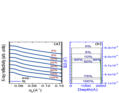
XRR patterns of Co-N thin films deposited for various are shown in fig. 1(a), they were fitted using Parratt’s formulism. Braun (7 99) Though total thickness oscillations could not be seen in XRR pattern due to large thickness, still a vital information about the film density is obtained, which decreases gradually as is increased. Obtained values of scattering length densities are plotted in fig. 1 (b). Roughness of film surface was typically about 1.3-1.5 nm.
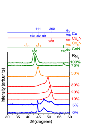
XRD pattern of samples deposited for different are shown in fig. 2. For =0, pure Co phase is observed however a faint peak at 2=51.4 degree corresponding to (200) reflection can also be seen. Co is known to stabilize in phase below 690 K and above it, in phase. Zhang et al. (1999); Yoo et al. (2000) However, co-existence of both phases in thin films is also seen.Ko et al. (2003); Vaz, Bland, and Lauhoff (2008) For the sample prepared at =5, the structure remains similar to 0 sample, but peak widths become broader due to interstitial incorporation of N atoms. Gupta and Gupta (2005) As increases to 10, the structure changes and reflection corresponding to (200) can be seen. A rather broad tail on the onset of this peak, is due to (111) (discussed later). An increase in for 20 and 30, leads to shift in this peak towards lower angles indicating an expansion in of (see table 1). For = 50, the phase identified is Co3N and for =75, the structure changes again to cobalt mononitride(CoN). For =100, CoN(200) peak gets broadened due to nanocrystallization. Gupta and Gupta (2005) To correlate N at.% with the structure of samples, secondary ion mass spectroscopy measurements were performed. Using a procedure adopted for Fe-N thin films,Gupta et al. (2011a, b) we find N at.% for =30 and 100% samples is 203 and 504, respectively, which is expected for and CoN structures. Grain sizes and obtained from the most intense peak in XRD pattern are given in table 1.
| crystal | grain | magnetic | ||
|---|---|---|---|---|
| () | structure | size(nm) | (nm) | moment() |
| (0.05) | (1) | () | (0.05) | |
| 0 | 33 | 0.407 | 1.7 | |
| 5 | 22 | 0.406 | 1.6 | |
| 10 | 6 | 0.358 | 1.6 | |
| 20 | 9 | 0.362 | 1.75 | |
| 30 | 7 | 0.370 | 1.85 | |
| 50 | 7 | 0.431 | 1.5 | |
| 75 | 19 | 0.418 | 0 | |
| 100 | 10 | 0.423 | 0 |
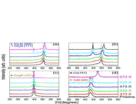
To resolve the structure and to study the thermal stability, annealing of selected samples deposited for =20, 30, 50 and 100% was carried out. Samples were annealed in a vacuum furnace (pressure 110-6 mabr) for about 1 hour and XRD measurements were carried out after each annealing as shown in figure 3(a)-(d), for =20,30,50 and 100%, respectively. For =20 and 30%, XRD pattern are identical to pristine state up to 423 K. Above it, there are notable changes: (i) the peak corresponding to (200) reflection of shifts towards higher angles (ii) a new peak corresponding to (111) starts to emerge. The peak shift upon annealing is more for =30% sample and the intensity of (111) reflection is also more prominent in this case. The peak shift towards higher angle is a clear signature of contraction in . The value of remains constant at 0.370 nm up to 423 K and at 573 K it becomes 0.356 nm for =30 sample. On the other hand, the sample deposited at =50%, show very little changes with annealing temperature, only peak width decreases, signifying grain growth with annealing. For =100% sample, we find that the structure is stable only up to 423 K and at 473 K, the broad peak observed for the pristine sample, splits into two peaks, one corresponding to CoN(200) and other to (111). Further annealing at 573 K results in formation of pure Co phase.
The XRD measurements carried out in the pristine and annealed samples provide an insight about the phase formation the thermal stability of samples. Broadly, observed behavior is in line with those reported by Fang et al. Fang et al. (2004) and Oda et al. Oda, Yoshio, and Oda (1987) Interestingly, an incremental increase in the of for =20 and 30%, immediately opens up a possibility to testify the large-volume high-moment approach for . Under this model the relation between the and average magnetic moment () is given by Imai, Takahashi, and Kumagai (2010)
| (1) |
where is the atomic fraction, , and are parameters. For precise measurement of , polarized neutron reflectivity (PNR) is a well-known technique. Unlike bulk magnetization techniques, it is independent of substrate magnetization and sample mass. Blundell and Bland (1992) It is surprising to note that PNR has not yet been used for quantification of in Co-N thin films. Neutrons being spin particles have two states of quantization, parallel (+) or antiparallel (-) to applied external field (). Neutrons interact with the magnetic field generated by unpaired spins on an atomic magnet via dipolar interaction. The magnetic potential for such kind of interaction is given by Hope et al. (1997) . Where magnetic induction , is neutron magnetic moment and M is sample magnetization. We did PNR measurements at Narziss neutron reflectometer at SINQ/PSI, Switzerland. During measurements a magnetic field of about 0.2 Tesla was applied (parallel to sample surface) to saturate them magnetically. Measured PNR for spin-up () and spin-down () can be directly used for the two spin states of neutron using spin asymmetry (), given by: Blundell and Bland (1992) . PNR pattern and for samples prepared using different are shown in fig. 4 (a) and (b), respectively.
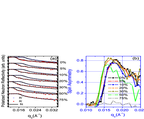
Since is a directly proportional to , it can be compared to see the relative changes as increases. Compared to =0% sample, decreases marginally for =5 and 10 samples. However for =20 and 30 samples, takes an upturn and its maximum shifts towards lower . While the shift to lower is due to overall reduction in film density, an increase in the maximum value of , is a direct measure of enhanced as compared to pure Co films. When is increased to 50, the maxima in the drops-off rapidly and for =75, and , indicating that the sample has become non-ferromagnetic. For =100, results (not shown) are similar to =75 case.
To get qualitative information of , PNR pattern were fitted using SimulReflec software Ott (2011) and density of films obtained from XRR measurements was taken as a input. Obtained values of are given table 1. It can be seen as is increases, first decreases and and than it increases for =20 and 30 samples. For =50%, it decreases again and finally becomes zero for samples prepared at =75 and 100%. From eq.1, it is expected as increases, should increase. Although such enhancement is theoretically predicted Imai, Sohma, and Suemasu (2014); Matar, Houari, and Belkhir (2007); Houari, Matar, and Belkhir (2010), it is evidenced experimentally in this work for thin films.
It may be noted that the experimentally obtained values of for are typically 0.357 nm Oda, Yoshio, and Oda (1987); Lourenço et al. (2014); Ito et al. (2011c), much smaller than the theoretically predicted value at 0.373 nm Matar, Houari, and Belkhir (2007). While for pure Co (), =0.354. We find that for =0.358 nm(=10 sample), the value of is lower than that of pure Co, as observed in other studies. However, for =30, =0.370 nm and in this condition, it is expected that of Co in should be larger than that of pure Co. Here it is interesting to note that in most of the studies, films have always been deposited at elevated temperature between 433-723 K. Theoretical calculation predict that the heat of formation () for Co-N system are even larger than than that of Fe-N system Häglund et al. (1993)). In this situation, when deposited at elevated temperature, nitrogen deficient films are obtained characterized by smaller than theoretical values of . When deposited at room temperature, nitrogen incorporation within can be maximized leading to enhanced the magnetic moment as observed in our samples.
In conclusion we studied the phase formation, thermal stability and magnetization of Co-N thin films prepared using dcMS at room temperature. We find that Co,,Co3N and CoN phases are formed as increases. While and CoN phases are stable only up to about 423 K, Co3N phase is more stable. More remarkable results are obtained for films. As phase is formed, an incremental increase in results in an expansion of lattice constant, which in turn results in an enhanced Co magnetic moment in phase.
One of author (RG) would like thank UGC-DAE CSR, Indore for a CRS project and to Ajay Gupta and V. Ganesan for support and encouragements. A part of this work was performed at Narziss, SINQ/PSI, Villigen, Switzerland. We are thankful to C. Schanzer and M. Schneider for providing access to Narziss, M. Horisberger for sputtering, V. R. Reddy and A. Gome for XRR and L. Behera for help in XRD and SIMS measurements. We acknowledge DST, New Delhi for providing financial support to carry out NR experiments.
References
- Ji et al. (2011) N. Ji, L. F. Allard, E. Lara-Curzio, and J.-P. Wang, Applied Physics Letters 98, 092506 (2011).
- Ito et al. (2011a) K. Ito, G. H. Lee, K. Harada, M. Suzuno, T. Suemasu, Y. Takeda, Y. Saitoh, M. Ye, A. Kimura, and H. Akinaga, Applied Physics Letters 98, 102507 (2011a).
- Atiq et al. (2008) S. Atiq, H.-S. Ko, S. A. Siddiqi, and S.-C. Shin, Applied Physics Letters 92, 222507 (2008).
- Bhattacharyya (2015) S. Bhattacharyya, The Journal of Physical Chemistry C 119, 1601 (2015).
- Tayal et al. (2014) A. Tayal, M. Gupta, N. P. Lalla, A. Gupta, M. Horisberger, J. Stahn, K. Schlage, and H.-C. Wille, Phys. Rev. B 90, 144412 (2014).
- Imai, Sohma, and Suemasu (2014) Y. Imai, M. Sohma, and T. Suemasu, Journal of Alloys and Compounds 611, 440 (2014).
- Matar, Houari, and Belkhir (2007) S. F. Matar, A. Houari, and M. A. Belkhir, Phys. Rev. B 75, 245109 (2007).
- Matsuoka, Ono, and Inukai (1986) M. Matsuoka, K. Ono, and T. Inukai, Applied Physics Letters 49 (1986).
- Oda, Yoshio, and Oda (1987) K. Oda, T. Yoshio, and K. Oda, Journal of Materials Science 22, 2729 (1987).
- Suzuki et al. (1995) K. Suzuki, T. Kaneko, H. Yoshida, H. Morita, and H. Fujimori, Journal of Alloys and Compounds 224, 232 (1995).
- Asahara et al. (2001) H. Asahara, T. Migita, T. Tanaka, and K. Kawabata, Vacuum 62, 293 (2001).
- Fang et al. (2004) J.-S. Fang, L.-C. Yang, C.-S. Hsu, G.-S. Chen, Y.-W. Lin, and G.-S. Chen, Journal of Vacuum Science & Technology A 22 (2004).
- Jia et al. (2008) H. Jia, X. Wang, W. Zheng, Y. Chen, and S. Feng, Materials Science and Engineering: B 150, 121 (2008).
- Paduani (2008) C. Paduani, Solid State Communications 148, 297 (2008).
- Houari, Matar, and Belkhir (2010) A. Houari, S. F. Matar, and M. A. Belkhir, Journal of Magnetism and Magnetic Materials 322, 658 (2010).
- Imai, Takahashi, and Kumagai (2010) Y. Imai, Y. Takahashi, and T. Kumagai, Journal of Magnetism and Magnetic Materials 322, 2665 (2010).
- Takahashi, Imai, and Kumagai (2011) Y. Takahashi, Y. Imai, and T. Kumagai, Journal of Magnetism and Magnetic Materials 323, 2941 (2011).
- Ito et al. (2011b) K. Ito, K. Harada, K. Toko, M. Ye, A. Kimura, Y. Takeda, Y. Saitoh, H. Akinaga, and T. Suemasu, Applied Physics Letters 99, 252501 (2011b).
- Ito et al. (2011c) K. Ito, K. Harada, K. Toko, H. Akinaga, and T. Suemasu, Journal of Crystal Growth 336, 40 (2011c).
- Bhandari et al. (2012) H. B. Bhandari, J. Yang, H. Kim, Y. Lin, R. G. Gordon, Q. M. Wang, J.-S. M. Lehn, H. Li, and D. Shenai, ECS Journal of Solid State Science and Technology 1, N79 (2012).
- Lourenço et al. (2014) M. Lourenço, M. Carvalho, P. Fonseca, T. Gasche, G. Evans, M. Godinho, and M. Cruz, Journal of Alloys and Compounds 612, 176 (2014).
- Liu et al. (2014) X. Liu, H. Lu, M. He, K. Jin, G. Yang, H. Ni, and K. Zhao, Journal of Alloys and Compounds 582, 75 (2014).
- Silva et al. (2014) C. Silva, A. Vovk, R. da Silva, P. Strichovanec, P. Algarabel, A. Gonçalves, R. Borges, M. Godinho, and M. Cruz, Thin Solid Films 556, 125 (2014).
- Silva et al. (2015) C. Silva, A. Vovk, R. da Silva, P. Strichonavec, P. Algarabel, A. Casaca, C. Meneghini, I. Carlomagno, M. Godinho, and M. Cruz, Journal of Alloys and Compounds 633, 470 (2015).
- Braun (7 99) C. Braun, Parratt32- The Reflectivity Tool (HMI Berlin, 1997-99).
- Zhang et al. (1999) H. Zhang, J. Poole, R. Eller, and M. Keefe, Journal of Vacuum Science & Technology A 17 (1999).
- Yoo et al. (2000) C. S. Yoo, H. Cynn, P. Söderlind, and V. Iota, Phys. Rev. Lett. 84, 4132 (2000).
- Ko et al. (2003) Y. Ko, D. Park, B. Seo, H. Yang, H. Shin, J. Kim, J. Lee, W. Lee, P. Reucroft, and J. Lee, Materials Chemistry and Physics 80, 560 (2003).
- Vaz, Bland, and Lauhoff (2008) C. A. F. Vaz, J. A. C. Bland, and G. Lauhoff, Reports on Progress in Physics 71, 056501 (2008).
- Gupta and Gupta (2005) R. Gupta and M. Gupta, Phys. Rev. B 72, 024202 (2005).
- Gupta et al. (2011a) M. Gupta, A. Tayal, A. Gupta, V. Reddy, M. Horisberger, and J. Stahn, J. Alloys and Compounds 509, 8283 (2011a).
- Gupta et al. (2011b) M. Gupta, A. Tayal, A. Gupta, R. Gupta, J. Stahn, M. Horisberger, and A. Wildes, J. Appl. Phys. 110, 123518 (2011b).
- Blundell and Bland (1992) S. J. Blundell and J. A. C. Bland, Phys. Rev. B 46, 3391 (1992).
- Hope et al. (1997) S. Hope, J. Lee, P. Rosenbusch, G. Lauhoff, J. A. C. Bland, A. Ercole, D. Bucknall, J. Penfold, H. J. Lauter, V. Lauter, and R. Cubitt, Phys. Rev. B 55, 11422 (1997).
- Ott (2011) F. Ott, SIMULREFLEC (V1.7 2011).
- Häglund et al. (1993) J. Häglund, A. Fernández Guillermet, G. Grimvall, and M. Körling, Phys. Rev. B 48, 11685 (1993).