Superconducting spin valve effect and triplet superconductivity in CoOx/Fe1/Cu/Fe2/Cu/Pb multilayer
Abstract
We report magnetic and superconducting properties of the modified spin valve system CoOx/Fe1/Cu/Fe2/Cu/Pb. Introduction of a Cu interlayer between Fe2 and Pb layers prevents material interdiffusion process, increases the Fe2/Pb interface transparency, stabilizes and enhances properties of the system. This allowed us to perform a comprehensive study of such heterostructures and to present theoretical description of the superconducting spin valve effect and of the manifestation of the long-range triplet component of the superconducting condensate.
pacs:
74.45+c, 74.25.Nf, 74.78.FkI INTRODUCTION
The antagonism of superconductivity (S) and ferromagnetism (F) arises from the fact that ferromagnetism requires parallel (P) and superconductivity requires antiparallel (AP) orientation of spins. The exchange splitting of the conduction band in strong ferromagnets which tends to align electron spins parallel is larger by orders of magnitude than the coupling energy for the AP alignment of the electron spins in the Cooper pairs in conventional superconductors. Therefore the singlet pairs with AP spins of electrons are easily destroyed by the exchange field in a homogeneous sample.
Just bearing in mind this strong antagonism, the spin valve effect in the F1/F2/S multilayer structure, where F1 and F2 are the F layers with uncoupled magnetizations, and S is the superconducting layer, has been theoretically predicted Oh . Preliminary analysis showed that at P orientation of magnetizations of F1 and F2 layers the superconducting transition temperature is lower than that in the case of their AP orientation, .
Recently we have experimentally demonstrated a full switching between the normal and superconducting state in an S/F thin film heterostructure Leksin1 . For that we have adapted the design by Oh et al. Oh and have optimized the materials choice and the specific geometry of the F1/F2/S scheme. For this layer sequence, we have chosen the following set of materials: cobalt oxide for the insulating antiferromagnetic bias layer which pins the magnetization of the F1 layer; Fe for the ferromagnetic F1 and F2 layers; Cu as a normal (N) metal layer between the F1 and F2 layers to decouple their magnetizations, and finally In for the S layer.
Our further important result was the observation of the sign-changing behavior of the spin valve effect by varying the F2-layer thickness Leksin2 ; Leksin3 . To understand this observation, we have analyzed our results in the framework of the theory by Fominov et al. Fominov2 which predicts an oscillating behavior of due to the interference effects for the superconducting pairing function reflected from both surfaces of the F2 layer.
This theoretical paper generalizes the theory of the spin valve effect for F1/F2/S structure taking into account the appearance of the long-range triplet component (LRTC) in the superconducting condensate predicted by Bergeret et al. Bergeret1 . According to Ref. Fominov2 the appearance of the triplet component in the reference F1/F2/S spin valve system should manifest itself as a minimum in the in-plane angular dependence of at a noncollinear orientation of magnetizations of the F1 and F2 layers. Unfortunately, such experiment for the CoOx/Fe1/Cu/Fe2/In system turned out to be unrealizable under the well-controlled conditions owing to a low value of for indium and its extreme sensitivity to small out-of-plane tilting of the external magnetic field. In this respect lead has much better superconducting critical parameters which have determined its choice as an S layer in our previous study Leksin4 . Indeed, in the multilayer spin-valve heterostructure CoOx/Fe1/Cu/Fe2/Pb we have observed indications of the LRTC in the superconducting condensate arising due to the penetration of the Cooper pairs into two F layers with noncollinear orientation of magnetizations. The LRTC manifested in a nonmonotonic behavior of the superconducting transition temperature of the Pb layer upon gradual rotation of the magnetization of the ferromagnetic F2 layer with respect to the magnetization of the F1 layer from the P to the AP orientation. We observed a clear minimum of for a noncollinear configuration of and . As follows from our analysis in the framework of the theory of the superconducting triplet spin valve Fominov2 , such minimum of is a fingerprint of the LRTC generated by noncollinear magnetizations and .
Though we could achieve qualitative understanding of the experimental signatures of the LRTC, a rapid degradation of our heterostructures and a nonperfect properties of the F2/S interface prevented to obtain a comprehensive picture of the generation and experimental manifestation of the triplet component in the superconducting condensate in the S/F spin valve.
The major goal of the present work was twofold: (i) to improve the stability and the performance of the S/F heterostructures; (ii) to investigate the physical properties of the modified structures and to provide a theoretical description of the ordinary spin valve and the LRTC effects.
The paper is organized as follows. For the sake of completeness we briefly review the spin valve effect and the generation of LRTC in spin valve structures in Section II. The preparation technique and optimization of the properties of the films is described in Section III. In Section IV we present magnetic and normal state transport properties. Section V contains the main experimental data on the superconducting and spin valve properties of the samples. In Section VI we perform theoretical analysis of the obtained results. Finally, the work is summarized in Section VII.
II State of art
II.1 Superconductor/ferromagnet proximity effect
In a metallic ferromagnet there exists the -exchange interaction between spins of localized moments () and spins of conduction electrons () in the form of . If localized moments with concentration are aligned ferromagnetically (in parallel), then the spatially averaged Hamiltonian becomes . This ferromagnetic interaction means that conduction electrons with spin-up and spin-down orientations have different energies. Thus, the conduction band in the F layer turns out to be split into two subbands. The splitting (the difference of energies for spin up and spin down) is then . For 3d-transition metal ferromagnets (such as Mn, Fe, or Co) this splitting is of the order of 1 eV. One can imagine that this is a result of the Zeeman splitting under the influence of the so-called exchange field . In terms of the exchange energy, the splitting is .
In turn, the coupling energy for the electrons in the Cooper pairs according to the Bardeen-Cooper-Schrieffer (BCS) microscopic theory of superconductivity amounts to BCS (here is the Boltzmann constant and is the superconducting transition temperature). It is three orders of magnitude smaller than the splitting of the conduction band of a 3d ferromagnet. That is why 3d ferromagnetism strongly suppresses conventional singlet superconductivity. For this reason in thin film superconductor/ferromagnet heterostructures the Cooper pairs can penetrate into an F layer over a small distance only. Considering the superconducting layer in the “dirty” limit, i.e. in the regime when the mean free path of conduction electrons in a superconductor is much smaller compared to the BCS coherence length , the characteristic depth of the decay of the pairing function in the F layer is given by the diffusion coefficient and the exchange energy of the F layer Radovic . For iron film the value of is less than 0.8 nm (see, e.g., Lazar ).
II.2 Superconducting spin valve
The physical origin of the spin valve effect based on the S/F proximity effect relies on the idea to control the pair-breaking, and hence the superconducting transition temperature , by manipulating the mutual orientation of the magnetizations of the F layers in a heterostructure comprising, e.g., two F and one S layer in a certain combination. The first spin valve structure based on the S/F proximity effect has been proposed by Oh et al. Oh . According to this theory the superconducting spin valve effect in F1/F2/S structures takes place because the mean exchange field from two F layers acting on Cooper pairs in the S layer is smaller for the AP orientation of the magnetizations of these F layers compared to the P case. However, it has been shown recently Fominov1 ; Fominov2 that the situation is not that simple. It is well known (see, e.g., the review buzdin ) that in a ferromagnetic layer the Cooper pair acquires a nonzero momentum due to the Zeeman splitting of the electron levels and thus its wave function oscillates in space. If the F layer is sufficiently thin, the wave function reflected from the surface of the F layer opposite to the S/F interface can interfere with the incoming one. Depending on the F layer’s thickness, the interference at the S/F interface may be constructive or destructive. This should apparently lead to an enhancement of of S/F structure (direct spin valve effect with in a spin valve structure) or to its decrease (inverse spin valve effect, ), respectively. Another structure proposed also theoretically Tagirov ; Buzdin ; Buzdin1 is the scheme F1/S/F2 with the operation principle similar to that described above. For both structures the interference effects can lead to nontrivial behavior of . At the same time, the difference in operation of these two structures consist in that for F1/F2/S structure the direct and inverse spin valve effects can be realized and for F1/S/F2 structure only the direct effect is expected.
A large number of works confirmed the predicted influence of the mutual orientation of the magnetizations in the F1/S/F2 structure on (see, e.g., Gu ; You ; Potenza ; Pena ; Moraru ; Miao ). However, the magnitude of the spin valve effect turns out to be smaller than the width of the superconducting transition itself. Hence a full switching between the normal and the superconducting state was not achieved. Structures similar to suggested by Oh et al. Oh were investigated to a less extent. A studied [Fe/V]n antiferromagnetically coupled superlattice with thick superconducting vanadium layer on the top instead of a single F1/N/F2 trilayer Westerholt ; Nowak ; Nowak1 was not actually the spin valve device because the system could not be switched from the AP to P orientation of the magnetizations instantaneously. At the same time the analysis of the temperature dependence of the critical field has shown that implicitly of this structure can reach up to 200 mK at 100 mK.
Comparison of the experimental results obtained for both proposed structures of the spin switches gives grounds to conclude that the scheme proposed by Oh et al. Oh may be the most promising for the realization of the full spin switch effect for the superconducting current in an S/F thin film heterostructure. Later on a set of asymmetric structures was theoretically proposed proshin ; avdeev ; avdeev1 which are not yet experimentally tested.
II.3 Long-range triplet superconductivity
Bergeret et al. Bergeret1 underlined the fact that the odd-frequency triplet superconductivity arises in S/F systems with conventional s-wave singlet BCS-type superconductors; they further demonstrated that in the case of inhomogeneous magnetization of the F part, some of the odd-frequency superconducting components become long-range. The diffusive Josephson junctions with the F layers and noncollinear orientation where long-range Josephson coupling may exist, have been analyzed in Refs. bergeret2 ; houzet ; eschrig . Volkov et al. bergeret2 considered F′SFSF′ structure with different magnetization orientations in the F and F′ layers. It was shown that in the F′ layer the triplet component arises with the total spin of the Cooper pair . This component is insensitive to the exchange field and can penetrate into the F layer over a distance much larger than . This is the reason why the superconducting odd component has been named long-range triplet component. The LRTC can also be generated in the system with spatial or momentum dependence of the exchange field, as well Melnikov ; Booniad .
In order to comprehend this fact, let us assume that the magnetization of the F2 layer in the F1/F2/S system is directed along the -axis. When the singlet Cooper pairs enter this ferromagnetic layer, the triplet component with zero spin projection on the axis is generated. Then these Cooper pairs penetrate into the F1 layer where the magnetization is directed along axis. Now the triplet component with zero projection on the axis has projections on the axis, which corresponds to the equal-spin pairing which is just the LRTC. The series of experiments were performed (see, e.g., reviews bergeret ; buzdin ; efetov ; efetov2 ) which show an anomalously deep penetration of the superconducting condensate into the F layer typical for the triplet superconductivity.
Finally, we mention that earlier indications for long-range superconductivity in an F layer have been detected through the proximity-induced conductance giroud ; petrashov even before the theoretical works have appeared. Recently the occurrence of the odd in the Matsubara frequency triplet superconductivity in the S/F systems, predicted in Ref. bergeret2 was inferred from the experiments on the differential conductance visani and on Josephson junctions through observation of an anomalously deep penetration of the Cooper condensate into the F layer (see, e.g., sosnin ; keizer ; chan ; blamire ; aarts1 ; khire ; Westerholt1 ).
We note that our experiments Leksin4 were advantageous in that they address the primary superconducting parameter of the spin valve, the behavior of , which is directly affected by the spin-triplet component. Recently for the structure of the spin valve similar to the studied by us an evidence for generation of LRTC was obtained as well zdravkov ; Wang .
III Samples
In our previous study of the spin valve construction CoOx/Fe1/Cu/Fe2/Pb Leksin4 the sample degradation on a time scale of a week was observed. This prevented a long-term detailed study of the properties of the samples. We suppose that this degradation was caused by the interdiffusion of Fe and Pb atoms through the Fe2/Pb interface. To prevent such an interdiffusion an introduction of the antidiffusion (AD) interlayer between Fe2 and Pb layers may be helpful. For that purpose we have chosen a copper film Leksin5 .
III.1 Design
The final design of the samples is depicted in Fig. 1. The
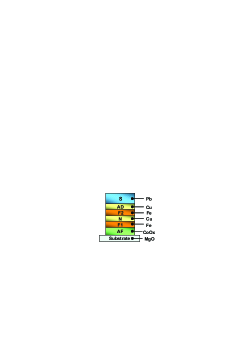
CoOx/Fe1 is a standard combination providing a high pinning effect of the Fe1 layer magnetization. The antiferromagnetic CoOx layer has the Néel temperature K, depending on the oxygen content . After the in-plane magnetic field cooling procedure from 300 K down to 4 K the magnetization of the Fe layer contacting the CoOx layer is strongly pinned in the direction of the field. However, the Fe2 layer’s magnetization is not pinned since it is decoupled from Fe1 magnetization by a nonmagnetic 4 nm thick Cu layer. Thus the mutual orientation of the Fe1 and Fe2 layer’s magnetizations can be changed using a small external magnetic field applied in the desired direction. A thin Cu layer separates the Fe2 and S layer. As it will be shown below (see, e.g., Fig. 3) this conducting Cu interlayer does not influence and the proximity effect between Fe2 and Pb layers. Since the top Pb layer is air-sensitive all samples were capped by a 85 nm thick isolating Si3N4 layer. It does not cause an additional proximity effect with the S layers since it is not conducting.
III.2 Preparation
Metallic layers were grown on high-quality MgO (100) substrates using classical e-gun technology in ultra-high vacuum (UHV) conditions of about mbar within a closed vacuum cycle. The evaporation chamber has a load-lock station allowing to avoid vacuum breaking before substrate load. Substrate temperature was kept at 300 K to avoid undesired alloying between the neighboring layers. The thickness of the films during the growth was controlled by a standard quartz-crystal monitor system. All materials used for evaporation had a purity of better than 4N, i.e. the contamination level could be kept below 0.01 at %. The substrates were fixed at a small rotating wheel on the sample holder. After that the sample holder was placed inside the load-lock station. The rotating wheel system allows to prepare a set of samples with varied parameters at the same evacuation cycle. The Co oxide layer was prepared in two stages. First, the metallic Co film was deposited on the substrates. On the second stage it was transferred to the load-lock station were the Co film was oxidized using 2 hours exposure at 100 mbar of pure oxygen gas. After the oxidation procedure the samples were returned to the UHV deposition chamber where the layers growth process was continued. On the final stage the samples were transferred to the neighboring sputtering chamber were they were capped by a 85 nm thick Si3N4 insulating protection layer. In order to prepare high quality samples the deposition rates for the materials were optimized. For Co, Fe, Cu we used the rates of 0.05 nm/s and for Pb — 4 nm/s.
III.3 Fe/Pb interface quality
Our first studies of the proximity effect in the Fe/Pb samples revealed that the time stability of the interface between Fe and Pb materials was rather limited Leksin5 . Hence the sample properties were stable within one week period only. Fig. 2 shows the time evolution of the superconducting properties of the Fe/Pb systems. In the
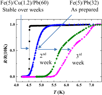
structures without the AD layer the superconducting transition width rises up to 1.5 K and the shifts to its bulk value of 7.2 K during the first few weeks. A light annealing at 100∘ C of the freshly prepared samples leads to their instant degradation. Such behavior of the superconducting transition curve can be caused by the weakening of the suppression through the Fe/Pb interface. As mentioned above the most probable reason for that is the interdiffusion of Fe and Pb atoms through the Fe2/Pb interface. Indeed, the introduction of a thin 1.2 nm Cu interlayer stabilizes the interface and inhibits the broadening with time of the superconducting transition and of the shift (Fig. 2). Importantly, we find that the Cu interlayer is almost transparent for the Cooper pairs penetrating from S to F layer. The penetration depth of the Cooper pairs into a nonmagnetic metal is usually associated with the Cooper pairs coherence length inside the N layer. In our measurements of of the Cu/Pb bilayer at small Cu-layer thicknesses, the decreases monotonically when -layer thickness increases (Fig. 3).
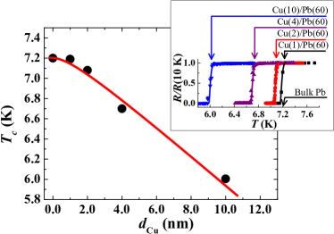
This result shows that the penetration depth of the Cooper pairs exceeds the Cu antidiffusion layer thickness at least by 10 times. Thus one can conclude that nm is an optimal thickness of the AD layer to stabilize the Fe/Pb interface without affecting .
IV Magnetic and superconducting characterization
IV.1 Magnetic measurements
All samples were magnetically characterized using a standard 7T VSM SQUID magnetometer (Fig. 4).
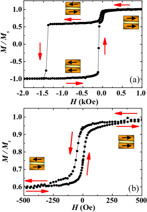
First, the sample was cooled down from 300 K to 10 K in the presence of the in-plane magnetic field kOe. At 10 K the magnetic field was varied from kOe down to kOe and back again. During this variation the in-plane magnetic moment of the sample was measured. It turns out that for most of the samples CoOx/Fe1/Cu/Fe2/Cu/Pb the magnetic field of about Oe is enough to get fully saturated magnetization of the free Fe2 layer while the magnetization of the Fe1 layer remains fixed up to the operating field of the order of kOe. This upper limit strongly depends on the Fe1-layer thickness. If the operating field is larger than this upper limit, then both magnetizations start to rotate and the angle between them is not clearly defined in the experiment. The hysteresis magnetization loop for each Fe layer has its own saturation value, proportional to the thickness of the Fe layer. The SQUID data were also used to correct the Fe-layers thickness using the specific magnetic saturation value which was of the order of the bulk value of 1730 emu/cm3.
IV.2 Electrical resistivity
The electrical resistivity measurements were performed using the standard four-point method. The top insulating layer was mechanically removed at the points where the golden wires should be attached to the surface of the sample.
The is defined as the midpoint of the superconducting transition. The experimental setup for the transport measurements is a combination of an electrical setup with a vector electromagnet that enables a continuous in-plane rotation of the sample in magnetic field. For a precise control of the magnetic field value a Hall probe with a sensitivity better than Oe was used. To avoid the occurrence of the unwanted out-of-plane component of the external field the sample plane position was always adjusted with an accuracy better than relative to the direction of the dc external field.
The quality of the Pb layers can be judged from the residual resistivity ratio , where is the measured resistance at temperature , (300 K) is the phonon contribution to the specific resistivity at 300 K and (4 K) is the residual resistivity at 4 K. For the studied samples is about 15. The high value of is usually correlated with a high purity of the films. Since the room temperature resistivity of the Pb layer is dominated by the phonon contribution cm (see, e.g., Kittel ) one can estimate the residual specific resistivity from the value. We obtain (4K)=1.47 cm. The Pippard relations Pippard
| (1) |
give
| (2) |
Here is the Fermi surface area, and are the mean free path and Fermi velocity of conduction electrons, both averaged over the Fermi surface, and is the electronic specific heat coefficient. Using for Pb erg/K2cm3 (Ref. Kittel, ), we obtain cm2/s and the corresponding diffusion constant in the S layer cm2/s. In our case cm/s Kittel . This means that the mean free path of conduction electrons in Pb is nm. The BCS coherence length for Pb amounts to nm Deutscher1 . The comparison of the mean free path of conduction electrons with the superconducting coherence length shows that implying the dirty limit for the superconducting part of the system. The S-layer coherence length for the dirty limit reads
| (3) |
where is the critical temperature of the S layer. We follow notations of Ref. Fominov3 restoring and in Eqs. (3)-(4) since the are used in other formulas in the paper. Equation (3) gives nm for our samples.
We also tried to measure the residual resistivity of the Fe layers in the thickness range corresponding to the studied spin valve samples. We cannot measure the partial resistivity of each layer in the multilayer sample. Therefore, we had to measure the resistivity of such thin layers using single layer and bilayer films. It turns out that iron films grown directly on the MgO substrate at room temperature become discontinuous at a thickness below 10 nm. Therefore we prepared the set of samples MgO/Cu(4 nm)/Fe(). In this case the quality of the iron layer was much better, and for Cu(4 nm)/Fe(5 nm) we found that of the order of 10-30 cm. Such a big scatter of the resistivity values is caused by different roughnesses of the iron layers. Possibly, residual resistivity of the Fe2 layer in a real multilayer could be different. For our analysis we shall use an “optimistic” value of the residual resistivity for iron cm. Using Eq. (2) we obtain cm2/s, cm2/s and nm. In notation of Ref. Fominov3 , we have
| (4) |
From this equation we get nm.
V Experimental results
V.1 Dependence of the superconducting transition temperature on Pb- and Fe-layers thickness
On the first stage of experiments the magnetic part of the system CoOx/Fe1/Cu/Fe2 was optimized in order to get a well-defined control of the mutual orientation of the Fe1 and Fe2 layers’ magnetizations. For such combination we found the optimal thicknesses for the CoOx layer of 2.5 nm and for the Cu interlayer of 4 nm. The pinning effect for the combination CoOx/Fe1 is not strongly affected by the CoOx thickness variation. However artefacts in the results of magnetic measurements may result from the incomplete magnetization pinning when the thickness of the Co layer is not large enough to form a uniform CoOx film on the MgO substrate. The Cu interlayer thickness of 4 nm was found to be optimal to prevent magnetic coupling between Fe1 and Fe2 layers at low temperatures.
The aim of the second step was the finding of the optimal Pb-layer thickness for the observation of the S/F proximity effect. The Pb-layer thickness should be sufficiently small to make the whole S layer sensitive to the magnetic part of the system. Only in this case the mutual orientation of the Fe-layers’ magnetizations would affect of the system. In order to define the optimal thickness we measured the dependence on the Pb layer thickness for the Fe/Pb and Fe/Cu/Pb systems (Fig. 5).
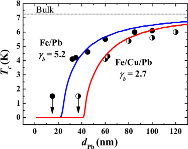
The value for the Fe/Cu/Pb starts to decrease rapidly when the thickness of the Pb layer is reduced down to 80 nm. At 40 nm the is less than 1.5 K. According to Fig. 5 the optimal thickness of the Pb layer lies between 80 and 40 nm. At small the width of the superconducting transition curves gets extremely large, of the order of 0.5 K. Most likely it is caused by the roughness of the Pb layer which become important at small where the derivative is large. For the samples with nm, we obtain K with a quite small of 50 mK. The for these samples is low enough in comparison with the bulk Pb. Note that, first, the -suppression by the 5 nm thick iron layer for nm is about 3 K and, second, the thickness nm only slightly exceeds the superconducting coherence length nm. This suggests the thickness nm as the optimal thickness for our study. According to Fig. 5 for the Fe(5 nm)/Pb(60 nm) system without Cu antidiffusion layer the is higher than for Fe(5nm)/Cu(1.2 nm)/Pb(60 nm). For nm the difference reaches 1 K. This cannot be explained by an additional shift due to the contact Cu/Pb, since the difference between Cu(1.2 nm)/Pb(60 nm) and Pb(60 nm) is less than 0.1 K (see Fig. 3). This shift is caused most probably by a lower interface quality in the case of Fe/Pb as compared to Fe/Cu/Pb.
The next logical step was to check whether the superconductivity is influenced by both ferromagnetic layers. One of the simple ways to check this is to study separately the influence of each component of the layer sequence in the sample CoOx(2.5)/Fe1(4)/Cu(4)/Fe(0.5)/Cu(1.2)/Pb(60) by a stepwise replacing of the ferromagnetic Fe layers by a non-magnetic Cu layer with the same thickness (Fig. 6).
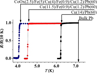
The pair-breaking effect for the Fe layer is different than that for Cu. This would result in a change of . As expected, the lowest K was observed for the full stack of magnetic layers CoOx(2.5)/Fe1(5)/Cu(4)/Fe(0.9)/Cu(1.2)/Pb(60). When the magnetic part CoOx(2.5)/Fe1(5)/Cu(4) was replaced by the nonmagnetic Cu(11.5) layer with the same total thickness, the value increased up to 4.5 K. And finally, the substitution of the whole magnetic part CoOx(2.5)/Fe1(5)/Cu(4)/Fe(0.9)/Cu(1.2) by Cu(14) resulted in a significant change of up to 6.25 K. These results evidence that the Cooper pairs penetrate from the superconducting Pb layer through the Fe2 layer inside the magnetic part and sense all layers including the Fe1 layer.
V.2 Superconducting spin valve effect
The magnitude of the superconducting spin valve effect is the measure of the difference between the critical temperatures for AP () and P () orientations of magnetizations of the F layers. After the field cooling procedure at kOe the Fe1 layer magnetization is pinned in the positive direction by antiferromagnetic CoOx even at high switching magnetic field up to kOe (Fig. 4(a)). Also the direction of the Fe2 layer magnetization is positive providing initial P state. The Fe2 layer magnetization is not pinned and the application of a small switching field in the negative direction can switch the mutual orientation from P to AP state (Fig. 4(b)). The saturation field for the Fe2 film is of the order of 500 Oe. This means that the switching field Oe is sufficient to sustain a homogenous magnetization for the Fe2 layer following the switching field direction without formation of the domain structure.
The superconducting spin valve effect was measured for two sets of samples CoOx(2.5)/Fe1(2.5)Cu(4)Fe()/Cu(1.2)/Pb(60) and CoOx(2.5)/Fe1(2.5)Cu(4)Fe()/Pb(60). The first set contains a Cu AD layer, the second one does not contain this layer. In both sets the Fe2 layer thickness is varied while other layers’ parameters are fixed. The thickness of the Fe1 layer nm is much larger than which is less than 0.8 nm. Hence the is not affected by the variation. The results for these two sets with varying at fixed nm are demonstrated in Fig. 7.
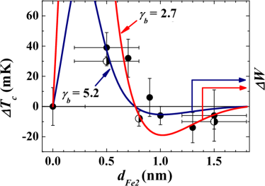
The -dependence exhibits a well-defined sign-changing oscillating behavior. First, at nm the has a maximum of +40 mK. The positive value implies the direct effect, . An increase of value causes a reduction of down to 0 mK around nm. Notably, when increases further above 1 nm, the falls down to a negative minimum of -15 mK at 1.3 nm and then rises up back to 0 at 1.5 nm. It is also important to note that the oscillating behavior for this dependence is a characteristic feature for both types of systems containing the Fe/Pb and Fe/Cu/Pb interfaces. Similar result was also observed in the case of CoOx/Fe/Cu/Fe/In heterostructures (Refs. Leksin2 ; Leksin3 ).
In order to investigate the dependence of the magnitude of the superconducting spin valve effect on the Fe1 layer thickness we also studied a set of samples CoOx(2.5)/Fe1()/Cu(4)/Fe()/Cu(1.2)/Pb(60) with two fixed Fe2-layer thicknesses 0.5 and 0.9 nm. The results for the samples with =0.5 nm are depicted in Fig. 8.
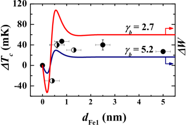
One can see that the dependence in Fig. 8 have the minor maximum of at the values of of the order of 0.8 nm. Qualitatively, the maximum in is due to the optimized value of . For relatively thin Fe layers of nearly equal thicknesses, the exchange fields in the antiparallel configuration effectively cancel each other, leading to a maximized . When increasing from 0.5 to 0.9 nm the magnitude of approaches zero in accordance with Fig. 7. With further increasing the spin valve effect change sign but still remains very small. Another interesting feature of these dependences is the negative minimum at extremely small Fe1 layer thickness (Fig. 8(a)). This kind of oscillations of is also due to the interference effects as it was in the case of the dependence (Ref. Leksin2 ). For our sample growth technique, the thinnest uniform Fe layers which can be prepared has, in the best case, a thickness of 0.5 nm and not less. However, for the CoOx/Fe1 part we observed a partial oxidation of the Fe layer. The oxidation depth of the Fe1 layer is about 0.4-0.6 nm. Thus, preparation of a sample stack CoOx/Fe1(1)/Cu/Fe2/Pb actually yields the stack with the effectively smaller thnickness of the Fe1 layer of 0.4 - 0.6 nm CoOx/Fe1(0.4-0.6)/Cu/Fe2/Pb. We also successfully used this effect to reduce the thickness of the Fe1 layer down to 0.3-0.4 nm (Fig. 8(a)).
The full switching of the supercurrent was achieved for the sample CoOx/Fe1(0.8)/Cu(4)/Fe2(0.5)/Cu(1.2)/Pb(60) which has the maximum according to Fig. 8(a). The difference in between AP and P states for this sample is clearly seen in Fig. 9.
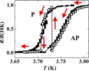
The superconducting transition temperature for the AP orientation of the magnetizations occurs at a temperature exceeding for the P orientation by 40 mK, which is of the order of the superconducting transition width . This opens a possibility to switch off and on the superconducting current flowing through our sample almost completely within the temperature range corresponding to the -shift by changing the mutual orientation of the magnetizations of Fe1 and Fe2 layers. To demonstrate this we have performed resistivity measurements of the sample by sweeping slowly the temperature within the and switching the magnetic field between and kOe. We note that the full switching of the supercurrent using the proximity effect was observed for the first time in the CoOx/Fe/Cu/Fe/In system Leksin1 . However, using Pb instead of In allowed us to improve the critical parameters of the system. In particular, we have increased the operating temperature from 1.4 K for Fe/In-based systems up to 3.7 K for Fe/Cu/Pb based systems which is near the 4He boiling point.
V.3 Triplet spin valve effect
The triplet spin valve effect in F1/F2/S systems manifests itself in a non-monotonic variation of the value upon a continuous change of the angle between magnetizations of the F1 and F2 layers from 0 to 180∘, with a minimum of corresponding to a noncollinear orientation Fominov2 . According to theory, the minimum is most pronounced if it takes place near the orthogonal orientation of the F-layers’ magnetization. This feature is a fingerprint of the LRTC arising in the system. This component is generated from the short-range triplet component at the F1/F2 interface. In its turn, the short-range triplet component with zero projection of spins is generated from the conventional singlet Cooper pairs penetrating from the S layer into the magnetic part of the structure. The result of this proximity effect is a decrease of due to “leakage” of Cooper pairs from the S layer. The “leakage channel” caused by the generation of LRTC at the F1/F2 interface should be sensitive to the number of Cooper pairs reaching the interface. Hence, the magnitude of the triplet spin valve effect is sensitive to the F2 layer thickness. The penetration depth of the short-range components inside the F2 layer is of the order of and in the case of Fe it is extremely small, nm. Increasing thickness of the F2 leads to a smaller amplitude of the short-range triplet components at the F1/F2 interface and hence to the reduction of the amplitude of the generated LRTC.
Our previous experiments have shown that Fe/Pb system is very promising for the observation of the triplet spin valve effect Leksin4 . However, the stability of such samples was limited. This problem is solved in the present work by introducing an AD layer between the Fe and Pb layers. This also results in an improvement of the superconducting parameters of the system such as the width of the superconducting transition which decreased from 1 K down to 50 mK. It is therefore important to investigate the triplet spin valve effect in the systems with a stable interface and to compare these results with previously studied Fe/Pb systems Leksin4 . The sample composition was chosen as CoOx(2.5)/Fe(3)/Cu(4)/Fe2()/Cu(1.2)/Pb(60). Below we focus on one of the representative samples, CoOx(2.5)/Fe(3)/Cu(4)/Fe2(0.8)/Cu(1.2)/Pb(60). The angular dependences of the difference between the critical temperature at the angle and at the parallel configuration of magnetizations () for this sample are shown in Fig. 10.
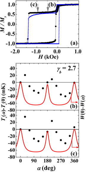
To compare the magnetic and superconducting properties of the sample, Fig. 10 also shows the magnetic hysteresis loop measured at 10 K and the angular dependences of at the magnetic field value Oe and 1 kOe. After the in-plane 4 kOe magnetic field cooling procedure the magnetizations of the Fe1 and Fe2 layers are aligned parallel . The Fe1 layer is fixed in a certain direction. The magnetization of the Fe2 layer is free and can be rotated by a small magnetic field starting from its saturation field value of Oe. To be completely sure that we exceed the saturation field we used the field strengths Oe (b) and 1000 Oe (c) for the rotation of the Fe2 layer magnetization. Certainly, the assumption that the magnetization of the Fe1 layer does not deviate from its initial position during the magnetic field rotation has to be checked more carefully. A slight deviation of the Fe1 layer magnetization from its initial field-cooling orientation is possible even at 500 Oe rotating field. In addition the maxima in the angular dependence occur at the angles which do not coincide with collinear configuration of magnetizations. In Section VI we introduce corrections to angle . In particular, we consider the anisotropy produced in the Fe1 layer by a contact with antiferromagnetic CoOx layer as well as the deviation of the initial direction of magnetization of the Fe1 layer from the direction of the cooling field.
Figures 10(b) and 10(c) show a clear non-monotonic dependence of on the angle . The minimum in occurs at noncollinear configuration of magnetizations. In order to characterize the magnitude of the triplet spin valve effect let us introduce the value . Fig. 11 shows the dependence of this value on the Fe2-layer thickness. One can see from this figure that the results for
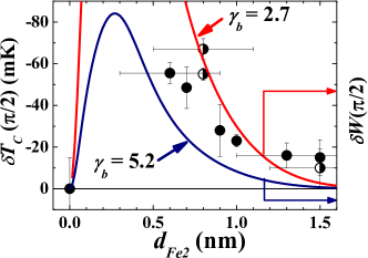
the set of samples based on the stabilized interface Fe/Cu/Pb (half-opened circles) reproduce the results for Fe/Pb (closed circles). The rises up to 67 mK when the decrease down to 0.8 nm. An increase of leads to a decrease of the effect. The physics of this decrease is obviously related to the suppression of the singlet components’ amplitude at the Fe1/Fe2 interface which serves as a source for the triplet components. We recall that the characteristic depth of the decay of the singlet component function in the F layer is small, nm. Therefore the strongest effect is expected for the smallest thickness .
VI Theory and discussion
Let us start from the theoretical model Fominov2 which we use for the analysis of our experimental results. The authors of this model have studied the critical temperature of an F/F/S trilayer at an arbitrary angle between the in-plane magnetizations, which makes it necessary to take the LRTC into account. They reduce the problem to the form which allows to apply a general numerical method developed in Ref. Fominov3 . The dirty limit was considered which was described by the Usadel equations. The linearized Usadel equations contain only the anomalous Green function. The boundary conditions for this function at the S/F interface contain the material matching parameter and the transparency parameter defined as:
| (5) |
Here and are the normal-state resistivities of the S and F layers; is the normal-state resistance of the S/F boundary; is its area; the coherence length in the S and F layers and are determined by Eqs. (3) and (4). The value of corresponds to the fully transparent S/F interface.
From the measured values of the residual resistivity of S and F layers and the values of (Eq. (2)) estimated from Pippard relations (Eq. (1)) we calculate the parameters of the studied systems presented in rows 1-13 of the Table 1.
| No. | Parameter | Fe/Pb | Fe/Cu/Pb |
| 1 | , cm | 1.47 | 1.47 |
| 2 | , cm/s | 1.8 | 1.8 |
| 3 | , cm2/s | 300 | 300 |
| 4 | , cm2/s | 100 | 100 |
| 5 | , nm | 42 | 42 |
| 6 | , nm | 17 | 17 |
| 7 | , cm | 10 | 10 |
| 8 | , cm/s | 108 | 108 |
| 9 | , cm2/s | 10 | 10 |
| 10 | , cm2/s | 3.3 | 3.3 |
| 11 | , nm | 7.5 | 7.5 |
| 12 | , nm | 1.0 | 1.0 |
| 13 | 0.78 | 0.78 | |
| 14 | 5.2 | 2.7 |
We start our theoretical analysis from the dependences at the fixed value of nm shown in Fig. 5. At large Pb-layer thickness, slowly decreases with decreasing . Below and 35 nm for Fe/Cu/Pb and Fe/Pb, correspondingly, the decreases abruptly; at nm and nm, respectively, superconductivity vanishes (1.5 K is the minimum temperature in our experimental setup).
The theory assumes the dirty-limit conditions for both F and S layers: . The critical thickness of the S layer is defined as the thickness below which there is no superconductivity in the S/F bilayer: . In accordance with the theory Fominov3 the explicit result for can be obtained in the limit as
| (6) |
where is the Euler constant. Fig. 5 shows that for the Fe/Pb bilayers nm and for the Fe/Cu/Pb system nm. Thus, for the Fe/Pb bilayer we obtain and for Fe/Cu/Pb . In accordance with Eqs. (5) and (6) we get for Fe/Pb and for Fe/Cu/Pb . These values are presented in row 14 of Table 1. Using these values we obtain theoretical fits shown in Fig. 5 in accordance to the theory Fominov3 . Thus all parameters of the studied samples are already determined from our transport measurements together with the data on the critical thickness of the S layer . At the same time, the dirty-limit conditions also require and , while all these length scales turn out to be of the same order for our samples. Therefore, the dirty-limit proximity theories Fominov3 ; Fominov2 are at the border of their applicability and while we expect them to capture basic qualitative features of our experimental results, the adequate quantitative analysis of our measurements in the framework of those theories is not guaranteed. So, the purpose of our theoretical analysis is to describe general qualitative tendencies that the experiment demonstrates.
Now we analyze consistently our experimental results on the full structures. Indeed, as it was supposed in Section V A, the shift of dependence for the Fe/Pb system in comparison with the Fe/Cu/Pb system is caused by the lower interface quality in the former case. The pair-breaking effect of the magnetic part and hence the strongly depend on the S/F interface quality. The effect is strongest for the interface of a good quality since Cooper pairs can easily penetrate from the S to the F part of the structure, where they experience the pair-breaking effect of the exchange field. A good S/F interface quality should therefore generally lead to the maximized effect of the suppression. In the opposite limit of an almost impenetrable interface, the Cooper pairs remain in the S layer and the pair-breaking effect is absent, hence is expected to be maximized.
The quality of the interface depends on several parameters. The most obvious one is the interface transparency for the electrons. The mutual interaction of two contacting layers depends also on the matching of conductivities (the condition for the derivatives of the Green function in the Kupriyanov-Lukichev boundary conditions KL ) and matching of the Fermi surfaces. Mismatches of this sort influence the transmission of electrons through the interface.
Let us start the numerical analysis of our results. In Ref. Fominov2 , the anomalous Green function was expanded in the basis of the Pauli matrices , and the unity matrix . It can be shown that in the case of in-plane magnetizations, the solution has the form
| (7) |
The component is real, while and are imaginary. The order parameter only enters the equation for the component. Calculations show that the effective boundary condition for reads
| (8) |
All information about the F layers is contained in a single function . Knowledge of is already sufficient to draw general conditions about the behavior of . Qualitatively it can be concluded that the larger , the stronger is suppressed. Thus, qualitative features of F1/F2/S spin valve system can be understood from calculation of . It is necessary to note that the real fitting is done in Fig. 5 only. In other cases we do not even plot but only , which does not take into account the parameters of the superconducting layer.
First, we analyze theoretically the experimental data shown in Fig. 5. The estimated values of we used as a starting point in optimization of the fitting the theory to the experimental results. One can see from Fig. 5 that the theory fits experimental data well. As it was expected, the intermediate Cu layer improves the interface transparency parameter from up to Note1 .
The second step was to apply these microscopic parameters for a theoretical analysis. Our theoretical model is based on the triplet spin valve model by Fominov et al. Fominov2 and is extended to the case of finite S/F transparency. Thus, in Figs. 8 and 7 the experimental dependence of on and can be described by the dependence of on and , respectively. At the same time the angular dependence depicted in Fig. 10 is expected to correlate with . The amplitude of the triplet spin valve effect in Fig. 11 is expected to correlate with .
The results in Fig. 10 were obtained using operating magnetic fields of 0.5 kOe (b) and 1 kOe (c). This means that at the rotating field of 1 kOe the magnetization of the fixed Fe1 layer may slightly change its direction comparing with the initial one. In this case the true angle between and differs from the rotation angle of the magnetic field.
We took this effect into account by applying a simple model which assumes an AF/F1/F2 sandwich with two uncoupled ferromagnetic films F1 and F2 in a rotating magnetic field. The magnetization of the F2 film is completely free and follows the rotating field direction. The F1 film has uniaxial anisotropy produced by a contact with antiferromagnetic film AF (see Meiklejohn ). The energy function for the F1 layer reads as follows:
| (9) |
Here is its magnetic moment, is the external rotating magnetic field, is the angle between and the easy axis produced by the antiferromagnetic layer, is the angle between and the easy axis. and are the uniaxial and unidirectional anisotropy constants, respectively. It is necessary to note that is much larger than that for a single Fe layer because of the proximity to the antiferromagnet. In its turn, is determined by the exchange bias caused by the antiferromagnet. Minimizing at a given direction of the external field, we find deviation of the magnetization from the easy axis. The true angle between the magnetizations of the Fe1 and Fe2 layers is then given by . The best simulation of the hysteresis loop in Fig. 10 (a) is depicted by the dotted blue curve. The result of this simulation was used to determine the real value for the angular dependences. This effect leads to distortion of the angular dependence of but does not shift and positions.
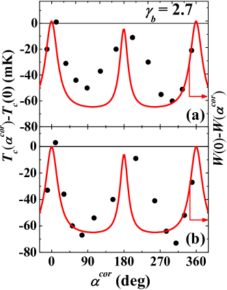
However, experimentally the maxima have offsets from these positions. This implies a possible existence of the real difference between the direction of the cooling field and the direction of the magnetization of the Fe1 layer. To check such a possibility we have performed ferromagnetic resonance (FMR) measurements of the sample CoOx/Fe1/Cu/Fe2/Cu using a standard X-band (10 GHz) electron spin resonance spectrometer. The FMR data at room temperature show that the in-plane easy axis which does not coincide with the long side of the rectangular shaped sample does exist already. Upon cooling the sample in an external field directed along the long side of the rectangular shaped samples (as we for the data shown in Fig. 10) the magnetization of the Fe1 layer deviates from the direction of the cooling field by 5-10 degrees. We suppose that the easy axis of the magnetization is induced by residual magnetic field in our vacuum system during the preparation process. Actually, the shift of the angle by 8 degrees and corrections of this angle according to Eq. (9) leads to a certain improvement of the agreement between theory and experiment. The dependence on the corrected angle is shown in Figs. 12a and 12b. Now the maxima of the experimental angular dependence coincide with P () and AP () configuration of magnetizations.
The analysis of the fitting results demonstrates the following. One can see from Fig. 5 that the theory fits the experimental data well. The theoretical curves in terms of the function shown in Figs. 7 and 8 correlate with experimental and dependencies. However, in contrast to the case of Fig. 5 where the experimental data evidence obviously the improvement of the quality of the S/F interface, the experimental results shown in Figs. 7 and 8 do not indicate such an improvement. In fact this is not surprising. The -suppression in the S/F structures is the first order effect in contrast to the case of other small effects like the superconducting spin valve effect.
Since the experimental results concern the S/F low-quality interface (Fe/Pb) and the S/F high-quality interface (Fe/Cu/Pb) we will mainly focus on two simulation curves with the low and high S/F interface quality, respectively. The analytical results for are very bulky so we will not depict them in this paper. Calculations of the microscopic parameters and 2.7 which were obtained using the results in Fig. 5 fit experimental data satisfactory. All parameters of the theory were obtained from the normal-state transport properties of the Pb and Fe layers (=42 nm, =17 nm, =7.5 nm and =1 nm) and using the results in Fig. 5 (=5.2 and 2.7). Having compared all experimental data shown in Figs. 7, 8, 11 and 12 with the theoretical results we can conclude that the general tendencies of the experimental dependences are reproduced by the theory. According to theoretical calculations shown in Fig. 11, the degradation of the quality of the interface and therefore an increase of leads to the reduction of the triplet spin valve effect amplitude. This means that the introduction of the Cu intermediate layer between the Pb and Fe layers not only stabilizes the S/F interface but also increases its quality. This conclusion is further confirmed by the results depicted in Fig. 5. For the bilayer Fe/Pb systems the introduction of a thin Cu (1.2 nm) film between the Fe and Pb layers leads to a dramatic drop of the . This difference can be easily described by an improvement of the F/S interface transparency which is expressed by decreasing the value from 5.2 down to 2.7.
VII Summary
By introducing an intermediate thin Cu layer between the ferromagnetic Fe2 and the superconducting Pb layer in the superconducting spin valve heterostructure CoOx/Fe1/Cu/Fe2/Cu/Pb we have substantially improved its stability and operational performance. The crucial role of the intermediate Cu layer is that it prevents material interdiffusion process and increases electron transparency between the Fe2 and Pb layers as compared to the previously studied CoOx/Fe1/Cu/Fe2/Pb heterostructure. Such an improvement has made possible a comprehensive study of the physical properties of the spin valve and performing a microscopic analysis of the data beyond the limitations of the previous studies. All microscopic parameters were obtained from the normal state transport properties and from the values of the critical thickness of the S layer. The obtained realistic parameters of the high quality spin valve heterostructures enable to reproduce theoretically both the ordinary spin valve effect and the effect of the generation of the long-range triplet component of the superconducting condensate in agreement with our experimental observations. In particular, our results validate the theoretical description of the long-range triplet component of the superconducting condensate on a qualitative level.
Acknowledgements.
This work is supported by DFG (Grant. No. LE 3270/1-1). It was also partially supported by RFBR (Grants No. 13-02-01389-a and 14-02-00350-a), by Programs of the RAS, by the Ministry of Education and Science of the Russian Federation, and the program “5top100”.References
- (1) S. Oh, D. Youm, M. R. Beasley, Appl. Phys. Lett. 71, 2376 (1997).
- (2) P. V. Leksin, N. N. Garif’yanov, I. A. Garifullin, J. Schumann, H. Vinzelberg, V. Kataev, R. Klingeler, O. G. Schmidt, and B. Büchner, Apl. Phys. Lett. 97, 102505 (2010).
- (3) P. V. Leksin, N. N. Garif’yanov, I. A. Garifullin, J. Schumann, V. Kataev, O. G. Schmidt, and B. Büchner, Phys. Rev. Lett. 106, 067005 (2011).
- (4) P. V. Leksin, N. N. Garif’yanov, I. A. Garifullin, J. Schumann, V. Kataev, O. G. Schmidt, and B. Büchner, Phys. Rev. B 85, 024502 (2012).
- (5) Ya. V. Fominov, A. A. Golubov, T. Yu. Karminskaya, M. Yu. Kupriyanov, R. G. Deminov, and L. R. Tagirov, Pis’ma Zh. Eksp. Teor. Fiz. 91, 329 (2010) [JETP Lett. 91, 308 (2010)].
- (6) F. S. Bergeret, A. F. Volkov, K. B. Efetov, Phys. Rev. Lett. 86, 4096 (2001).
- (7) P. V. Leksin, N. N. Garif’yanov, I. A. Garifullin, Ya. V. Fominov, J. Schumann, Y. Krupskaya, V. Kataev, O. G. Schmidt, and B. Büchner, Phys. Rev. Lett. 109, 057005 (2012).
- (8) J. Bardeen, L. N. Cooper, J. R. Schrieffer, Phys. Rev. 106, 162 (1957); 108, 1175 (1957).
- (9) Z. Radović, L. Dobrosavljević-Grujić, A. I. Buzdin, and J. R. Clem, Phys. Rev. B 38, 2388 (1988).
- (10) L. Lazar, K. Westerholt, H. Zabel, L. R. Tagirov, Yu. V. Goryunov, N. N. Garif’yanov and I.A. Garifullin. Phys. Rev. B 61, 3711 (2000).
- (11) Ya. V. Fominov, A. A. Golubov, and M. Yu. Kupriyanov, Pis’ma Zh. Eksp. Teor. Fiz. 77, 609 (2003) [JETP Lett. 77, 510 (2003)].
- (12) A. I. Buzdin, Rev. Mod. Phys. 77, 935 (2005).
- (13) L. R. Tagirov, Phys. Rev. Lett. 83, 2058 (1999).
- (14) A. I. Buzdin, A. V. Vedyaev. and N. N. Ryzhanova, Europhys. Lett. 48, 686 (1999).
- (15) I. Baladié, A. Buzdin, N. Ryzhanova, and A. Vedyayev, Phys. Rev. B 63, 054518 (2001).
- (16) J. Y. Gu, C. Y. You, J. S. Jiang, J. Pearson, Ya. B. Bazaliy, S. D. Bader, Phys. Rev. Lett. 89, 267001 (2002).
- (17) C.-Y. You, Ya. B. Bazaliy, J. Y. Gu, S.-J. Oh, L. M. Litvak, and S. D. Bader, Phys. Rev. B 70, 014505 (2004).
- (18) A. Potenza, C. H. Marrows, Phys. Rev. B 71, 180503 (2005).
- (19) V. Pen̂a, Z. Sefrioui, D. Arias, C. Leon, J. Santamaria, J. L. Martinez, S. G. E. te Velthuis, A. Hoffmann, Phys. Rev. Lett. 94, 057002 (2005).
- (20) I. C. Moraru, Jr. W. P. Pratt, N. O. Birge, Phys. Rev. Lett. 96, 037004 (2006); Phys. Rev. B 74, 220507(R) (2006).
- (21) Guo-Xing Miao, Ana V. Ramos, and J. S. Moodera. Phys. Rev. Lett. 101, 137001 (2008).
- (22) K. Westerholt, D. Sprungmann, H. Zabel, R. Brucas, B. Hjörvarsson, D. A. Tikhonov, I. A. Garifullin, Phys. Rev. Lett. 95, 097003 (2005).
- (23) G. Nowak, H. Zabel, K. Westerholt, I. Garifullin, M. Marcellini, A. Liebig, B. Hjörvarsson, Phys. Rev. B 78, 134520 (2008).
- (24) G. Nowak, K. Westerholt, H. Zabel, Supercond. Sci. Technol 26, 025004 (2013).
- (25) Yu. N. Proshin, A. Zimin, N. G. Fazleev, M. G. Khusainov, Phys. Rev. B 73, 184514 (2006).
- (26) M. V. Avdeev, Yu. N. Proshin, Zh. Eksp. Teor. Fiz. 144, 1251 (2013) [JETP, 117, 1101 (2013)].
- (27) M. V. Avdeev, S. L. Tsarevskii, Yu. N. Proshin, Journ. Korean Phys. Soc. 63, 466 (2013).
- (28) A. F. Volkov, F. S. Bergeret, and K. B. Efetov, Phys. Rev. Lett., 90, 117006 (2003).
- (29) M. Houzet and A. I. Buzdin, Phys. Rev. B 76, 060504(R) (2007).
- (30) M. Eschrig, Phys. Today 64, 43 (2011).
- (31) A. S. Mel’nikov, A. V. Samokhvalov, S. M. Kuznetsova, A. I. Buzdin, Phys. Rev. Lett. 109,237006 (2012).
- (32) W. Booniad, P. Udomsamuthiruis, Physica C: Superconductivity 502, 41 (2014).
- (33) F. S. Bergeret, A. F. Volkov, K. B. Efetov, Rev. Mod. Phys., 77, 1321 (2005).
- (34) K. B. Efetov, I. A. Garifullin, A. F. Volkov, K. Westerholt, Magnetic Heterostructures. Advances and Perspectives in Spinstructures and Spintransport. Series Springer Tracts in Modern Physics. V. 227. Berlin. Springer, 2007. P. 252. [arxiv: cond-mat/0610708v2].
- (35) K. B. Efetov, I. A. Garifullin, A. F. Volkov, and K. Westerholt, Magnetic Nanostructures. Spin Dynamic and Spin Transport. Series Springer Tracts in Modern Physics Vol. 246, Hartmut Zabel, Michael Farle. (Eds.), Springer-Verlag Berlin Heidelberg, 2013. P. 85-118.
- (36) M. Giroud, H. Courtois, K. Hasselbach, D. Mailly, B. Pannetier, Phys. Rev. B 58, R11872 (1998).
- (37) V. T. Petrashov, I. A. Sosnin, I. Cox, A. Parsons, and C. Troadec, Phys. Rev. Lett. 83, 3281 (1999).
- (38) C. Visani, Z. Sefrioui, J. Tornos, C. Leon, J. Briatio, M. Bibes, A. Barthelemy, J. Santamaria, Javier E. Villegas, Nature Phys. 8, 539 (2012).
- (39) I. Sosnin, H. Cho, V. T. Petrashov, and A. F. Volkov, Phys. Rev. Lett. 96, 157002 (2006).
- (40) R. S. Keizer, S. T. B. Goennenwein, T. M. Klapwijk, G. Miao, G. Xiao, and A. Gupta, Nature 439, 825 (2006).
- (41) J. Wang, M. Singh, M. Tian, N. Kumar, B. Liu, C. Shi, J. K. Jain, N. Samarth, T. E. Mallouk, and M. H. W. Chan, Nature Physics 6, 389 (2010).
- (42) J. W. A. Robinson, J. D. S. Witt, and M. G. Blamire, Science 329, 59 (2010).
- (43) M. S. Anwar, F. Czeschka, M. Hesselberth, M. Porcu, and J. Aarts, Phys. Rev. B 82, 100501 (2010).
- (44) T. S. Khaire, M. A. Khasawneh, W. P. Pratt, Jr., and N. O. Birge, Phys. Rev. Lett. 104, 137002 (2010).
- (45) D. Sprungmann, K. Westerholt, H. Zabel, M. Weides, and H. Kohlstedt, Phys. Rev. B 82, 060505 (2010).
- (46) V. I. Zdravkov, J. Kehrle, G. Obermeier, D. Lenk, H.-A. Krug von Nidda, C. Müller, M. Yu. Kupriyanov, A. S. Sidorenko, S. Horn, R. Tidecks, and L. R. Tagirov Phys. Rev.B, 87, 144507 (2013).
- (47) X. L. Wang, A. Di Bernardo, N. Banerjee, A. Wells, F. S. Bergeret, M. G. Blamire, and J. W. A. Robinson, Phys. Rev. B 89,140508 (2014).
- (48) P. V. Leksin, A. A. Kamashev, N. N. Garif’yanov, I. A. Garifullin, Ya. V. Fominov, J. Schumann, C. Hess, V. Kataev, and B. Büchner, Pis’ma Zh. Eksp. Teor. Fiz. 97, 549 (2013) [JETP Lett. 97, 478 (2013)].
- (49) C. Kittel. Introduction to Solid State Physics (Willey, New York, 1976), p. 266.
- (50) A. Pippard, Rep. Prog. Phys. 23, 176 (1960).
- (51) G. Deutscher, J. Bok, Chin. J. Phys. 31, 805 (1993).
- (52) Ya. V. Fominov, N. M. Chtchelkatchev, and A. A. Golubov, Phys. Rev. B 66, 014507 (2002).
- (53) M. Yu. Kuprianov and V. F. Lukichev, Zh. Eksp. Teor. Fiz. 94, 139 (1988) [Sov. Phys. JETP 67, 1163 (1988)].
- (54) In the previous work Lazar for Fe/Pb/Fe trilayers prepared using rf sputtering method has been found. However, the characteristic width of the superconducting transition curves for these samples amounted to 150-200 mK. Such a high value of makes it complicated to study small shifts in range of 50 - 70 mK which are due to the investigated effects, e.g. superconducting spin valve effect.
- (55) W. H. Meiklejohn, C. P. Bean, Phys. Rev. 105, 3 (1956).