Matter-wave laser Interferometric Gravitation Antenna (MIGA):
New perspectives for fundamental physics and geosciences
Abstract
The MIGA project aims at demonstrating precision measurements of gravity with cold atom sensors in a large scale instrument and at studying the associated applications in geosciences and fundamental physics. The first stage of the project (2013-2018) will consist in building a 300-meter long optical cavity to interrogate atom interferometers and will be based at the low noise underground laboratory LSBB in Rustrel, France. The second stage of the project (2018-2023) will be dedicated to science runs and data analyses in order to probe the spatio-temporal structure of the local gravity field of the LSBB region, a site of high hydrological interest. MIGA will also assess future potential applications of atom interferometry to gravitational wave detection in the frequency band Hz hardly covered by future long baseline optical interferometers. This paper presents the main objectives of the project, the status of the construction of the instrument and the motivation for the applications of MIGA in geosciences. Important results on new atom interferometry techniques developed at SYRTE in the context of MIGA and paving the way to precision gravity measurements are also reported.
1 Introduction
After more than 20 years of fundamental research, atom interferometers (AIs) have reached sensitivity and accuracy levels competing with or beating inertial sensors based on different technologies. Atom interferometry offers interesting applications in geophysics (gravimetry, gradiometry, Earth rotation rate measurements), inertial sensing (submarine or aircraft autonomous positioning), metrology (new definition of the kilogram) and fundamental physics (tests of the standard model, tests of general relativity). AIs already contributed significantly to fundamental physics by, for example, providing stringent constraints on quantum-electrodynamics through measurements of the hyperfine structure constant [1], testing the Equivalence Principle with cold atoms [2], or providing new measurements for the Newtonian gravitational constant [3]. Cold atom sensors have been established as key instruments in metrology for the new definition of the kilogram [4] or through international comparisons of gravimeters [5]. The field of atom interferometry is now entering a new phase where very high sensitivity levels must be demonstrated, in order to enlarge the potential applications outside atomic physics laboratories. These applications range from gravitational wave (GW) detection in the frequency band to next generation ground and space-based Earth gravity field studies to precision gyroscopes and accelerometers.
The Matter-wave laser Interferometric Gravitation Antenna (MIGA) project will explore the use of atom interferometry techniques to build a large-scale matter-wave sensor which will open new applications in geoscience and fundamental physics. The MIGA consortium gathers 15 expert French laboratories and companies in atomic physics, metrology, optics, geosciences and gravitational physics, with the aim to build a large-scale underground atom-interferometer instrument by 2018 and operate it till at least 2023. In this paper, we present the main objectives of the project, the status of the construction of the instrument and the motivation for the applications of MIGA in geosciences. Important results on new atom interferometry techniques developed at SYRTE in the context of MIGA and paving the way to precision gravity measurements are also reported.
2 MIGA principle and sensitivity
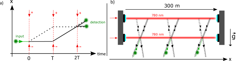
The AI geometry of MIGA is similar to the one of a Mach-Zehnder Interferometer for optical waves. The geometry is described in Fig. 1a) where matter waves are manipulated by a set of counter-propagating laser pulses. At the input of the interferometer, a pulse creates an equiprobable coherent superposition of two different momentum states of the atom. The matter-waves are then deflected by the use of a pulse before being recombined with a second pulse. To realize these beam-splitters and mirror pulses, MIGA will make use of Bragg diffraction of matter-waves on light standing waves [6]. Conservation of energy-momentum during this process imposes to couple only atomic states of momentum to state where is the wave vector of the interrogation field. At the output of the interferometer, the transition probability between these states is obtained by a two waves interference formula . The atom phase shift depends on the phase difference between the two couterpropagating lasers which is imprinted on the diffracted matter-wave during the light pulse. MIGA will make use of a set of such AIs interrogated by the resonant field of an optical cavity as described in Fig. 1b). In this configuration, each AI will measure the inertial effects along the cavity axis at position together with GW effects associated to the cavity propagation of the interrogation laser. Spurious effects such as fluctuations of the cavity mirror position and or laser frequency noise also affect the AI signal. Taking into account these different effects, the atom phase shift measured by the AI at position reads:
| (1) |
where is the GW strain amplitude, is the mean cavity length and accounts for the convolution of the time-fluctuations of effect by the AI sensitivity function [7]. The last term in Eq. (1) accounts for the acceleration of the center of mass of the free falling atom cloud which depends on the local position of the AI because of the non-homogeneous gravitational field. Common mode rejection between the AI signals at different positions will enable to cancel out most of the contribution of cavity mirror position fluctuations . The influence of laser frequency noise will be kept negligible in the first version of the MIGA instrument (till 2023) by using state-of-the-art ultra stable laser techniques, yielding relative stabilities better than . Eq. (1) thus shows that the instrument can be used for local monitoring of mass motion encoded in the last term and, in the future, for GW detection without being affected by position noise of the optics.
The last term of Eq. (1) can be written as where is the local acceleration of gravity of the atoms at position and is the time between the light pulses in a 3 light pulse geometry (see Fig. 1a)). For two AIs separated by the baseline and assuming a constant gravity gradient , the gradiometer sensitivity of the instrument is given by where is the AI phase sensitivity and the integration time. For , a shot-noise limited AI with atoms (1 mrad phase sensitivity) and yields a gradiometer sensitivity of after of integration time, sufficient to detect a mass anomaly of few tons in a 100 meter region around the instrument. Combining the different measurements provided by the array of AIs will bring to a more precise measurement of the mass anomaly position and potentially movement.
3 MIGA subsystems
3.1 Cold atom source
The atom source unit delivers cold atom clouds which will be interrogated by the MIGA cavity Bragg beams to form the AI. The general design of the unit is presented in Fig. 2. Its main functions are (i) the loading and laser cooling of atoms, (ii) the launching of the atomic cloud along a quasi-vertical trajectory and the control of the angle of the trajectory with respect to the cavity beams, (iii) the preparation of the cold atom source before it enters the interferometer, and (iv) the detection of the atoms at the interferometer output.
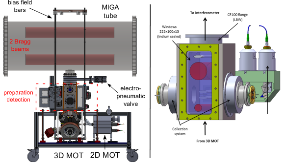
In order to optimize the contrast of the AI, the quantum state of the atoms is prepared on their way up, before the interrogation region. A first counter-propagating velocity-selective Raman pulse (bottom red beam in Fig. 2) is used to select the atoms in the Zeeman sub-level of the hyperfine state, with a relatively narrow velocity class (width of 1 photon recoil, corresponding to a temperature of nK in the direction of the Raman lasers). The unselected atoms are then pushed by a laser tuned on resonance with the cycling transition. This Raman/push procedure is repeated a second time to clean the remaining unwanted atoms produced by spontaneous emission on the first Raman selection pulse. For this purpose, we use the Raman 2 beam (top big red beam) with approximately the same duration and Rabi frequency as the Raman 1 beam to transfer the atoms back to the state. The remaining atoms in the state are pushed with an orthogonal push beam tuned on the transition (gray beam at the top). The angle of the Raman beams can be tuned by few degrees around zero in order to introduce a Doppler effect which allows lifting the degeneracy between the and transitions. In this way, the atoms will enter the interferometer in a well-defined momentum state. Moreover, the Raman beam angle enables to control the angle of the trajectory with respect to the vertical direction, i.e. the Bragg angle. After this all-optical preparation steps, the atoms enter the interferometer in the internal state, with a relatively narrow velocity distribution in the longitudinal direction of the Bragg interrogation beams and with a well-controlled trajectory.
After their interrogation by the Bragg beams in the AI, the two different momentum states of the atoms are labelled to two different internal states with the Raman 2 laser. More precisely, the velocity selective feature of the Raman transition is used to transfer the atoms to the internal state, while the atoms remain in the internal state. The atoms can then be resolved with common fluorescence techniques. Detection of the atoms labelled in is first realized with a light sheet beam (see Fig. 2) tuned on resonance on the transition. The beam is partially blocked at the retroreflection mirror so that the atoms acquire a net momentum in the beam direction and will therefore not be resonant with the following light beams. The atoms are re-pumped to the state using a thinner intermediate light sheet, before these atoms enter the third light sheet. The fluorescence light of the two light sheets is collected by a collection efficiency lens and imaged on a photodiode. The fluorescence signal is used to reconstruct the normalized atomic populations and then the transition probability, yielding the AI phase.
3.2 Laser System.
The different lasers used to cool and manipulate the atoms are delivered from an all-fibered laser module developed by the company Quans [8]. The laser architecture is based on frequency doubled telecom lasers, as already described in various publications, see e.g. Ref. [9]. A Master laser is locked using a Rubidium 85 saturated absorption spectroscopy signal and references 3 slave diodes which are respectively used for the 2D MOT cooling laser, the 3D MOT cooling/Raman 2 laser, and the 3D MOT repumper/Raman 1 laser. The 3 slave diodes are all phase locked to the Master laser. The repumping light for the 2D MOT is generated by a fiber electro-optic phase modulator at 1560 nm fed with the appropriate microwave frequency.
After amplification in Erbium doped fiber amplifiers and second harmonic generation in PPLN waveguide crystals, the 780 nm light is sent to optical splitters and guided to the experiment chamber using several optical fibers. The laser module nominally delivers 170 mW total power for the 2D MOT, 150 mW total power for the 3D MOT, and in each of the two Raman beam couple, used for the preparation stage and the detection respectively. The power and polarization fluctuations at the fiber outputs are close to the one percent level. The phase lock signals are controlled by radio and microwave frequency sources all referenced to a stable 100 MHz oscillator. The full laser system is hosted in a transportable rack.
3.3 Optical cavity setup
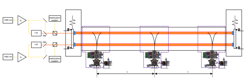
The intensity of the Bragg pulses is enhanced thanks to two cavities, one for the splitting and projection /2 pulses, and one at the trajectories’ apogee for the pulse. The solution adopted to have the 780 nm interrogation pulses at resonance with the cavities relies on obtaining the probe radiation via frequency doubling of a telecom laser at 1560 nm continuously locked to one of the two resonators to track its length variations. The servo system is used also to control the payload tilts and rotations so as to maintain the phase coherence between the two cavities. The Bragg pulses are shaped with acousto-optic modulators (AOMs) on the two beams at 780 nm before their injection in the cavities. The telecom laser is phase modulated and locked to the cavity on one frequency sideband, and the modulation frequency is chosen so as to have the doubled component of the carrier resonant with the resonator. has to account for the different cavity length at 780 nm and 1560 nm, because of the refraction index of the two coatings on the mirrors, as well as for the frequency shift imposed by the AOM used to pulse the interrogation beams. The LP2N laboratory is currently developing a prototype system using low power laser sources (100 mW at 1560 nm, and 1 W at 780 nm). The CELIA laboratory at Bordeaux 1 University is developing a high power solution, which targets 100 W of radiation at 780 nm before the injection in the cavity.
The two cavities share a common payload on each side to hold the mirrors, placed at a vertical distance of cm to have an interrogation time . The impact of ground seismic noise on the position of the cavity mirrors will be reduced by way of an anti-vibration system, which must limit the related phase noise contribution on each AI. Two different approaches are being considered: a passive system of mechanical filters to suspend each payload, and an active stabilization of each mirror position using piezoelectric actuators. The main constraints on the system are set by the level of the seismic noise at the installation site (LSBB), and the response function of the AIs to mirror acceleration noise, as in Eq. (1).
4 High sensitivity atom interferometry techniques
The performance of the MIGA antenna will rely on the possibility to achieve high sensitivity gravito-inertial measurements. Moreover, future applications to gravitational wave detection will require higher bandwidth () cold AIs than what is currently obtained in laboratories (about for long AIs). In this section, we briefly present two results obtained at the SYRTE laboratory on an AI which geometry is similar to the fountain-like architecture of the MIGA sensors.
First, we demonstrated a new method to interrogate several clouds of cold atoms simultaneously in the interferometer in a so-called joint interrogation scheme [10] (the principle of the joint interrogation is represented in Fig. 4, left panel). Conventional cold AIs run in sequential mode: after laser cooling, the cold atoms are injected in the interferometer where the inertial effects are measured. Thus, the sensor does not operate continuously. Information on signals varying during the cold atom source preparation is lost, which is a major drawback for various applications. Moreover, the aliasing effect of the vibration noise associated with the dead time results in a degradation of the short term sensitivity. To circumvent this problem, the joint interrogation solution compatible with the MIGA fountain geometry allows interrogating the atoms in the interferometer region, while another cold atom cloud is being prepared. This leads to a zero-dead time gyroscope. Moreover, if the different atom clouds share common (Bragg) interrogation pulses, the vibration noise is correlated between the successive measurements, which leads to a faster averaging of the vibration noise. We demonstrated a multiple joint operation in which up to five clouds of atoms were interrogated simultaneously in a single fountain with interrogation time [10]. The essential feature of the multiple joint operation, which we demonstrated for a micro-wave Ramsey interrogation is currently being generalized to the inertial sensor operation. The multiple joint operation gives access to high-frequency components while maintaining high sensitivity linked to long interaction times achievable with cold atom sensors.
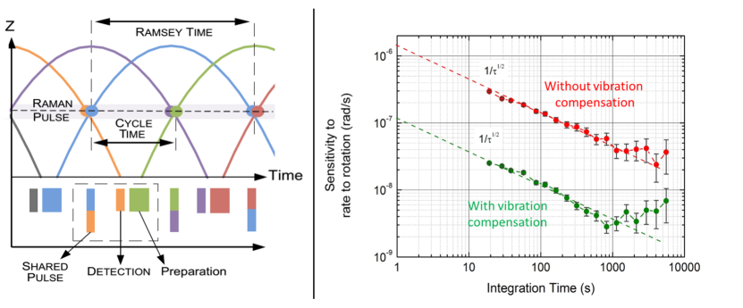
A second key feature of MIGA will be to operate an AI with a long interrogation time, , yielding a high accelerometer scale factor . In this regime, the effect of vibrations from the payload results in several radians of AI phase noise and must be managed to keep it below the targeted phase sensitivity level (ideally below the atom shot noise of ). In the MIGA gradiometer configuration the vibration noise is partially common to the different AIs, so the differential phase can be obtained by adopting specific retrieval methods [13, 14]. Nevertheless, the extraction of the interferometric phase still requires the AI to be operated in its linear range, i.e. . Moreover, being able to extract the individual AI phase yields the absolute local gravity field in the direction of the Bragg beams and therefore provides additional information to the gravity gradient and its curvature. To this end, we demonstrated in the SYRTE experiment the possibility to reject the vibration noise with a factor up to 20 using classical accelerometers in an interferometer with interrogation time. This noise rejection was performed in a gyroscope configuration where the AI mainly senses rotation rates, allowing us to demonstrate a gyroscope with long term stability (see Fig. 4, right panel). These results strongly support the possibility to obtain high sensitivity gravity measurements with the MIGA interferometers.
5 MIGA: new perspectives in geosciences
5.1 Hydrological interest of the Fontaine de Vaucluse/LSBB site
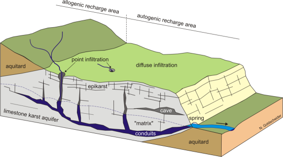
Almost a quarter of the world population obtains its drinking water from karst hydrosystems [15] (see Fig. 5 for a schematic). Efficient protection and sustainable management of such resources require appropriate tools and strategies to be developed [16]. The numerical modelling of karst aquifers is probably the major stumbling block in developing such tools. Karst remains aside from other hydrosystems, because the paroxysmal [17] and self-organized [18] heterogeneity of that medium limits the relevance of classical hydro-geological tools, such as physically-based and gridded flow models, and because of the difficulty of characterization of this heterogeneity. Hopefully, recent improvements of computing power and computational techniques in the one hand and geophysical measurement techniques in the other hand [19] enable considering now the applicability of physically-based and gridded flow models to karst hydrodynamics. Developing and calibrating such tools requires the acquisition of 4D hydro-geo-physical data (water content, flux and velocities, …) at different scales.
In south-eastern France, the Fontaine-de-Vaucluse karst hydrosystem is one of the biggest karst watershed in the world: its catchment area is around km2 and composed of a nearly 1500 m thick massive and continuous limestone [20] from Necomanian marls to upper Aptian marls. The Fontaine-de-Vaucluse spring is quite the only outlet of this hydrosystem and the biggest karst spring in Europe with an average outlet discharge of 19 m3/s between 1877 and 2004 [21]. Within this peculiar karst hydrosystem, LSBB (Low Noise Underground Research Laboratory) is an almost horizontal tunnel coming across the karst medium and intersecting arbitrarily faults, karst networks and flowpaths at depths between 0 and 519 m. All these elements make the Fontaine-de-Vaucluse and LSBB sites a relevant multi-scales observatory to develop physically-based and gridded flow models to karst hydrodynamics based on innovative 4D hydro-geo-physical data acquisition.
5.2 Methods
Whereas recent developments of geophysical methods enable to expect better characterization of complex hydrosystems [19], their application to karst remains not obvious [22]. Nevertheless, various conventional techniques and instruments are currently applied to karst hydro-geology such as Electrical Resistivity Tomography (ERT) and 2D Ground Penetration Radar (GPR). One of the important questions is to have enough resolution and depth of investigation all at once to detail all the features controlling the groundwater circulation and storage from matrix porosity or micro-fracturing to major faults and karst conduits . On the other hand, estimating the variation of water mass requires the use of integrating methods directly or indirectly related to water content such as seismic, ERT, Magnetic Resonance Sounding (MRS) or Gravimetry. For instance, as shown in Ref. [23], GPR results supply a near surface high resolution () imaging and thus can provide relevant geological information such as stratifications and fractures. However, GPR’s investigation depth remains limited to around 12 meters. ERT surveys shows strong lateral and vertical variations which can inform on general geological structuring and feature orientation. ERT is able to prospect down to 40 meters but is a low resolution integrative technique. Finally, active seismic reflection imaging or transmission tomography (at frequencies ) allows measuring the ground seismic velocities and probing the rock elasticity and porosity, yielding information on the rock structure and fractures [24]. The corresponding resolution is with accessible depth .
In contrast to these techniques requiring an inversion model, atom interferometry can provide direct measurements of the surrounding mass distribution and thus represents an interesting complementary method. Moreover, long-term (years) measurements of the gravity field can be obtained thanks to the long term stability of cold atom sensors. In this context, MIGA will provide non-invasive measurements of the gravity field on a few 100 m scale. As discussed in section 2, the typical gravity gradient sensitivity of MIGA will be after 100 s of measurement time, with a maximum sensitivity in the direction of the baseline. Such gravity gradients correspond for example to a 1 ton mass at 100 meter from the instrument. If the source mass producing such gravity gradients moves in time, the AI antenna signal will vary accordingly. The spatial resolution of the antenna will depend on the number of AIs and their relative distance. Tuning the AI geometry (interrogation time , number of pulses, etc.) allows changing the response of the sensor to the source mass and thus yielding more information.
6 Conclusion and perspectives
The MIGA instrument will use long baseline (300 m) optical and matter-wave interferometry for high precision gravity field measurements, in order to monitor subsurface mass transfers in the LSBB region, which represents a unique site of hydrological interest. Combining conventional instruments and methods from hydro-geology with cold atom gravitation sensor measurements will allow better modelling of karst aquifers, for which only very few (3+1)-dimensional data are currently available to constrain the models. MIGA will also investigate the applications of atom interferometry to extend the sensitivity of future GW detectors at frequencies below .
The first cold atom source unit has been characterized and will be installed at LP2N (Talence) in June 2015, where the first atom interferometry experiments in a 1 meter prototype optical cavity cavity will be performed. A 6 meter AI gradiometer prototype based at LP2N is currently under design and will allow testing at a reduced scale the measurement strategy for mass monitoring at LSBB. Digging of the galleries at LSBB is planned for 2016, with an installation of the 300 meter long vacuum cavity and the three AI units in 2017. Following the final optimizations of the instrument, the operation phase should start in 2018.
The MIGA Equipex aims at being the first step to a larger, more ambitious program that may lead to a future European infrastructure. The development, the scientific operation and the technical implementation of this first version of the gravitational antenna will pave the way to a more sensitive version that will take advantage of the current fundamental research in atom interferometry. The MIGA instrument and its envisioned evolution will be at the forefront of underground instrumentation in fundamental research and they will foster research in key quantum technologies. Beyond the development of this equipment, the results of the MIGA project will pave the way to enhancement technique for the low frequency sensitivity of future gravitational wave detectors.
Acknowledgments
The MIGA Equipex is funded by ANR under the program Investissement d’Avenir (ANR-11-EQPX-0028). We also thank funding from the city of Paris (Emergence project HSENS-MWGRAV), Délégation Générale pour l’Armement (DGA) and CNES.
References
References
- [1] R. Bouchendira et al., New determination of the fine structure constant and test of the quantum electrodynamics. Phys. Rev. Lett., 106:080801, Feb 2011.
- [2] D. Schlippert et al., Quantum test of the universality of free fall. Phys. Rev. Lett., 112:203002, May 2014.
- [3] G. Rosi et al., Precision measurement of the Newtonian gravitational constant using cold atoms. Nature, 510(7506):518–521, June 2014.
- [4] M. Thomas et al., First determination of the Planck constant using the LNE Watt balance. Metrologia, 52(2):433, 2015.
- [5] P. Gillot and et al. Stability comparison of two absolute gravimeters: optical versus atomic interferometers. Metrologia, 51(5):L15, 2014.
- [6] P. J. Martin et al., Bragg scattering of atoms from a standing light wave. Phys. Rev. Lett., 60:515–518, Feb 1988.
- [7] P. Cheinet et al., Measurement of the sensitivity function in time-domain atomic interferometer. IEEE Trans. on Instrum. Meas, 57:1141, 2008.
- [8] http://www.muquans.com/.
- [9] V. Ménoret et al., Dual-wavelength laser source for onboard atom interferometry. Opt. Lett., 36(21):4128–4130, Nov 2011.
- [10] M. Meunier et al., Stability enhancement by joint phase measurements in a single cold atomic fountain. Phys. Rev. A, 90:063633, Dec 2014.
- [11] I. Dutta, D. Savoie, B. Fang, R. Geiger, A. Landragin, in preparation.
- [12] B. Barrett et al., The Sagnac effect: 20 years of development in matter-wave interferometry. Comptes Rendus Physique, 15(10):875–883, December 2014.
- [13] F. Sorrentino et al., Simultaneous measurement of gravity acceleration and gravity gradient with an atom interferometer. Appl. Phys. Lett., 101:114106, 2012.
- [14] B. Barrett et al., Extracting the differential phase from dual-species matter-wave interferometers for weak equivalence principle tests. New J. Phys., 17:085010, 2015.
- [15] D. C. Ford and P. W. Williams, Karst hydrogeology and geomorphology,. John Wiley & Sons, Chichester., 2007.
- [16] M. Mudarra et al., Hydrochemical heterogeneity in the discharge zone of a karstic aquifer. In Environmental Earth Sciences, pages 163–168. Springer Berlin Heidelberg, 2010.
- [17] de Marsily, Méthodes et domaines d’application de la mécanique des fluides en milieux poreux et fissurés. Annales des Mines, 1984, 5-6, 5-10 (1984).
- [18] S. R. H. Worthington and D. C. Ford, Self-organized permeability in carbonate aquifers. Ground Water, 47(3):326–336, 2009.
- [19] B. Berkowitz, Characterizing flow and transport in fractured geological media: A review. Advances in Water Resources, 25:861–884, August 2002.
- [20] J. P. Masse, Les calcaires urgoniens de Provence ; Valanginien - Aptien inférieur ; Tome 1 : Stratigraphie - Paléontologie ; Tome 2 : Les paléoenvironnements et leur évolution. Thesis: Univ. d’Aix-Marseille, 445 p., 1976.
- [21] A. L. Cognard-Plancq et al., Historical monthly rainfall-runoff database on Fontaine de Vaucluse karst system : review and lessons. Proceedings of 3rd international symposium on karst “Groundwater in the Mediterranean Countries”, Malaga, Spain, IGME Publications, vol 18, pp 465-475, 2006.
- [22] K. Chalikakis et al., Contribution of geophysical methods to karst-system exploration: an overview. Hydrogeology Journal, 19:1169–1180, 2011.
- [23] S. D. Carrière et al., Combining electrical resistivity tomography and ground penetrating radar to study geological structuring of karst unsaturated zone. Journal of Applied Geophysics, 94(0):31–41, July 2013.
- [24] E. Maufroy et al., Travel time inversion from ground level to gallery: protocol for the characterization of P-wave seismic signature in a fractured-porous Urgonian platform at hectometric scale, Near Surface Geophysics Vol 12, No 6, December 2014 pp. 697 - 708.