jyotirmoy.deshmukh@tema.toyota.com rupak,vinayak@mpi-sws.org
Quantifying Conformance using the Skorokhod Metric ††thanks: This research was funded in part by a Humboldt foundation grant, FCT grant SFRHBPD902672012, and by a contract from Toyota Motors.
Abstract
The conformance testing problem for dynamical systems asks, given two dynamical models (e.g., as Simulink diagrams), whether their behaviors are “close” to each other. In the semi-formal approach to conformance testing, the two systems are simulated on a large set of tests, and a metric, defined on pairs of real-valued, real-timed trajectories, is used to determine a lower bound on the distance. We show how the Skorkhod metric on continuous dynamical systems can be used as the foundation for conformance testing of complex dynamical models. The Skorokhod metric allows for both state value mismatches and timing distortions, and is thus well suited for checking conformance between idealized models of dynamical systems and their implementations. We demonstrate the robustness of the system conformance quantification by proving a transference theorem: trajectories close under the Skorokhod metric satisfy “close” logical properties. Specifically, we show the result for the timed linear time logic TLTL augmented with a rich class of temporal and spatial constraint predicates. We provide a window-based streaming algorithm to compute the Skorokhod metric, and use it as a basis for a conformance testing tool for Simulink. We experimentally demonstrate the effectiveness of our tool in finding discrepant behaviors on a set of control system benchmarks, including an industrial challenge problem.
1 Introduction
A fundamental question in model-based design is conformance testing: whether two models of a system are equivalent. For discrete systems, this question is well-studied [26, 17, 18, 27], and there is a rich theory of process equivalences based on similarity and bisimilarity. For continuous and hybrid systems, however, the state of the art is somewhat unsatisfactory. While there is a straightforward generalization of process equivalences to the continuous case, in practice, equivalence notions such as bisimilarity are always too strong and most systems are not bisimilar. Since equivalence is a Boolean notion, one gets no additional information about the systems other than they are “not bisimilar,” and even if two dynamical systems are bisimilar, they may still differ in many properties that are of control-theoretic interest. Thus, classical notions for equivalence and conformance have been of limited use in industrial practice.
In recent years, the notion of bisimulation has therefore been generalized to metrics on systems, which quantify the distance between them. For example, one approach is that of -bisimulation, which requires that the states of the two systems remain “close” forever (within an -ball), rather than coincide exactly. Under suitable stability assumptions on the dynamics, one can prove results about -bisimulation [15, 16]. Unfortunately, proving the pre-requisites for the existence of -bisimulations for complex dynamical models, or coming up with suitable and practically tractable bisimulation functions, is extremely difficult in practice. In addition, establishing -bisimulation requires full knowledge of the system dynamics making the scheme inapplicable where one system is an actual physical component with unknown mathmatical dynamics. Bisimulation notions have hence been of limited practical use.
Instead, a more pragmatic semi-formal approach has gained prominence in industrial practice. In this approach, the two systems are executed on the same input sequences and a metric on finite trajectories is used to evaluate the closeness of these trajectories. The key to this methodology is the selection of a good metric, with the following properties:
-
•
Transference. Closeness in the metric must translate to preserving interesting classes of logical and functional specifications between systems, and
-
•
Tractability. The metric should be efficiently computable.
In addition, there is the more informal requirement of applicability: the metric should classify systems, that the engineers consider close, as being close, and conversely.
A number of metrics have been proposed recently. The simplest is a pointwise metric that computes the maximum pointwise difference between two trajectories, sometimes generalized to apply a constant time-shift to one trajectory [13]. Unfortunately, for many practical models, two trajectories may be close only under variable time-shifts. This is the case, for example, for two dynamical models that may use different numerical integration techniques (e.g., fixed step versus adaptive step) or when some component in the implementation has some jitter. Thus, the pointwise metric spuriously report large distances for “close” models. More complicated hybrid distances have been proposed [1]. The transference properties of these metrics w.r.t. common temporal logics for dynamical systems are not yet clear.
In this work we present a methodology for quantifying conformance between real-valued dynamical systems based on the Skorokhod metric [11]. The Skorokhod metric allows for mismatches in both the trace values and in the timeline, and quantifies temporal and spatial variation of the system dynamics under a unifying framework. The distortion of the timeline is specified by a retiming function which is a continuous bijective strictly increasing function from to . Using the retiming function, we obtain the retimed trace from the original trace . Intuitively, in the retimed trace , we see exactly the same values as before, in exactly the same order, but the time duration between two values might now be different than the corresponding duration in the original trace. The amount of distortion for the retiming is given by . Using retiming functions, the Skorokhod distance between two traces and is defined to be the least value over all possible retimings of:
where is a pointwise metric on values. The Skorokhod distance thus incorporates two components: the first component quantifies the timing discrepancy of the timing distortion required to “match” two traces, and the second quantifies the value mismatch (in the metric space ) of the values under the timing distortion. The Skorokhod metric was introduced as a theoretical basis for defining the semantics of hybrid systems by providing an appropriate hybrid topology [8, 7]. We now demonstrate its usefulness in the context of conformance testing.
Transference. We show that the Skorokhod metric gives a robust quantification of system conformance by relating the metric to TLTL (timed LTL) enriched with (i) predicates of the form , as in Signal Temporal Logic, for specifying constraints on trace values; and (ii) freeze quantifiers, as in TPTL [4], for specifying temporal constraints (freeze quantifiers can express more complex timing constraints than bounded timing constraints, e.g of MTL). This logic subsumes the MITL-based logic STL [13]. We prove a transference theorem: flows (and propositional traces) which are close under the Skorokhod metric satisfy “close” TLTL formulae for a rich class of temporal and spatial predicates; where the untimed structure of the formulae remains unchanged, only the predicates are enlarged.
Tractability. We improve on recent polynomial-time algorithms for the Skorokhod metric [23] by taking advantage of the fact that, in practice, only retimings that map the times in one trace to “close” times in the other are of interest. This enables us to obtain a streaming sliding-window based monitoring procedure which takes only time per sample, where is the window size (assuming the dimension of the system to be a constant).
Usability. Using the Skorokhod distance checking procedure as a subroutine, we have implemented a Simulink toolbox for conformance testing. Our tool integrates with Simulink’s model-based design flow for control systems, and provides a stochastic search-based approach to find inputs which maximize the Skorokhod distance between systems under these inputs.
We present three case studies from the control domain, including industrial challenge problems; our empirical evaluation shows that our tool computes sharp estimates of the conformance distance reasonably fast on each of them. Our input models were complex enough that more theoretically appealing techniques such as -bisimulation function generation could not be applied. In particular, we demonstrate how two models that only differ in the underlying ODE solver can nevertheless deviate enough to invalidate system requirements on settling time.
We conclude that the Skorokhod metric can be an effective foundation for semi-formal conformance testing for complex dynamical models. Proofs of the theorems are given in the accompanying technical report [REF].
Related Work. The work of [1, 2] is closely related to ours. In it, robustness properties of hybrid state sequences are derived with respect to a trace metric which also quantifies temporal and spatial variations. Our work differs in the following ways. First, we guarantee robustness properties over flows rather than only over (discrete) sequences. Second, the Skorokhod metric is a stronger form of the -closeness degree111Instead of having two separate parameters and for time and state variation, we pre-scale time and the state components with constants, and have a single value quantifying closeness of the scaled traces.,222Informally, two signals are -close if for each point , there is a point with such that ; and similarly for .(for systems which do not have hybrid time); and allows us to give stronger robustness transference guarantees. The Skorokhod metric requires order preservation of the timeline, which the -closeness function does not. Preservation of the timeline order allows us to (i) keep the untimed structure of the formulae the same (unlike in the transference theorem of [1]); (ii) show transference of a rich class of global timing constraints using freeze quantifiers (rather than only for the standard bounded time quantifiers of MTL/MITL). However, for implementations where the timeline order is not preserved, we have to settle for the less stronger guarantees provided by [1]. The work of [13], in terms of robustness, deals mainly with spatial robustness of STL; the only temporal disturbances considered are constant time-shifts for the entire signal where the entire signal is moved to the past, or to the future by the same amount. The Skorokhod metric incorporates time-shifts which are variable along the timeline.
2 Preliminaries
Traces. A (finite) trace or a signal is a mapping from a finite closed interval of , with , to some topological space . If is a metric space, we refer to the associated metric as . The time-domain of , denoted is the time domain over which it is defined. The time-duration of , denoted as , is . The -suffix of for , denoted by , is the trace restricted to the interval . We denote by the prefix trace obtained from by restricting the domain to .
Systems. A (continuous-time) system , where is the set of finite closed intervals of , transforms input traces into output traces (over the same time domain). We require that if , then for every , the system maps to . Thus, we only consider causal systems. Common examples of such systems are (causal) dynamical, and hybrid dynamical systems [6, 28].
Conformance. A system conforms to the system over an input trace if , i.e. if the behavior of on the input trace is the same as that of . The system conforms to the system over the input trace set if conformance holds for each input trace in . Given a metric over input traces, and an input trace set , the quantitative conformance between and over is defined as the quantity If is the set of all input traces, this quantity is the distance between the two systems.
Retimings. A retiming , for closed intervals of is an order-preserving (i.e. monotone) continuous bijective function from to ; thus if then . Let the class of retiming functions from to be denoted as , and let be the identity retiming. Intuitively, retiming can be thought of as follows: imagine a stretchable and compressible timeline; a retiming of the original timeline gives a new timeline where some parts have been stretched, and some compressed, without the timeline having been broken. Given a trace , and a retiming ; the function is another trace from to .
Definition 1 (Skorokhod Metric).
Given a retiming , let be defined as . Given two traces and , where is a metric space with the associated metric , and a retiming , let be defined as:
The Skorokhod distance333 The two components of the Skorokhod distance (the retiming, and the value difference components) can be weighed with different weights – this simply corresponds to a change of scale. between the traces and is defined to be:
| (1) |
Intuitively, the Skorokhod distance incorporates two components: the first component quantifies the timing discrepancy of the timing distortion required to “match” two traces, and the second quantifies the value mismatch (in the metric space ) of the values under the timing distortion. In the retimed trace , we see exactly the same values as in , in exactly the same order, but the times at which the value are seen can be different.
Polygonal Traces. A polygonal trace where is a vector space with the scalar field is a continuous trace such that there exists a finite sequence of time-points such that the trace segment between and is affine for all , i.e., for we have . Polygonal traces are obtained when discrete-time traces are completed by linear interpolation. We remark that after retiming, the retimed trace need not be piecewise linear (see e.g. [22]).
Theorem 2.1 (Computing the Distance between Polygonal Traces [23]).
Let and be two polygonal traces with and affine segments respectively. Let the Skorokhod distance between them (for the norm on ) be denoted as .
-
1.
Given , it can be checked whether in time .
-
2.
Suppose we restrict retimings to be such that the -th affine segment of can only be matched to affine segments through for all , where . Under this retiming restriction, we can determine, with a streaming algorithm, whether in time .∎
Let us denote by the Skorokhod difference between under the retiming restriction of the second part of Theorem 2.1, i.e., the value obtained by restricting the retimings in Equation 1444 is not a metric over traces (the triangle inequality fails).. The value is an upper bound on . In addition, for , we have .
3 Skorokhod Distance based Conformance Testing
In conformance testing, we test for the variance in behavior of two given systems and under the same input555It is also possible to extend our approach to allow inputs that are within some bounded Skorokhod distance.. Given the same input, the two systems produce potentially differing output traces; the goal is to quantify this difference, and to determine an input signal that causes the corresponding output signals to exceed a user provided bound on the maximum tolerable output trace distance.
Algorithm 1 is a standard optimization-guided testing algorithm in which we have used the Skorokhod distance between two output traces as the cost function. In such algorithms, it is common to define a finite parameterization of the input space, represented by the tuple , where represents a set of parameters, represents a finite set of basis functions from to , where is some finite time-horizon, and for each , there is a that is a closed interval in over which is assumed to take values. An input signal is defined such that, for all , . A valid input signal has the property that for all , .
In each step, the algorithm picks an input signal and computes the Skorokhod distance between the corresponding outputs and . Based on heuristics that rely on the current cost, and a possibly bounded history of costs, the procedure then picks a new value for . For instance, in a gradient-ascent based procedure, the new value of is chosen by estimating the local gradient in each direction in the input-parameter space, and then picking the direction that has the largest (positive) gradient. In our implementation, we use the Nelder-Mead (or nonlinear simplex) algorithm.
The algorithm terminates when a violation is found (i.e., a pair of inputs that exceed the user-provided Skorokhod distance bound), or when the number of iterations is exhausted. The Skorokhod distance bound is chosen based on engineering requirements, e.g., based on the maximum allowed weakening of the temporal logical properties that have been verified/tested on one system.
Sampling and Polygonal Approximations. In practice, the output behaviors of the systems are observed with a sampling process, thus in implementations of Algorithm 1, entities and on lines are time-sampled output trace sequences, from which the Skorokhod distance algorithm of Theorem 2.1 constructs (continuous time) signals using linear interpolation. Given a timed trace sequence , let denote the continuous time trace obtained from by linear interpolation. Let be two corresponding samplings of the traces . Since the Skorokhod distance is a metric, we have that
If is a bound on the distance between a trace, and an interpolated completion of its sampling, we have that . Thus, in a sampling framework, a value of needs to be added to the Skorokhod distance between the polygonal approximations.
Section 4 presents a theory of (quantifiable) transference of logical properties. Section 5 presents results on our implementation of Algorithm 1. We also discuss several case studies, providing rationale for choosing the appropriate value, and present results on the computation time and the conformance distance found.
4 Transference of Logical Properties
In this section, we demonstrate transference of logical properties. If two traces are at a distance of , and one trace satisfies a logical specification , we derive the “relaxation” needed (if any) in so that the other trace also satisfies this relaxed logical specification. The logic we use is a version of the timed linear time logic TLTL [4] (a timed version of the logic LTL). We show that the Skorokhod distance provides robust transference of specifications in this logic: if the Skorokhod distance between two traces is small, they satisfy close TLTL formulae. We first present the results in a propositional framework, and then extend to -valued spaces.
4.1 The Logic TLTL
Let be a set of propositions. A propositional trace over is a trace where the topological space is , with the associated metric: if , and otherwise for . We restrict our attention to propositional traces with finite variability: we require that there exists a finite partition of into disjoint subintervals such that is constant on each subinterval. The set of all timed propositional traces over is denoted by .
Definition 2 (TLTL Syntax).
Given a set of propositions , a set of (time) variables , and a set of functions from to , the formulae of TLTL() are defined by the following grammar.
-
•
and , and with for all ;
-
•
is a real-valued function, and is one of .∎
We say that the variable is bound in if is , otherwise it is free. The quantifier “” is known as the freeze quantifier, and binds the variable to the current time. A formula is closed if it has no free variables.
Definition 3 (TLTL Semantics).
Let be a timed propositional trace, , and let be the time environment mapping the variables in to time values in . The satisfaction of the timed sequence with respect to the TLTL( formula in the time environment is written as , and is defined inductively as follows (denoting ).
A timed trace is said to satisfy the closed formula (written as ) if there is some environment such that . ∎
The definition of additional temporal operators in terms of these base operators is standard: the “eventually” operator stands for ; and the “always” operator stands for . TLTL provides a richer framework than MTL [21] for expressing timing constraints as: (i) freeze quantifiers allow specification of constraints between distant contexts, which the bounded temporal operators in MTL cannot do; and (ii) the predicates for allow the specification of complex timing requirements not expressible in MTL.
Example 1 (Freeze quantifiers; TLTL subsumes MTL).
Let be the set of two variable functions of the form where is a rational constant. Then TLTL subsumes MTL. The MTL formula can be written as
We explain the formula as follows. We assign the “current” time to the variable , and some future time to the variable . The values and are such that at time , we have to be true, and moreover, at all times between and , we have to be true. Furthermore, must be such that , which is specified by the term . ∎
Example 2 (Temporal Constraints).
Suppose we want to express that whenever the event occurs, it must be followed by a response , and then by . In addition, we have the following timing requirement: if are the time delays between and , between , and between and respectively, then: we must have for a given positive constant . This can be written using freeze quantifiers as the TLTL formula :
4.2 Transference of TLTL Properties for Propositional Traces
We show in this section that if a timed propositional trace satisfies a TLTL formula , then any timed trace that is at most distance away from satisfies a slightly relaxed version of the formula , the degree of relaxation being governed by ; and the variance of the functions in over the time interval containing the time domains of and .
Recall that the distance between two sets of propositions is if , and if . The distance between two propositional traces is defined to be the Skorokhod distance with the aforementioned metric on .
Next, we define relaxations of TLTLformulae. The relaxations are defined as a syntactic transformation on formulae which do not have negations, except on the propositions. Every TLTLformula can be expressed in this negation-normal form. To remove negations from the until operator, we use the waiting for operator, , defined as:
iff either (1) for all ; or (2) for some ; and for all .
It can be showed that every TLTL formula can be rewritten using the operator such that negations appear only over the propositions (the procedure is given in the Appendix).
Definition 4 (-relaxation of TLTL formulae).
Let be a TLTL formula in which negations appear only on the propositional symbols. The relaxation of (for ) over a closed interval , denoted , is defined as:
| (2) |
Thus, instead of comparing the values to , we relax by comparing instead to . The other cases recursively relax the subformulae. The functions define the maximal change in the value of that can occur when the input variables can vary by . The role of is the above definition is to restrict the domain of the freeze quantifier variables to the time interval (from ) in order to obtain the least possible relaxation on a given trace (e.g. we do not care about the values of a function in outside of the domain of the trace).
Example 3 (-relaxation for Bounded Temporal Operators – MTL).
We demonstrate how -relaxation operates on bounded time constraints through an example. Consider an MTL formula . This can be written as a TLTL formula, and relaxed using the function. The relaxed TLTL formula is again equivalent to an MTL formula, namely . The details are explained in Example 8 in the Appendix. ∎
Theorem 4.1 (Transference for Propositional Traces).
Let be two timed propositional traces such that for some finite . Let be a closed TLTL formula in negation-normal form. If , then where is the convex hull of . ∎
Theorem 4.1 relaxes the freeze variables over the entire signal time-range ; it can be strengthened by relaxing over a smaller range: if , and are time-stamp assignments to the freeze variables which witness satisfying , then only needs to be relaxed over rather than the larger interval . These smaller relaxation intervals for the freeze variables can be incorporated in Equation 2. We omit the details for ease of presentation.
Example 4.
Recall Example 2, and the formula presented in it. Suppose a flow satisfies ; and let be close to under the Skorokhod metric (for propositional traces). Our robustness theorem ensures that (i) will satisfy the same untimed formula ; and (ii) it gives a bound on how much the timing constraints need to be relaxed in in order to ensure satisfaction by ; it states that satisfies the following relaxed formula for every :
where . The constant is derived in the appendix. ∎
4.3 Transference of TLTL properties for -valued Signals
A timed -valued trace is a function from a closed interval of to . For , we denote the -th dimensional value as . The projected function onto the -th dimension is denoted by .
In order to define the satisfaction of TLTL formulae over timed -valued sequences, we use booleanizing predicates , as in STL [13], to transform -valued sequences in to timed propositional sequences. These predicates are part of the logical specification. In this work, we restrict our attention to traces and predicates such that each predicate varies only finitely often on the finite time traces under consideration.
Definition 5 (TLTL Syntax).
Given a set of variables (the freeze variables), a set of ordered variables (the signal variables), and two sets of functions, the formulae of TLTL are defined by the grammar:
-
•
, and with for all ;
-
•
with for all ;
-
•
and are disjoint;
-
•
and are real-valued functions, and is or .∎
The semantics of TLTL is straightforward and similar to the propositional case (Definition 3). The only new ingredients are the booleanizing predicates : we define iff for any freeze variable environment , where , and is the -th variable in (i.e., refers to the -th dimension in the signal trace). We require that for a timed -valued trace to satisfy , the arity of the functions in occurring in should not be more than , that is, functions should not refer to dimensions greater than for an trace.
relaxation of TLTL. Let be a mapping from to closed intervals of , thus denotes a sub-domain of . The relaxation function which operates on TLTL formulae is defined analogous to the relaxation function in Definition 4. We omit the similar cases, and only present the new case for the predicates formed from (the full definition can be found in the appendix).
where is a function s.t.
The functions define the maximal change in the value of that can occur when the input variables can vary by over the intervals in and . The role of in the above definition is to restrict the domain of the signal variables in order to obtain the least possible relaxation bounds on the signal constraints; as was done in Definition 4 for the freeze variables.
Theorem 4.2 (Transference for -valued Traces).
Let be two -valued traces such the Skorokhod distance between them is less than for some finite . Let be a closed TLTL formula in negation-normal form. If , then , where
-
•
is the convex hull of ; and
-
•
is the convex hull of ; where is the -th variable in the ordered set .∎
Theorem 4.2 can be strengthened similar to the strengthening mentioned for Theorem 4.1 by relaxing the variables over smaller intervals obtained from assignments to variables which witness .
Example 5 (Spatial Constraints and Transference).
Recall Example 2, suppose that the events are defined by the following predicates over real variables and . Let ; the predicate ; and . Let satisfy this formula with these predicates, and let be close to , for a finite under the Skorokhod metric for . Our robustness theorem ensures that will satisfy the relaxed formula
where the relaxed predicates are defined as follows: ; and ; and . ∎
5 Experimental Evaluation
Skorokhod Distance Computation Benchmark. The Skorokhod distance is computed with the help of a streaming, sliding window monitoring routine which checks for a fixed whether the linear interpolations of two time-sampled traces are at most away from each other. The least such value is computed by binary search over the monitoring routine. The upper limit of the search range is set to the pointwise metric (i.e assuming the identity retiming) between the two traces. The traces to the Skorokhod procedure are pre-scaled, each dimension (and the time-stamp) is scaled by a different constant. The constants are chosen so that after scaling, one unit of deviation in one dimension is as undesirable as one unit of jitter in other dimensions. We next present a benchmark on the distance computing routine.
Consider the hybrid dynamical system shown in Fig. 1. The system consists of two water tanks, each with an outlet from which water drains at a constant rate . Both tanks share a single inlet pipe that is switched between the tanks, filling only one tank at any given time at a constant inflow rate of . When the water-level in tank falls below level , the pipe switches to fill it. The drain and inflow rates , and are assumed to be inputs to the system. Now consider a version that incorporates an actuation delay that is a function of the inflow rate. This means that after the level drops to for tank , the inlet pipe starts filling it only after a finite time. and have the same initial water level. We perform a fixed number of simulations by systematically choosing drain and inflow rates , , to generate traces (water-level vs. time) of both systems and compute their Skorokhod distance. We summarize the results in Table 1.
| Window size | Avg. | Avg. Time taken (secs) | ||
|---|---|---|---|---|
| Computation | Monitoring | |||
| 20 | 8.58 | 0.81 | 0.13 | 0.09 |
| 40 | 8.35 | 1.55 | 0.26 | 0.18 |
| 60 | 8.09 | 2.31 | 0.39 | 0.26 |
| 80 | 7.88 | 3.05 | 0.52 | 0.33 |
| 100 | 7.72 | 3.77 | 0.64 | 0.38 |
Recall that (the Skorokhod distance) computation involves a sequence of monitoring calls with different values picked by a bisection-search procedure. Thus, the total time to compute is the sum over the computation times for individual monitoring calls plus some bookkeeping. In Table 1, we make a distinction between the average time to monitor traces (given a value), and the average time to compute . There are an average of monitoring calls per computation. We ran simulations by choosing different input values, and then computing for increasing window sizes. As the window size increases, the average is seen to decrease; this is expected as a better match may be achieved in a larger window. The computation time is also seen to increase linearly, as postulated by Theorem 2.1. Finally, we see that the Skorokhod distance is less aggressive at classifying traces as distant (as shown by its lower overall numbers) than a simpler metric (defined as as the maximum of the pointwise norm666Even though the difference is only with respect to the pointwise metric, this difference is amplified in the original state value domain, as in the experiment, the input state values to the Skorokhod routine were scaled by .). We can see this discrepancy becomes more prominent with increased window size (because of better matches being available).
Case Study: LQR-based Controller. The first case study is an example of an aircraft pitch control application taken from the openly accessible control tutorials for Matlab and Simulink [25]. The authors describe a linear dynamical system of the form: . Here, describes the vector of continuous state variables and is the desired reference provided as an external input. One of the states in the vector is the pitch angle , which is also the system output. The controller gain matrix is computed using the linear quadratic regulator method [5], a standard technique from optimal control. We are interested in studying a digital implementation of the continuous-time controller obtained using the LQR method. To do so, we consider sampled-data control where the controller samples the plant output, computes, and provides the control input to the plant every seconds. To model sensor delay, we add a fixed delay element to the system; thus, the overall system now represents a delay-differential equation.
Control engineers are typically interested in the step response of a system. In particular, quantities such as the overshoot/undershoot of the output signal (maximum positive/negative deviation from a reference value) and the settling time (time it takes for transient behaviors to converge to some small region around the reference value) are of interest. Given a settling time and overshoot for the first system, we would like the second system to display similar characteristics. We remark that both of these properties can be expressed in STL, see [19] for details. We quantify system conformance (and thereby adherence to requirements) in terms of the Skorokhod distance, or, in other words, maximum permitted time/space-jitter value . For this system, we know that at nominal conditions, the settling time is approximately seconds, and that we can tolerate an increase in settling time of about seconds. Thus, we chose a time-saling factor of . We observe that the range of is about radians, and specify an overshoot of of this range as being permissible. Thus, we pick a scaling factor of for the signal domain. In other words, Skorokhod distance corresponds to either a time-jitter of seconds, or a space-discrepancy of radians.
We summarize the results of conformance testing for different values of sampling time in Table 2. It is clear that the conformance of the systems decreases with increasing (which is to be expected). The time taken to compute the Skorokhod distance decreases with increasing , as the number of time-points in the two traces decreases.
| Controller | Skorokhod | Time taken (seconds) | Number of |
|---|---|---|---|
| Sample-Time | distance | to compute | simulations |
| (seconds) | |||
| 0.01 | 0.012 | 232 | 104 |
| 0.05 | 0.049 | 96 | 104 |
| 0.1 | 0.11 | 70 | 106 |
| 0.3 | 0.39 | 45 | 104 |
| 0.5 | 1.51 | 40 | 101 |
Case Study: Air-Fuel Ratio Controller. In [19], the authors present three systems representing an air-fuel ratio () controller for a gasoline engine, that regulate to a given reference value of . Of interest to us are the second and the third systems. The former has a continuous-time plant model with highly nonlinear dynamics, and a discrete-time controller model. In [20], the authors present a version of this system where the controller is also continuous. We take this to be . The third system in [19] is a continuous-time closed-loop system where all the system differential equations have right-hand-sides that are polynomial approximations of the nonlinear dynamics in . We call this polynomial dynamical system . The rationale for these system versions is as follows: existing formal methods tools cannot reason about highly nonlinear dynamical systems, but tools such as Flow* [9], C2E2 [14], and CORA [3] demonstrate good capabilities for polynomial dynamical systems. Thus, the hope is to analyze the simpler systems instead. In [19], the authors comment that the system transformations are not accompanied by formal guarantees. By quantifying the difference in the system behaviors, we hope to show that if the system satisfies the temporal requirements presented in [19], then satisfies a moderate relaxation of . We pick a scaling factor of for the time domain, as a time-jitter of seconds is the maximum deviation we wish to tolerate in the settling time, and pick as the scaling factor for (which corresponds to the worst case tolerated discrepancy in the overshoot).
The results of conformance testing for these systems are summarized in Table 3. In [12], the authors posed a challenge problem for conformance testing. In it, the authors reported that the original nonlinear system and the approximate polynomial system both satisfy the STL requirements specifying overshoot/undershoot and settling time. We, however, found an input that causes the outputs of the two systems to have a high Skorokhod distance. Thus, comparing the two systems by considering equi-satisfaction of a given set of STL requirements such as overshoot/undershoot and settling time may not always be sufficient, and our experiment indicates that the more nuanced Skorokhod metric may be a better measure of conformance.
| Engine | Skorokhod | Computation | Total Time | Number of |
|---|---|---|---|---|
| speed (rpm) | distance | Time (secs) | Taken (secs) | simulations |
| 1000 | 0.31 | 218 | 544 | 700 |
| 1500 | 0.20 | 240 | 553 | 700 |
| 2000 | 0.27 | 223 | 532 | 700 |
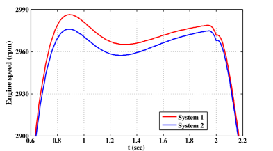
Case Study: Engine Timing Model. The Simulink demo palette presented by the Mathworks [24] contains a system representing a four-cylinder spark ignition internal combustion engine based on a model by Crossley and Cook [10]. This system is then enhanced by adding a proportional plus integral (P+I) control law. The integrator is used to adjust the steady-state throttle as the desired engine speed set-point changes, and the proportional term compensates for phase lag introduced by the integrator. In an actual implementation of such a system, such a P+I controller is implemented using a discrete-time integrator. Such integrator blocks are typically associated with a particular numerical integration technique, e.g., forward-Euler, backward-Euler, trapezoidal, etc. It is expected for different numerical techniques to produce slight variation in the results, and we wish to quantify the effect of using different numerical integrators in a closed-loop setting. We try to check if the user-provided bound of is satisfied by systems and , where is the original system provided at [24], while is a modified system that uses the backward Euler method to compute the discrete-time integral in the controller. We try to determine the input signal that leads to a violation of this bound, using a simulation-guided approach as described before. We scale the outputs in such a way that a value discrepancy of of the the output range ( ) is equivalent to a time discrepancy of seconds. These values are chosen to bias the search towards finding signals that have a small time jitter. This is an interesting scenario for this case study where the two systems are exactly equivalent except for the underlying numerical integration solver. We find the signal shown in Fig. 2, for which we find output traces with Skorokhod distance . The experiment uses simulations and the total time taken to find the counterexample is seconds.
6 Conclusion
Metrics for comparing behaviors of dynamical systems which quantify both time and value distortions have heretofore been an object of mathematical inquiry, without enough attention being paid to computational aspects and connections to logical requirements. We argue that the Skorokhod metric provides a robust definition of conformance by proving transference of a rich class of temporal logic properties. We also demonstrate the computationally tractability of the metric for practical use by constructing a conformance testing tool in a simulation and optimization guided approach for finding and quantifying non-conformant behavior of dynamical systems. Pinpointing the source of trace deviations is necessary in many engineering applications; our tool allows for independent weighing of time and value-dimension distortions in order to achieve this objective.
References
- [1] H. Abbas and G.E. Fainekos. Formal property verification in a conformance testing framework. In MEMOCODE. To Appear, 2014.
- [2] H. Abbas, B. Hoxha, G.E. Fainekos, J.V. Deshmukh, J. Kapinski, and K. Ueda. Conformance testing as falsification for cyber-physical systems. CoRR, abs/1401.5200, 2014.
- [3] M. Althoff. Reachability analysis of nonlinear systems using conservative polynomialization and non-convex sets. In HSCC 13, pages 173–182, 2013.
- [4] R. Alur and T.A. Henzinger. A really temporal logic. J. ACM, 41(1):181–204, 1994.
- [5] Brian D. O. Anderson. Optimal Control: Linear Quadratic Methods. Dover Books on Engineering. Dover Publications, 2007.
- [6] M.S. Branicky. Studies in hybrid systems: modeling, analysis, and control. PhD thesis, Massachusetts Institute of Technology, Cambridge, MA, USA, 1995.
- [7] M. Broucke. Regularity of solutions and homotopic equivalence for hybrid systems. In IEEE Conference on Decision and Control, volume 4, pages 4283–4288, Dec 1998.
- [8] P. Caspi and A. Benveniste. Toward an approximation theory for computerised control. In EMSOFT, pages 294–304. Springer, 2002.
- [9] X. Chen, E. Ábrahám, and S. Sankaranarayanan. Flow*: An analyzer for non-linear hybrid systems. In CAV 13, pages 258–263, 2013.
- [10] P.R. Crossley and J.A. Cook. A nonlinear engine model for drivetrain system development. In Control 1991. Control’91., International Conference on, pages 921–925. IET, 1991.
- [11] J.M. Davoren. Epsilon-tubes and generalized Skorokhod metrics for hybrid paths spaces. In HSCC, LNCS 5469, pages 135–149. Springer, 2009.
- [12] X. Jinand J. Deshmukh, J. Kapinski, K. Ueda, and K. Butts. Benchmarks for model transformations and conformance checking. In ARCH 14, 2014.
- [13] A. Donzé and O. Maler. Robust satisfaction of temporal logic over real-valued signals. In FORMATS, LNCS 6246, pages 92–106. Springer, 2010.
- [14] P.S. Duggirala, S. Mitra, and M. Viswanathan. Verification of annotated models from executions. In EMSOFT 13, page 26, 2013.
- [15] A. Girard, G. Pola, and P. Tabuada. Approximately bisimilar symbolic models for incrementally stable switched systems. IEEE Trans. Automat. Contr., 55(1):116–126, 2010.
- [16] E. Haghverdi, P. Tabuada, and G.J. Pappas. Bisimulation relations for dynamical, control, and hybrid systems. Theor. Comput. Sci., 342(2-3):229–261, 2005.
- [17] M. Hennessy and R. Milner. Algebraic laws for nondeterminism and concurrency. J. ACM, 32(1):137–161, 1985.
- [18] M.R. Henzinger, T.A. Henzinger, and P.W. Kopke. Computing simulations on finite and infinite graphs. In FOCS: Foundations of Computer Science, pages 453–462. IEEE Computer Society, 1995.
- [19] X. Jin, J.V. Deshmukh, J. Kapinski, K. Ueda, and K. Butts. Powertrain control verification benchmark. In HSCC 14, pages 253–262, 2014.
- [20] J. Kapinski, J.V. Deshmukh, S. Sankaranarayanan, and N. Arechiga. Simulation-guided lyapunov analysis for hybrid dynamical systems. In HSCC 14, pages 133–142. ACM, 2014.
- [21] R. Koymans. Specifying real-time properties with metric temporal logic. Real-Time Syst., 2(4):255–299, 1990.
- [22] R. Majumdar and V.S. Prabhu. Computing the Skorokhod distance between polygonal traces (full paper). CoRR, abs/1410.6075, 2014.
- [23] R. Majumdar and V.S. Prabhu. Computing the Skorokhod distance between polygonal traces. In HSCC. ACM, 2015.
- [24] The Mathworks. Engine timing model with closed loop control.
- [25] William Messner and Dawn Tilbury. Control tutorials for matlab and simulink.
- [26] R. Milner. A Calculus of Communicating Systems. LNCS 92. Springer, 1980.
- [27] D. Sangiorgi and J. Rutten. Advanced Topics in Bisimulation and Coinduction. Cambridge University Press, 2011.
- [28] P. Tabuada. Verification and Control of Hybrid Systems - A Symbolic Approach. Springer, 2009.
Appendix
A. Transference Formalism and Proofs
Example 6 (Freeze Quantification).
Suppose we want to express that whenever the event occurs, it is followed later by , and then by , such that the time difference between occurrences of and is at most , and also the time difference between occurrences of and is at most . This can be expressed in TLTL as
Thus, freeze quantification, by giving a mechanism to bind times to variables, allows us to relate, with several constraints, far apart events. ∎
Example 7 (Freeze Quantification Functions).
Suppose we want to express that whenever the event occurs, it must be followed by a response within time for some where is the time at which occurred; thus, the later occurs the more delay we can tolerate in the response time. The requirement can be expressed as . ∎
Example 8 (-relaxation for Bounded Temporal Operators – MTL).
We demonstrate how -relaxation operates on bounded time constraints through an example. Consider an MTL formula . The -relaxation of this formula over the closed interval is . This can be seen as follows. The formula can be written in TLTL syntax as:
The -relaxation of this formula according to Definition 4 is:
Thus, the time constraint interval boundaries are relaxed by . The factor of arises because there are two contributing factors: the starting time of can be “pulled back” by , and the time of can be postponed by ; thus, the time duration in between and increases by . ∎
Removing Negation using the Operator. The following identities hold relating the operator to the operator
-
1.
; and
-
2.
.
Informally, the first identity states that holds iff either (i) never holds; or (ii) there is a point where is false, and at that point and all points before it, has remained false. The second identity is similar. The first identity above allows us to “push” the negations down using the operator. The mechanism for the three interesting cases is below.
Proposition 1.
The function is a relaxation on TLTL formulae, i.e. if a timed propositional trace for a TLTL formula , then .
Proof.
Observe that, over the predicates , the function is indeed a relaxation, i.e, if for values , then also holds. The result follows by a straightforward induction argument.∎
Proof of Theorem 4.1.
Let be the formula where all freeze variable constraints are replaced by true (e.g. is ). Since , we have that there exists a retiming such that
| (3) |
This implies that both and satisfy , which can be shown by an induction argument. The interesting cases are for the and operators. We sketch the argument for the case (the argument for is similar). The time environment for assigns the time to the freeze variable where the witnessing freeze variable environment for assigns to . Let , and let be the time value which demonstrates this satisfaction (as in Definition 3), with the corresponding freeze variable environment . To show , we pick the time , with the environment for which assigns the time to the freeze variable where . It can be checked that, due to Equation 3, we have (i) , for a freeze variable in (which was previously bound); (i) ; and (ii) for all , we have . Thus, , and demonstrate that .
We now check what is the relaxation needed on the original freeze variable constraints so that satisfies the relaxed constraints. Without loss of generality, assume that each freeze variable is only quantified once in , i.e. once it is bound to a value by “”, it is not “re-bound” with another application of “”.
Let denote an assignment of time values (from ) to the freeze variables such that all the freeze variable constraints in are satisfied, i.e. is an time environment witness to the satisfaction of by . Consider a free variable assignment corresponding to , where . This is a legal variable assignment compatible with some time witnesses which demonstrate that satisfies , as shown previously. Observe that by the existence of a retiming function, for all freeze variables occurring in , we have that .
Since the time values of variables are different in and , the original freeze constraints (e.g. ) in might not be satisfied with the assignment . Consider a freeze variable constraint in . We know that is true. As for all freeze variables occurring in , by the definition of relaxation, we have that
-
1.
if ; and
-
2.
if .
This implies that is also a witness to the satisfaction of by . Thus, . ∎
Example 4 details.
Since satisfies , we must have time-stamps bound to respectively so that with these assignments, the formula is satisfied. Since is close to , for every , there is a retiming from to such that the times in are mapped to in such that (a) ; and (b) ; and (c) . Let .
The sum is
In the last step above, we use the inequality: This inequality is obtained by applying the Cauchy-Schwarz inequality to the tuples and . Thus, by Theorem 4.1, for every , we have
where . ∎
Definition 6 (-relaxation of TLTL formulae).
Let be a TLTL formula in which negations appear only on the prepositional symbols . The relaxation of (for ), denoted is defined as follows, where , a closed subset of , is the domain of the variables in ; and is a mapping from to closed intervals of such that denotes the domain of .
| is a function such that: | |||
∎
The functions define the maximal change in the value of that can occur when the input variables can vary by . The role of in the above definition is to restrict the domain of the signal variables in order to obtain the least possible bounds relaxation bounds on the signal constraints; as was done in Definition 4 for the freeze variables.
Proposition 2.
The function is a relaxation on TLTL formulae, i.e. if a timed -valued trace for a TLTL formula , then .
Proof.
The proof is similar to the proof of Proposition 1. ∎
Proof of Theorem 4.2.
The proof use the result for the propositional case, Theorem 4.1. We construct the propositions defined to be for the constraints over in the formula ; and define the TLTL formula as that obtained from by syntactically replacing each constraint in by . Let denote all such predicates for . We obtain the timed propositional traces from by mapping to propositions. By the definition of the skorokhod distance, the distance between and is less than . By Theorem 4.1, . This implies . ∎
B. Details on Case Studies
LQR-based pitch controller.
The aircraft pitch controller system has state variables, and the state vector = , where is the angle of attack, is the pitch rate, and is the pitch angle. The system has a single input (the elevator deflection angle). In deriving the control law, the designers use the state feedback law to substitute = , where is the desired pitch angle. The resulting dynamical equations of the system are of the form , and the output of the system is the state variable . Note that the matrix is the gain matrix resulting from the LQR control design technique. The values of the , and matrices are as given below:
Air-Fuel Ratio Controller.
The Air-Fuel (A/F) ratio control systems that we consider are simplified versions of industrial-scale models. Both versions have exogenous inputs, and continuous states. The inputs are engine speed (measured in rpm) and the throttle angle (in degrees). The throttle angle is a user input, and it is common to assume a series of pulses or steps as throttle angle inputs. The engine speed is considered an input to avoid modeling parts of the powertrain dynamics. In our experiments, we typically hold the engine speed constant. This is to mimic a common engine testing scenario involving a dynamometer, which is a device to provide external torque to the engine to maintain it at a constant speed. Of the continuous states, we assume that of these states are from the plant model (that encapsulates physical processes within the engine), while states belong to the controller. The plant states and denote intake manifold pressure and the A/F ratio respectively. The controller states denotes the estimated manifold pressure (with the use of an observer) used in the feed-forward control, and the state denotes the integrator state in the P+I feedback control. We check conformance with respect to the system output . For the dynamical system equations, please refer to [19, 20].