Kinect Range Sensing: Structured-Light versus Time-of-Flight Kinect
Abstract
Recently, the new Kinect One has been issued by Microsoft, providing the next generation of real-time range sensing devices based on the Time-of-Flight (ToF) principle. As the first Kinect version was using a structured light approach, one would expect various differences in the characteristics of the range data delivered by both devices.
This paper presents a detailed and in-depth comparison between both devices. In order to conduct the comparison, we propose a framework of seven different experimental setups, which is a generic basis for evaluating range cameras such as Kinect. The experiments have been designed with the goal to capture individual effects of the Kinect devices as isolatedly as possible and in a way, that they can also be adopted, in order to apply them to any other range sensing device. The overall goal of this paper is to provide a solid insight into the pros and cons of either device. Thus, scientists that are interested in using Kinect range sensing cameras in their specific application scenario can directly assess the expected, specific benefits and potential problem of either device.
keywords:
Depth Sensor, 3D , Kinect , Evaluation1 Introduction and Related Works
In the last decade, several new range sensing devices have been developed and have been made available for application development at affordable costs. In 2010, Microsoft, in cooperation with PrimeSense released a structured-light (SL) based range sensing camera, the so-called Kinect™, that delivers reliable depth images at VGA resolution at 30 Hz, coupled with an RGB-color camera at the same image resolution. Even though the camera was mainly designed for gaming, it achieved great popularity in the scientific community where researchers have developed a huge amount of innovative applications that are related to different fields such as online 3D reconstruction [25, 41, 43], medical applications and health care [15, 1], augmented reality [50], etc. Recently Microsoft released an update of their Kinect™ camera in the context of their next generation of console (XBox One) that is now based on Time-of-Flight (ToF) principle.
Both range sensing principles, SL and ToF, are quite different and are subject to a variety of error sources (see Sec. 2). This paper is meant to deeply evaluate both Kinect™cameras, denoted as Kinect and Kinect in the following, in order to extract their pros and cons which are relevant for any application incorporating this kind of device. Thus, we explicitly do not try to evaluate the devices with respect to a set of specific application scenarios, but we designed a set of seven different experimental setups as a generic basis for evaluating range cameras such as Kinect.
Several studies can be found in the literature that compare and evaluate the depth precision of both principles. However, this work is the first study comparing both versions of the Kinect cameras and offering detailed descriptions under which conditions one is superior to the other. Since Kinect™cameras are targeting the consumer market and have known sales of several millions devices, we believe that our work will be valuable for a large number of follow-up research projects.
Prior Work
A complete discussion on prior work in SL- and ToF-based range sensing would clearly go beyond the scope of this paper. Thus, we give a brief and exemplary overview on related work in the context SL- and ToF-based range sensing and focus on papers that compare different range sensing approaches and devices. In Sec. 2.3 we further refer to some key papers that deal with specific characteristics of SL and ToF range data. Additionally, we refer the reader to the surveys of Berger et al. [3] and Han et al. [17] on the Kinect as well as to the survey on Time-of-Flight cameras by Kolb et al. [28].
Kuhnert and Stommel [30] demonstrate a first integration of ToF- and stereo cameras. Beder et al. [2] evaluate and compare ToF cameras to a stereo-vision setup. Both papers emphasize that ToF and stereo data are at least partially complementary and thus an integration significantly improves the quality of range data. Furthermore, the Kinect does not use triangulation for depth calculation, and thus it does not suffer much from occlusion. As it will be shown in Sec. 4.8, the occluded area in a static scene is around 5% compared to Kinect which is around 20%. Besides Evangelidis et al. [11] has also used a ToF range camera, in comparison with Kinect, Kinect would be a better choice specifically to be utilized in depth-stereo approach. For further details on ToF-stereo fusion we refer the reader to Nair et al. [40]. In the domain of robotics, Wiedemann et al. [51] compare different ToF cameras from different manufacturers. They analyze the sensor characteristics of such systems and the application potential for mobile robots. In their work, they address several problems such as sensor calibration, automatic integration time and data filtering schemes for outliers measurements removal. Stoyanov et al. [48, 49] compare the accuracy of two ToF cameras and the Kinect camera to a precise laser range sensor (aLRF). However their evaluation methodology does not take into account the different error sources given by real-time range sensing cameras. The follow-up work by Langmann et al. [31] compares a ToF camera (pmdtec CamCube 41k) with the Kinect. Lateral resolution of depth measurements are given using a three dimensional Siemens star-like shape. The depth linearity is also compared using precise linear rail. The authors conclude that both cameras have different drawbacks and advantages and thus are meant to be used for different applications. Meister et al. [38] discuss the properties of the 3D data acquired with a Kinect camera and fused into a consistent 3D Model using the so-called KinectFusion-pipeline [41] in order to provide ground truth data for low-level image processing. The “targetbox” scene used by Meister et al. [38], also called “HCI Box”, consists of several object arranged in a m box. Nair et al. [39] discuss quality measures for good ground truth data as well as measurement and simulation approaches to generate this kind of data. We generally opted against this kind of ground truth scenery, as this approach does often not allow a proper separation of the individual error sources and, thus, it would be nearly impossible to transfer results to another application scenario.
In their book about ToF cameras Hansard et al. [18] compare between ToF cameras and the Kinect. Their comparison focuses on different material classes. They use diffuse (“class A”), specular (“class B”) and translucent (“class C”) objects or object variants for which they acquire geometric ground truth using an additional 3D scanner and applying white matte spray on each object surface. As result, they provide root mean square error (RMSE) and standard deviation (SD).
Compared to all prior work, in this paper we focus on a set of experimental setups handling an as complete as possible list of characteristic sensor effects and evaluate these effects for the Kinect and the Kinect cameras presented in Sec. 2. Before presenting the experiments and results, we discuss the fundamental problem raised by any attempt to compare these devices in Sec. 3. In Sec. 4 we present our experiments, that are all designed in such a way that individual sensor effects can be captured as isolatedly as possible and that the experiments are reproducible for other range sensing cameras.
2 Devices Principle
2.1 Structured Light Cameras - Kinect
Even though the principle of structured light (SL) range sensing is comparatively old, the launch of the Microsoft Kinect™ (Kinect) in 2010 as interaction device for the XBox 360 clearly demonstrates the maturity of the underlying principle.
Technical Foundations
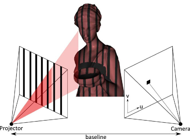
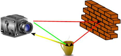
In the structured light approach is an active stereo-vision technique. A sequence of known patterns is sequentially projected onto an object, which gets deformed by geometric shape of the object. The object is then observed from a camera from a different direction. By analyzing the distortion of the observed pattern, i.e. the disparity from the original projected pattern, depth information can be extracted; see Fig. 1.
Knowing the intrinsic parameters of the camera, i.e. the focal length and additionally the baseline between the observing camera and the projector, the depth of pixel can be computed using the disparity value for this pixel as . As the disparity is usually given in pixel-units, the focal length is also converted to pixel units, i.e. , where denotes the pixel size. In most cases, the camera and the projector are only horizontally displaced, thus the disparity values are all given as horizontal distances. In this case resembles the horizontal pixel size. The depth range and the depth accuracy relate to the baseline, i.e. longer baselines allow for robust depth measurements at long distances.
There are different options to design the projection patterns for a SL range sensor. Several approaches were proposed based on the SL principle in order to estimate the disparity resulting from the deformation of the projected light patterns. In the simplest case the stripe-pattern sequence realizes a binary code which is used to decode the direction from an object point is illuminated by the beamer. Based on this principle, Hall-Holt and Rusinkiewicz [16] introduced a real-time camera based 3D system. The authors show that they could achieve full 3D reconstruction of objects using an automatic registration of different rotated range maps.
Zhang et al. [55] investigates the benefit of projection patterns composed of alternative color stripes creating color transitions that are matched with observed edges. Their matching algorithm is faster and eliminates the global smoothness assumptions from the standard SL matching algorithm. Similarly, Fechteler et al. [13] uses this color pattern to reconstruct at high-resolution human face using only two sequential patterns, which leads to a reduced computational complexity.
Additionally, Zhang and Huang [56] proposes an high resolution SL camera based on the use of color fringes pattern and phase-shifting techniques. Their system was designed to capture and reconstruct at high frame rate (up to 40Hz) dynamic deformable objects such as human face.
SL cameras, such as the Kinect, use a low number of patterns, maybe only one, to obtain a depth estimation of the scenery at a “high” frame rate ( FPS). Typically, it is composed of an near infra-red (NIR) laser projector combined with a monochrome CMOS camera which captures depth variations of object surfaces in the scene.
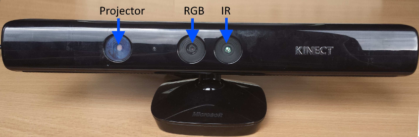
The Kinect camera is based on the standard structured light principle where the device is composed of two cameras, i.e. a color RGB and a monochrome NIR camera, and an NIR projector including a laser diode at nm wavelength. The baseline between the NIR projector and the NIR camera is cm see Fig. 2. The NIR projector uses a known and fixed dot pattern to illuminate the scenery.
Simple triangulation techniques are later on used to compute the depth information between the projected pattern seen by the NIR camera and the input pattern stored on the unit. For each pixel , depth is estimated by finding the best correlation pattern patch, typically in a pixel window, on the NIR image with the corresponding projection pattern. The disparity value is given by this best match. Note that the Kinect device performs internally an interpolation of the best match operation in order to achieve sub-pixel accuracy of pixel. A detailed description of the Kinect disparity map computation can be found at the ROS.org community website [29], where the Kinect’s disparity map computation has been reverse engineered and a complete calibration procedure is deduced.
2.2 Time-of-Flight (ToF) Cameras
The ToF technology is based on measuring the time that light emitted by an illumination unit requires to travel to an object and back to the sensor array [32]. In the last decade, this principle has found realization in microelectronic devices, i.e. chips, resulting in new range-sensing devices, the so-called ToF cameras. Here, we will explain the basic principle of operation of ToF-cameras. It should be noted that for the specific device of the new Kinect camera, issued by Microsoft Corp. in conjunction with the XBox 360 game console, only little technical detail is known.
The Kinect utilizes the Continuous Wave (CW) Intensity Modulation approach, which is most commonly used in ToF cameras. The general idea is to actively illuminate the scene under observation using near infrared (NIR) intensity-modulated, periodic light (see Figure 3). Due to the distance between the camera and the object (sensor and illumination are assumed to be at the same location), and the finite speed of light , a time shift is caused in the optical signal which is equivalent to a phase shift in the periodic signal. This shift is detected in each sensor pixel by a so-called mixing process. The time shift can be easily transformed into the sensor-object distance as the light has to travel the distance twice, i.e. .
From the technical perspective, the generator signal driving the illumination unit results in the intensity modulated signal which, after being reflected by the scene, results in an incident optical signal on each sensor pixel. Note, that the optical signal may be deformed by nonlinear effects e.g. in the LEDs of the illumination unit. The incident signal is correlated with the reference generator signal . This mixing approach yields the correlation function which is sampled in each pixel
The phase shift is computed using several correlation measurements with varying illumination and reference signals and , respectively, using some kind of demodulation function, i.e.
Frequently, is called phase image or correlation image. We will use the latter notation in order to prevent confusion with the phase shift ( distance). Practically, the correlation images are acquired sequentially, however there is the theoretic option to acquire all correlation images in parallel, e.g. by having different phase shifts for neighboring pixels. Note, that due to the periodicity of the reference signal, any ToF-camera has a unique unambiguous measurement range.
The first ToF cameras like the prototypes from pmdtechnolgies [53] used sinusoidal signals with a constant modulation frequency and a reference signal equal to with an additional phase offset , i.e. . For this approach, usually four correlation images for are acquired leading to a distance value of
where is the angle between the positive x-axis and the point given by the coordinates .
The Kinect camera applies this CW intensity modulation approach [52]. Blake et al. [5] reverse engineered the Kinect-driver. This revealed, that the Kinect acquires correlation images, from which nine correlation images are used for a three-phase reconstruction approach based on phase shifts of and at three different frequencies. Using multiple modulation frequencies the measurement range can be exceeded [9] Although the Kinect camera can obtain depth values for distances longer than 9 meters, the official driver masks the distances further than around 4.5 meters.
The purpose of the tenth correlation image is still not clear. Even though the technical specifics of the Kinect have not been explicitly revealed by Microsoft, it definitely applies the basic principle of correlation as described above. The illumination unit consists of a laser diode at nm wavelength.
In Sec. 3 we discuss further technical details regarding the Kinect driver.
2.3 Error Sources for Kinect and Kinect
SL and ToF cameras are active imaging systems that use standard optics to focus the reflected light onto the chip area. Therefore, the typical optical effects like shifted optical centers and lateral distortion need to be corrected, which can be done using classical intrinsic camera calibration techniques. Beyond this camera specific calibration issues, SL and ToF cameras possess several specific error sources, which are discussed in the following and which also apply to Kinect and/or Kinect. As a detailed discussion of prior work in relation to these error sources would go beyond the scope of this paper, we only give some relevant links to prior work that relates to the individual effects for either system.
Ambient Background Light [SL, ToF]: As any other camera, ToF and SL cameras can suffer from ambient background light, as it can either lead to over-saturation in case of too long exposure times in relation to the objects’ distance and/or reflectivity, e.g. causing problems to SL-systems in detecting the light pattern. Both, the Kinect and the Kinect are utilized with a band-pass filter, suppressing background light out of the range of the illumination. Kinect provides a suppression of background intensity on the chip.
For ToF cameras specific circuitry has been developed, e.g. the Suppression of Background Intensity approach for PMD cameras [44] that electronically filter out the DC-part of the light. For SL systems outdoor application is usually hard to achieve, which has also been stated for the Kinect [10].
Multi-Device Interference [SL, ToF]: Similar to any other active sensing approach, the parallel use of several Kinect cameras may lead to interference problems, i.e. the active illumination of one camera influences the result of another camera.
For Kinect the potential interference problem given by multiple NIR patterns projected into the scene is very difficult to solve. Butler et al. [7] propose a “Shake‘n’Sense” setup where one (or each) Kinect-device is continuously shaken using an imbalanced rotating motor. Thus, the projected pattern performs a high frequency motion that appears significantly blurred for another device. An alternative approach is introduced by Berger et al. [4]. They add steerable hardware shutters to the Kinect-devices’ illumination units resulting in a time-multiplex approach. For ToF cameras the signal shape can be altered in order to prevent multi-device interference, e.g. for sinusoidal signal shapes different modulation frequencies can simply be used to decouple the devices [27].
Temperature Drift [SL, ToF]: A common effect to many technical devices is the drift of the system output, i.e. the distance values in the case of Kinect cameras, during the device warm-up. The major difference between the SL and the ToF approach is that an SL camera usually does not produce as much heat as a ToF camera. This is due to the fact, that the required illumination power to cover the full scene width and depth in order to get a sufficient signal-to-noise (SNR) for the optical signal for a ToF camera is beyond the power needed to generate the relatively sparse point-based pattern applied by the Kinect. As a consequence, the Kinect can be cooled passively whereas the Kinect requires active cooling.
For the Kinect significant temperature drift has been reported by Fiedler and Müller [14]. Early ToF-camera studies e.g. from Kahlmann et al. [24] of the Swissranger™ camera exhibit the clear impact of this warm-up on the range measurement. More recently smaller ToF cameras for close range applications such as the camboard-nano series provided my pmdtechnolgies do not require active cooling, however, no temperature drift investigations have been reported so far.
Systematic Distance Error [SL, ToF]: Both Kinect cameras suffer from systematic error in their depth measurement. For the Kinect the error is mainly due to inadequate calibration and restricted pixel resolution for estimation of the point locations in the image plane, leading to imprecise pixel coordinates of the reflected points of the light pattern [26]. Further range deviations for the Kinect result from the comparably coarse quantization of the depth values which increases for further distances from the camera. For Kinect, on the other hand, the distance calculation based on the mixing of different optical signals with reference signals requires either an approximation to the assumed, e.g. a sinusoidal signal shape or an approximation to the phase demodulation function . Both approximations lead to a systematic error in the depth measurement. In case of an approximated sinusoidal shape this effect is also called “wiggling” (see Figure 4, top left). The systematic error may depend on other factors, such as the exposure time.
For Kinect Khoshelham and Elberink [26] present a detailed analysis of its accuracy and depth resolution. They conclude that the systematic error is below some cm, however it increases on the periphery of the range image and for increasing object-camera distance. Smisek et al. [47] present a geometric method to calibrate the systematic error of the Kinect. Herreta et al. [19] proposed a joint calibration approach for the color and the depth camera of the Kinect. Correction schemes applied to reduce the systematic error of ToF cameras with sinusoidal reference signals simply model the depth deviation using a look-up-table [23] or function fitting, e.g. using b-splines [33].
Depth Inhomogeneity [SL, ToF] At object boundaries, a pixel may observe inhomogeneous depth values. Due to the structured light principle, occlusion may happen at object boundaries where parts of the scene are not illuminated by the infra-red beam which results in a lack of depth information in those regions (invalid pixels). For ToF cameras, the mixing process results in a superimposed signal caused by light reflected from different depths, so-called mixed pixels. In the context of ToF cameras these pixels are sometimes called flying pixels. The mixed, or flying signal leads to wrong distance values; see Figure 4, top right.
There are simple methods relying on geometric models that give good results in identifying flying pixel, e.g. by estimating the depth variance which is extremely high for flying pixel [45]. Denoising techniques, such as a median filter, can be used to correct some of the flying pixels.
Note that flying pixels are directly related to a more general problem, i.e. the multi-path problem; see below.
Multi-Path Effects [SL, ToF] Multi-path effects relate to an error source common to active measurement systems: The active light may not only travel the direct path from the illumination unit via the object’s surface to the detector, but may additionally travel indirect paths, i.e. being scattered by highly reflective objects in the scene or within the lens systems or the housing of the camera itself, see Fig. 4 bottom left. In the context of computer graphics this effect is known as global illumination. For ToF cameras these multiple responses of the active light are superimposed in each pixel leading to an altered signal not resembling the directly reflected signal and thus a wrong distance. For Kinect indirect illumination mainly causes problems for highly reflecting surfaces, as dots of the pattern may be projected at other objects in the scene. However, objects with a flat angle to the camera will lead to a complete lack of depth information (see also Sec. 4.7).
For ToF cameras several correction schemes for multi-path effects have been proposed for sinusoidal signal shapes. Falie and Buzuloiu [12] assume that the indirect effects are of rather low spatial frequency and analyze the pixel’s neighborhood to detect the low-frequency indirect component. Dorrington et al. [8] present an analytic formulation for the signal superposition resulting in a non-linear optimization scheme per pixel using different modulation frequencies.
Intensity-Related Distance Error [ToF] Considering a highly reflecting object and a second object with the same distance to the camera but with low reflectivity in the relevant NIR range, a reduced SNR is expected. Beyond this, it has frequently been reported that ToF cameras have a non-zero biased distance offset for objects with low NIR reflectivity (see Figure 4, bottom right).
Lindner et al. [35] tackle the specific intensity-related error using phenomenological approaches. In general, there are at least two possible explanations for this intensity-related effect. The first assumption explains this effect is a specific variant of a multi-path effect, the second one puts this effect down to the non-linear pixel response for low amounts of incident intensity.
Semitransparent and Scattering Media [SL, ToF] As for most active measuring devices, media that does not perfectly reflect the incident light potentially causes errors for ToF and SL cameras. In case of ToF cameras, light scattered within semitransparent media usually leads to an additional phase delay due to a reduced speed of light.
The investigations done by Hansard et al. [18] give a nice overview for specular and translucent, i.e. semitransparent and scattering media for ToF cameras with sinusoidal reference signal and the Kinect. Kadambi et al. [22] show that their coding method (originally designed to solve multi-path errors for ToF cameras) is able to recover depth of near-transparent objects using their resulting time-profile (transient imaging). Finally, a detailed state-of-the-art report is given by Ihrke et al. [21] where different methods are described in order to robustly acquire and reconstruct such challenging media.
Dynamic Scenery [SL, ToF] One key assumption for any camera-based system is that each pixel observes a single object point during the whole acquisition process. This assumption is violated in case of moving objects or moving cameras, resulting in motion artifacts. In real scenes, motion may alter the true depth. Even though Kinect acquires depth using only a single NIR image of the projected pattern, a moving object and/or camera leads to improper detection of the pattern in the affected region. ToF cameras as the Kinect require several correlation images per depth image. Furthermore, their correlation measurements get affected by a change of reflectivity observed by a pixel during the acquisition. Processing the acquired correlation images ignoring the motion present during acquisition leads to erroneous distance values at object boundaries (see Figure 4, top right).
However, no real investigations have been done yet for the Kinect to study the effect of motion blur on the depth measurement quality. Nevertheless the work of Butler et al. [7] uses the motion blur property to solve the problem of multiple Kinect devices interference.
For ToF cameras several motion compensation schemes have been proposed. Schmidt and Jähne [46] detect motion artifacts using temporal gradients of the correlation images , i.e. a large gradient in one of the correlation images indicates motion. This approach also performs a correction using extrapolated information from prior frames; see also discussion in Hansard et al. [18], Sec. 1.3.3. Since motion artifacts result from in-plane motion between subsequent correction images, several approaches use optical flow methods in order to re-align the individual correlation images. Lindner and Kolb [34] apply a fast optical flow algorithm [54] three times in order to align the four correlation images to the first correlation image . As optical flow algorithms are computationally very expensive, these approaches significantly reduce the frame rates for real-time processing. A faster approach is motion detection and correction using block-matching techniques applied pixels where motion has been detected [20].
| Mean | SD | RMSE (plane fit) | |
|---|---|---|---|
|
Kinect Offic. |
|||
|
Kinect Post |
|||
|
Kinect Offic. |
|||
|
Kinect Open |
|||
|
Kinect Raw |
 |
 |
 |
 |
| Kinect Offic. | Kinect Post | ||
 |
 |
 |
 |
| Kinect Offic. | Kinect Open | ||
 |
 |
||
| Kinect Raw | |||
3 General Considerations for Comparing Kinect and Kinect
Before presenting the experimental setups and the comparison between the two Kinect devices, we have to consider the limitations which this kind of comparison encounters. For both, the Kinect and the Kinect camera, there are no official, publicly available reference implementations which explain all stages from raw data acquisition to the final range data delivery. Thus, any effect observed may either relate to the sensor hardware, i.e. to the measurement principle as such, or to the algorithms applied to raw data or, in a post-processing manner, to the range data which are integrated in the camera systems.
Anticipating the further discussion in this section, we explicitly opted to work with both Kinect cameras in a “black box” manner using the official drivers, as it is impossible to achieve “fair conditions” for the comparison, i.e. a comparison which neutralizes the effects from diverse filters applied in range data processing. This is mainly due to the fact, that data processing is applied on the level of raw data, i.e. disparity maps or correction images, as well as on the level of range data; see detailed discussion below. Attempts to reverse engineer the processing functionality usually do not lead to the same data quality; see below. Thus, taking the devices as they are, including the official, closed-source drivers, is the most appropriate approach from the perspective in utilizing them for any kind of application.
However, the disparity map from the Kinect is different from common representation, i.e. disparity value does not refer to an infinite distance. According to the reverse engineered disparity map computation from ROS.org, the disparity map is normalized and quantized between and (using 11 bits storage), that requires a more complex mapping function in order to convert disparity into depth values. Note, that the quantization of the disparity map leads to quantization of range values, which in some cases negatively influences the statistical analysis or, in some cases, make it completely useless. For example, it is impossible to derive a per-pixel noise model for the Kinect taking only individual pixel distance measurements of a static scene; see Sec. 4.1 and Nguyen et al. [42].
Different alternatives have been proposed for depth value estimation for Kinect disparity maps [26]. In general, it is possible to access the raw data of the Kinect camera, i.e. infrared image of the scene with the dots pattern, but it would go far beyond the scope of this paper to provide further insight into the Kinect’s method of operation by reverse engineering. On the other hand, solely post-processing the delivered range data hardly improves the quality; see below.
As described in Sec. 2.2. the Kinect camera applies the CW approach. Additionally, the reverse engineered OpenKinect driver [5] gives insight into some details of data processing applied in the Kinectİn a first processing stage, the correction images are converted to intermediate images. At this stage a bilateral filter is applied. In a second stage, the final range data is computed out of the intermediate images, joining the three different range values retrieved from the three frequencies. At this level, an outlier (or flying pixel) removal is applied. The OpenKinect driver allows to deactivate the two filters, thus the delivered range data can be considered as being based raw correction images.
The described functionality allows data access on several levels, i.e.
-
•
Kinect Offic and Kinect Offic: Range data as delivered by the official driver provided by Microsoft for the Kinect111Kinect For Windows SDK and for the Kinect using the Developer Preview driver222Kinect For Windows SDK (JuneSDK).
-
•
Kinect Post: Additional post-processing using filtering; here we use a bilateral filter. Note, that the filter has to operate on data with already masked out, i.e. invalid pixels.
-
•
Kinect Open: The reengineered data processing of the OpenKinect driver by Blake et al. [5].
-
•
Kinect Raw: The reengineered data processing of the OpenKinect driver by Blake et al. [5] with deactivated filtering, i.e. range data directly computed from the raw data.
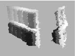
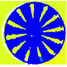
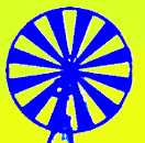
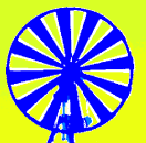
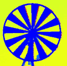
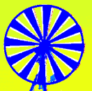
We apply these five different options to a simple static scene, where the cameras observe a planar wall, analyzing the statistics for frames; see Fig. 5 and Sec. 4.8). For this scenario, the data is comparable among different drivers of a device, as the cameras have not been moved while switching to a different driver. However, the data is not fully comparable between Kinect and Kinect. Additionally, we used a dynamic scenery with a rotating Siemens star; see Fig. 6 and Sec. 4.8).
The results for the static wall and the Siemens star are presented in Figs. 5 and 6, respectively. The results can be summarized as follows:
-
•
Post-processing the Kinect-data does not improve the quality, as the problematic regions of the range image are already masked out; see Fig. 6, top row. The quality of the Kinect device is mainly driven by strong depth quantization artifacts, which get apparent in the standard deviation; see Fig. 5, middle column, first two rows.
- •
-
•
Disabling the internal filters for the Kinect mainly shows negative effects for the rotating Siemens star; see Fig. 6. The filtering of the correction images and the flying pixel removal clearly removes the artifacts at the jumping edges of the Siemens star.
4 Experimental Results And Comparison
| Test-ScenariosEffect |
Amb. Backgr. Light |
Multi-Device Interf. |
Temperature Drift |
Systematic Error |
Depth Inhomogeneity |
Multipath Effect |
Intens.-Rel. Error |
Semitrans. & Scatter. |
Dynamic Scenery |
| Ambient Background Light | |||||||||
| Multi-Device Interference | |||||||||
| Device Warm-Up | |||||||||
| Rail Depth Tracking | |||||||||
| Semitransparent Liquid | |||||||||
| Reflective Board | |||||||||
| Turning Siemens star |
In section 4.2–4.8 we present the different test scenarios we designed in order to capture specific error sources of the Kinect and the Kinect-cameras. Before going into the scenarios, in Sec. 4.1 we will briefly present the camera parameters and the pixel statistics.
Our major design goal for the test scenarios was to capture individual effects as isolatedly as possible. Furthermore, we designed the scenarios in a way, that they can be reproduced in order to adopt them to any other range sensing system that works in a similar depth range. Tab. 1 gives an overview of the different test scenarios and the effects they address; see also Sec. 2.3. We focus on the range of mm to mm333Microsoft Developer network, Kinect sensor as we operate the Kinect in the so-called near-range-mode, which is optimized for this depth range. Also it covers the depth range supported by Kinect which is mm to mm444Kinect for windows, features.
For all tests we utilize a Kinect (Kinect for Windows v1 sensor with activated near mode) and a Kinect (Microsoft camera prototype available from the Developer Preview Program). Data access for the Kinect is done via the official driver provided by Microsoft555Kinect For Windows SDK and for the Kinect using the Developer Preview driver666Kinect For Windows SDK (JuneSDK). All data evaluations have been done using Matlab.
The major quantitative results for the comprehensive comparison are summarized in Tab. 4 indicating the major differences, strengths and limitations of both systems.
At this point, we want to refer to the discussion in Sec. 3 state explicitly, that both Kinect cameras are used in a “black box” manner. Thus, even though we refer to characteristics of the specific range measurement techniques, the resulting effects may not only relate to the sensor hardware, i.e. to the measurement principle as such, but also to the post-processing integrated into the cameras
4.1 Camera Parameters and Noise Statistics
| Parameter | Kinect | Kinect |
|---|---|---|
| Resolution | 640480 | 512424 |
| Focal Length [px] | (583.46, 583.46) | (370.79, 370.20) |
| Center [px] | (318.58, 251.55) | (263.35, 202.61) |
| Dist. (; ; ; ; ) | -0.07377, 0.1641, 0, 0, 0 | 0.09497, -0.2426, 0, |
| 0.00076, -0.00017 |
| Pixel | Gaussian () | Poisson () | ||
|---|---|---|---|---|
| Center | [1023.91, 4.42] | 0.0025 | [17.47, 1007.47] | 0.0024 |
| Intermed. | [1074.77, 3.77] | 0.0017 | [14.10, 1061.40] | 0.0017 |
| Corner | [1127.21, 24.03] | 0.0019 | [101.73, 1030.02] | 0.0019 |
| Center Pixel | Intermed. Pixel | Corner Pixel |
|---|---|---|
As most applications require full 3D information, we first estimate the intrinsic parameters for both devices using standard calibration techniques based on a planar checkerboard from the OpenCV library [6]; see Tab. 2. For both devices, images of the checkerboard were acquired with different orientations and distances. For the Kinect, we directly use the amplitude image delivered by the camera. Whereas for the Kinect, we use the NIR image of the depth sensor. Since the dot pattern of the Kinect may degrade the checkerboard detection quality in the NIR image, we block the laser illumination and illuminate the checkerboard with an ambient illumination.
Furthermore, we want to analyze the noise statistics for the Kinect and the Kinect. As already stated in Sec. 3, the strong quantization applied in the Kinect makes it hard to derive per-pixel temporal statistic values. In the literature there are alternative approaches using a mixed spatiotemporal analysis to derive some kind of noise statistics [42], but this approach is difficult to compare with pure temporal statistics. Therefore, we focus on the Kinect’s temporal statistics only.
For the temporal statistics we acquired frames of the Kinect observing a planar wall at about 1 meter distance. The OpenKinect driver with deactivated filtering was used to obtain unchanged range data. Fig. 7 shows the histograms for a central, an intermediate and a corner pixel of this time series including fits for a Gaussian and a Poisson distribution. Both fits were done using MATLAB. We use non linear least square optimization approaches in order to get the suitable parameters for the Poisson distribution. Tab. 3 gives the resulting parameters of both fitting for the three pixel statistics as well as the corresponding RMSE. It can be noted that corner pixels have a higher variance than pixel at the center area of the image, which is due to a reduced amplitude of the illumination in corner regions. We can also deduce that the Poisson distribution and the Gaussian fitting results in the same fitting quality.
4.2 Ambient Background Light
Goal
This test scenario addresses the influence of ambient light onto the range measurement of the Kinect and the Kinect cameras. The primary goal for the experiment is to show the relation between ambient background radiance incident to the Kinect and the delivered depth range of the sensor. The main focus for this experiment is thus to measure the incident background radiance with respect to image regions accurately.
As both Kinect cameras do have imperfect illumination in the sense, that pixels in the vicinity on the image receive less active light than pixels close to the center, a secondary goal is to given some insight into a possible spatial variation of the influence of ambient background light.
Experimental Setup
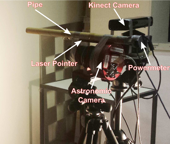
The Kinect camera is mounted mm in front of a approximately diffuse white wall in an environment where the amount of light can be controlled using three HALOLINE ECO OSRAM W halogen lamps. The radiosity on the wall depends on the number of active lamps and their distance to the wall. We measure the radiant emittance of the surface resulting from our light sources with a Newport 818-SL powermeter. The powermeter directly delivers power intensity in W/cm2 and it is calibrated to nm, which relates to the Kinect’s laser diode illumination of nm. An additional laser pointer allows for the directional adjustment of the powermeter’s pipe to a point on the wall in order to accurately measure the radiance. To register the point at the wall with a pixel in the Kinect camera, we temporally attached a small cuboid as depth marker to the wall.
As both Kinect cameras have an NIR-filter suppressing visible light777We did not explicitly measure the NIR filter, as this would require to destroy the Kinect camera., we equip the powermeter with an additional Kodak Wratten high-pass filter number 87C. This filter has a % cutoff at nm. A pipe is mounted to the powermeter in order to measure the incident radiance for a specific spatial direction from single point on the wall.
We further add an Atik 4000 astronomy photography camera equipped with the same NIR filter alongside with a powermeter in order to verify radiance measurements provided by the powermeter setup. The astronomy camera measures the radiant emittance in a linear relation to the number of photons received per pixel, i.e. per observed direction. In our experiments we found a proper linear relation between both measurements.
We interrelate the radiance measurement of the powermeter to daylight condition. Therefore, we acquired a radiant flux density reference measurement with the powermeter setup without pipe of direct sunlight on a sunny summer day in central Europe. This results in mW/cm2. Furthermore, we relate the radiant flux density measurement to the incident radiance measurement of an indirectly illuminated diffuse white paper using the powermeter with pipe at m distance resulting in a factor of . As the later setup is comparable to the evaluation setup for the Kinect cameras, we can deduce a sun reference incident radiance value of about W/cm2.
The final radiance measurements are done with the powermeter setup. The radiance measurements take place when the Kinect camera is turned off in order to prevent interference with the camera’s illumination unit. We acquired frames for various light conditions up to W/cm2. Since we expect some variation of the effect for different pixel locations, we measured three points along the half diagonal, i.e. a point close to the upper left corner, the principle point of the range image and one intermediate point in between both points.
Evaluation and Results
We apply a variance analysis for the frames of range values delivered by each camera for each of the pixels (center, intermediate, corner) by computing the Standard Deviation (SD) over time
| (1) |
and plot this as function over the ambient light intensity; see Fig. 9, top. Additionally, Fig. 9, bottom, shows explicit distance values including box plots as function over ambient light.
It can be observed, that the Kinect is not able to handle background light beyond W, whereas the Kinect delivers range data throughout the full range of ambient light applied in the experiment.
The Kinect delivers more robust depth values than the Kinect throughout the ambient background light range where valid data is delivered. All observed pixels are below mm SD and the max. variation from the median is mm for the corner pixel. The SD and the box plots show, that for the Kinect the depth variation is hardly effected by the ambient light, as long as valid range data is delivered. The plots for the different pixels show, that the variation increases for pixels closer to the image vicinity.
The Kinect, at the other hand, shows the expected raise in the depth variation for increasing ambient light due to a reduced SNR. Whereas the center and the intermediate pixel show similar SD below W as the Kinect, i.e. below mm, the box plots reveal a larger number of outliers compared to the Kinect. However, the Kinect’s corner pixel delivers worse SD and quantile statistics than the one for the Kinect. In the range beyond W ambient light, the variation increases to some and mm for the center, intermediate and corner pixel, respectively. The effect that the center pixel gets worse than the intermediate pixel may be explained by oversaturation effects solely due to the active illumination of the Kinect.
4.3 Multi-Device Interference
Goal
This experiment addresses the problem arising from the interference of the active illumination between several Kinect-cameras of the same type, when running them in parallel. Primarily, we want to evaluate the influence of the interference on the range measurement. Secondarily, we want to gain some insight into the temporal and spatial distribution of the artifacts.
Note, that in contrast to other ToF-cameras (see Sec. 2.3) we are not able to modify the modulation frequencies for the Kinect in order to reduce or suppress multi-device interference artifacts.
Experimental Setup
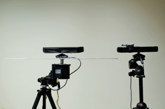
The general idea of the experiment is to acquire an approximately diffuse white planar wall, adding a second Kinect device of the same kind as interference over a longer period of time. As the Kinect uses a static structured light pattern, a fully static setup may not capture the overall interference. As circumventing interference for the Kinect may not always be possible with a “Shake’n’Sense”-like approach [7], we investigate the influence of the camera poses of the two devices on the interference. Thus, for the Kinect setup, we mount the interfering device on a turntable and rotate it about the vertical axis with RPM in order to get a variation of the overlay of the SL-patterns of the two devices. The angular speed is low enough to prevent any motion artifacts. We also investigated different inter-device distances, but the resulting impact on the interference was comparable. The Kinect setup the interfering device is always static. The distance between the wall and the Kinect was set to m and the distance between the devices is m; see Fig. 10. We do not take the exact orientation of the measuring and the interference devices into account, the measuring and the interfering device, but both devices observe approximately the same region on the wall.


Evaluation and Results
In order to account for a potential misalignment of the Kinect towards the wall, we use a RANSAC plane fit to the range data with inactive interference device. The per-pixel ranges values, deduced from this plane fit, are considered as reference distances . We compute the deviation for each frame in respect to the reference distance as Root-Mean-Square Error (RMSE), i.e.
| (2) |
where represent the width and height of the averaged range image, respectively.
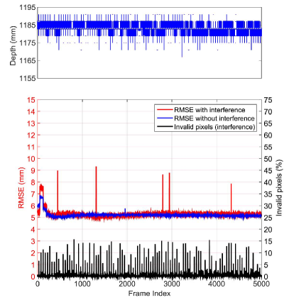
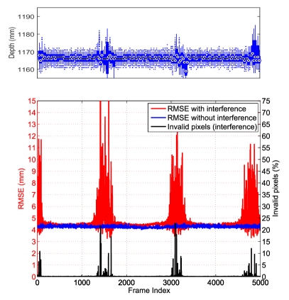
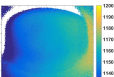
As can be seen in Fig. 11, the active frequency pattern of the Kinect has a stronger interference than the structured light pattern for the Kinect for most poses of the interfering camera. On average, the Kinect shows little interference effect (RMSE mm), beside some very prominent poses (RMSE up to mm). Fig. 12, mid-right, shows a sample range image with a high RMSE. The Kinect camera shows low interference for the majority of the frames (RMSE: mm), but extreme interference errors for some % of the frames (RMSE up to mm) that occur in a sequence which has a nearly constant repetition rate. This behavior is most likely due to the asynchronous operation of the two devices. A signal drift over time between the signals generated in both devices would lead to a repetitive interference pattern as the one observed. The range statistics represented in Fig. 11, top, shows that the median in Kinect is not altered by interference, which is mainly due to the strong quantization applied in the disparity maps. In phases of maximum interference, the Kinect delivers increased drift of the median, up to mm, and a stronger variation.
Regarding the invalid pixels, the Kinect nearly always delivers invalid pixels. For the initial pose, we find some % invalid pixels; see Fig. 12, left. While changing the pose of the interfering device, we find up to % invalid pixels; see Fig. 12, mid-left. The Kinect does not deliver invalid pixels in the non-interfered periods, but in the interference periods up to % of invalid pixels have been observed; see Fig. 12, right.
We want to point out that we always observe strong variations within the first frames, i.e. the first seconds after starting the acquisition with the Kinect. In this experiment we have an increased RMSE of up to mm without interference and mm with interference. Therefore, it is advisable to not use this initial sequence captured with the Kinect.
4.4 Device Warm-Up
Goal
This test scenario is designed to evaluate the drift in range values during the warm-up in standard operation, i.e. the stability of the range measurements of both Kinects with respect to the operating time.
Experimental Setup
We accommodate the device in a room with a constant temperature of C which is actively controlled by an air conditioning system with a variance below C. We start to operate the device measuring a planar wall at a distance of mm. We acquire frames in a row and drop frames for s ( frames) afterwards and repeat this until a total time of minutes. During the acquisition a digital thermometer (precision C) records the temperature inside the Kinect devices. The temperature in the device interior is measured with a flexible sensor tip inserted through the ventilation holes. Thus, the devices remained intact in order to keep the original temperature dissipation system.
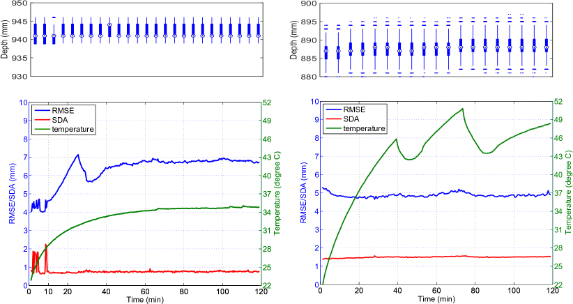
Evaluation and Results
As the variation in the range data is smaller for the cold device than for the warm device, we make a RANSAC fit to the averaged first steady sequence of frames, resulting in a reference depth image . However, for Kinectthe first steady sequence of 200 frames was captured after minutes, as we observe a very strong variation in this initial range of measurements. Nevertheless, since the RANSAC is applied to the whole frame there might be some bias to the reference frame. We calculate the RMSE for the average of all frames in a frame sequence with respect to the fitted plane as
| (3) |
Furthermore, we calculate the per-pixel standard deviation average (SDA) for each sequence of frames .
| (4) |
The results for the device warm-up test are shown in Fig. 13. The fluctuation in the temperature of the Kinect is due to the cooling system, that gets activated and deactivated depending on the system temperature. For the Kinect there is only a small temperature difference of 11∘C after 120 minutes. The results show that Kinect has in general less error than the Kinect and SDA and RMSE are nearly constant over time. The Kinect has strong error and variation fluctuations in the first min of the warm-up phase. After the device has reached its operation temperature, the distance SDA stays within mm, which is slightly better than for the Kinect which has a distance SDA of mm. However, the distance error is higher for the Kinect (RMSE mm) than for the Kinect (RMSE mm). The distance box plots in Fig. 13, top, show less variation for the Kinect than for the Kinect. However, we again point out, that the homogeneous appearance of the box-plots for the Kinect partially result from the heavy quantization applied in this device.
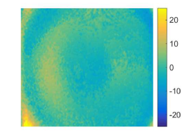
Fig. 14 shows the depth error in respect to the fitted plane in absolute signed values. The depth images are taken at minute 60, when both devices are at a stable temperature. As it can be seen in the depth images the Kinect delivers smoother results with less out of plane errors compared to Kinect, which is consistent with the RMSE values at minute 60.
4.5 Rail Depth Tracking
Goal
This test scenario primarily addresses the quality of the range data in respect with ground truth distances for a planar wall. The test involves the linearity including planarity tests as well as the intensity related error. The latter applies only for the Kinect camera. A secondary goal is to give some clue about the dependence of the error from the pixel location, therefore we evaluate the error at a few different image locations.
Experimental Setup
The setup comprises a motorized linear rail mounted perpendicular to a white wall, which measures distances between m and m at a step-size of cm. The camera is mounted on the carriage of the rail facing perpendicular to the wall. As the wall does not cover the full range image for farther distances, we evaluate planarity and linearity of the camera only within a region-of-interest including pixels lying on the white flat wall in the full distance range. The pixel region of interest for Kinect is (1,1), (630,480) and (74,4), (502,416) for Kinect. Furthermore, we observe some pixels along a line-of-interest from the image center to the top-left corner, which are always covering the wall. We acquire frames for each distance. For the evaluation of the intensity-related error, the acquisition is repeated with a checkerboard attached to the wall. The checkerboard consists of gray-level rectangles on white background, where the gray-level degrades from % to % black. The checkerboard has been printed using a standard laser printer which delivers sufficiently proportional reflectivity in the visual and the NIR range.
In order to re-project the range values into 3D-space, we first estimated the camera intrinsics using the well known photometric calibration technique from [57]. Similar approaches have been applied to the Kinect [37] (where the laser beam is obstructed and an incandescent lamp is used to highlight the checkerboard in order to acquire a reliable NIR image of the calibration rig) and for ToF-cameras [33].
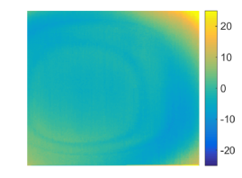
4.5.1 Linearity – Evaluation and Results
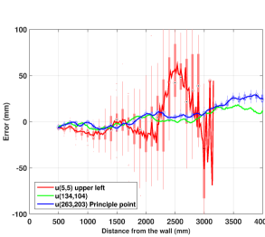
The evaluation of the linearity requires a proper measurement of the ground truth distances for the range images acquired with the rail system. As a perfect orthogonal alignment of the camera towards the wall can not be guaranteed, we propose to bypass this problem using photometric methods. Having a complete lens calibration of both camera systems (i.e. depth and color intrinsic and distortion parameters) and the extrinsic transformation between the High-Res color camera and the depth camera, the precise 3D camera position of the depth camera can be obtained using a simple black-white checkerboard reference fixed to the planar wall and which we acquire at different rail positions. The corresponding 3D positions of the depth camera relative to the reference wall is done using the standard method [57]. A 3D line was fitted to these 3D positions using a RANSAC statistical approach which gives the robust orientation of the linear rail. Finally, knowing the precise displacement of each measurement of the linear rail (we use a cm step size), the 3D position of the camera can robustly be estimated and thus a precise ground-truth of the wall be generated using the lens parameters of the depth camera. Having the ground truth distance for a given camera-to-wall distance for each pixel, we calculate the signed error (SE) for the average of all depth measurements at the rail system, thus suppressing sensor noise
| (5) |
within the region-of-interest consisting of pixel. For some pixels along the line-of-interest we also evaluate the individually signed linearity errors.
Furthermore we calculate the variance for each pixel in the region-of-interest using the frames taken for each camera-to-wall distance in order to retrieve the standard deviation average SDA according to Eq. 4.
Fig. 15, top, shows the signed linearity errors for both Kinects for the selected pixels with some box plots superimposed. As can be seen in Fig. 15 right, the Kinect delivers more precise range data than the Kinect, if the corner pixel is not taken into account. In the proposed work range of the Kinect below m the error lies in the range of mm for the best (central) pixel and of mm for the worst (peripheral) pixel. The SD for the Kinect below m is very similar for all pixels and is below mm. Above m the distance error of the Kinect strongly increases for peripheral pixels. Even though there seem to be some fluctuations in the distance error for the Kinect, this effect is much smaller and much less regular than the “wiggling”-error observed so far for ToF-cameras [33, 35]. For pixels not in the extreme periphery the absolute per-pixel distance error and the SD lies in the range of mm and mm, respectively. For the corner pixel the SD range increases to mm.
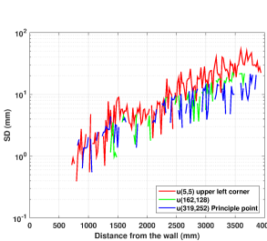
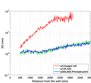
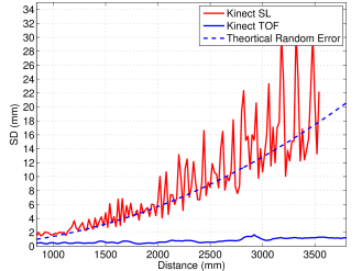
4.5.2 Planarity – Evaluation and Results
The region-of-interest in each range image acquired using the rail lies on a planar wall, so the resulting range measurements should ideally result in a plane. Similar to Khoshelham and Elberink [26], we apply a RANSAC plane fitting method to avoid outliers and calculate the standard deviation of the points from the fitted plane as planarity error.
Fig. 16 shows the planarity error as SD for both Kinect and the theoretical random error deduced by Khoshelham and Elberink [26] for the Kinect. The Kinect delivers much stronger out-of-plane errors than the Kinect, which stays below mm for the whole range of m. The curve for the Kinect is roughly within the expected range. Compared to Khoshelham and Elberink [26] we observe an additional fluctuation which can be explained by the decreasing depth resolution of the Kinect which leads to a significant depth quantization for increasing distances.
4.5.3 Intensity (Kinect only)
Similar to Lindner and Kolb [35] we evaluate the planar checkerboard with varying gray-levels at m distance. For this scenario we select horizontal pixel lines across the gray-level rectangles and directly plot the distance values for several distances to the wall. Fig. 17 shows, that the Kinect delivers very stable results and the range error for the darkest rectangle is max. mm, compared to the white reference distance. Compared to earlier ToF-camera prototypes, for which range errors up to mm have been observed [35], this is a significant improvement of quality.
4.6 Semitransparent Liquid
Goal
This test scenario is designed in order to evaluate the effects of translucent, i.e. semitransparent and scattering material on the quality of the acquired object geometry.
Experimental Setup
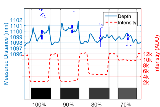
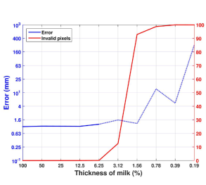
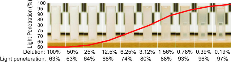
Similar to Hansard et al. [18] we use a sequence of semitransparent liquids, i.e. a plastic cylinder filled with diluted milk. The cylinder has an inner and outer diameter of and mm, respectively. By diluting the milk with the same amount of water in each step, we get sequence of objects with an amount of , i.e. %,…,% milk. We acquire frames for each setup. The cylinders are acquired from frontal view at a distance of m.
Fig. 18, bottom, the visual appearance of the milk probes is shown. The diluted milk is filled in cuvettes of cm square cross section and placed in front of a checkerboard in order to demonstrate the degree transparency in the visual range.
In order to provide a quantitative transparency degree, we measured the light penetration through the cuvettes at nm. The measured intesity through a cuvette filled with water was the reference
and each sample was divided by the reference. The Kodak Wratten nm filter explained at 4.2 was applied to filter visible light.
Evaluation and Results
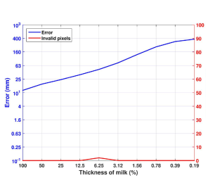
Same as Hansard et al. [18] we directly measure the signed error in depth for a manually segmented region in the range image with respect to the mean image as a function of transparency by comparing against a reference measurement with a non-transparent cylinder of the same size; see Eq. (5). Furthermore, we plot the number of invalid pixels.
As can be seen in Fig.18, top-left, Kinect performs very well for liquid samples with more than % milk, with almost no invalid pixels and a signed error in the range of mm, which is around the thickness of the plastic cylinder. However, for the samples with concentration of milk below %, the number of invalid pixels increases dramatically to above % and the depth error of the remaining valid pixels is increasing as well. For the same experiments the Kinect shows a positive distance error between and mm, but does not mark any measurements as invalid, i.e. the number of invalid pixels is negligible; see Fig.18, top-right. However, for the samples thinner than %, the number of invalid pixels increases dramatically to above % for the Kinect while Kinect still delivers valid pixels with rising error up to mm for % milk. In conclusion, Kinect performs good for thicker semitransparent liquids and indicates failure for the thinner cases. On the other hand, using the Kinect is much harder, as the device does not indicate the pixel’s invalidity even for a large amount of distance error.
4.7 Reflective Board
Goal
This test evaluates the impact of strongly reflecting objects which potentially result in erroneous depth measurements mainly due to multi-path effects. Beside the reflectivity as such, the multi-path effect strongly depends on the orientation of the reflective object towards other bright objects in the scene and the camera. Therefore, we are mainly interested in the relation between the angular orientation and measured depth error.
Experimental Setup
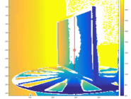
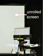
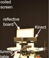
We use a common whiteboard of cm size as reflective object and place it vertically on a turning table in front of a white projector screen at a distance of cm from the camera. The projector screen can be rolled up and behind that there is a non-reflecting black curtain in order to make a non-multi-path reference measurements; see Fig. 19, middle and right. The rotating vertical board is placed in front of the Kinect camera so that the board rotates around the pivot line which intersects the center of the rotating table. The points lying on the pivot line remain at the same distance to the camera. The rotation starts from to with resolution of . The specific multi-path effect depends on the board angle. For each step we acquire frames.
Evaluation and Results
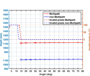
For each acquired pair of range images, i.e. for a given fixed angle, with a coiled and unrolled screen, we select a vertical pixel region of interest around the rotation pivot on the whiteboard. For each pixel in the vertical region of interest we assume a constant distance to the camera and a constant multi-path situation. Within this region we compute the RMSE with respect to the reference measurement at and the SD of the measurement itself as a function of the incident angle. Furthermore, we calculate the relative number of invalid pixels.
 |
 |
| Kinect | Kinect |
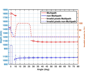
In Fig. 20 the RMSE and the SD for all acquisition angles for the Kinect (left) and the Kinect (right) are plotted. Additionally, we plot the amount of invalid pixel. As expected, the Kinect has much less problem with this indirect lighting setup, since the structured light principle does not get confused by diffuse scattered light. However, the Kinect has also limitations for low angles and delivers a higher invalid depth for low incident angles. Even though the measurement principle should not get affected by this. One simple explanation would be, that too little light is getting reflected to the camera, however, this would also be true for the reference measurement with coiled screen.
For incident angles below up to % of the pixels are marked invalid. For angles above , the Kinect yields nearly no invalid pixels and the depth error is close to zero. The Kinect, on the other hand, has a lot more problems with the superposition of the indirect illumination, i.e. the multi-path situation. Apparently, the Kinect is able to detect some of the corrupted pixel, but at angles below which get affected by a low incident angle, are not classified as invalid, resulting in extremely range errors up to mm. For incident angles between and the Kinect delivers up to % invalid pixel. Similar as for the Kinect, the Kinect range values are again more reliable for angles above , i.e. no invalid pixels are delivered with a depth error below mm.
4.8 Turning Siemens Star

Goal
The performed test targeted at measuring the amount of flying pixels, i.e.pixels that cover an inhomogeneous region in terms of depth and thus do not deliver proper depth values, for static and dynamic scenes. Both Kinect cameras mark unreliable pixels as “invalid”, which also applies for the flying pixels.
Experimental setup
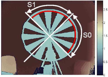
Similar to Lottner et al. [36] we manufactured a 3D Siemens star. However, we mount it to a stepping motor that actuates the star in a controlled fashion in front of a planar background wall at m distance. The geometrical dimensions of the Siemens star are shown in Fig. 21, left. We apply different angular velocity while capturing range data with any of the Kinect cameras. As the both Kinects have different intrinsic parameters and different range image resolution, there are different options for the geometric setup of the measurement. We opted for a setup where each sensor has the same “pixel coverage” on the star, thus the cameras have different distances to the star during the acquisition, but as both cameras have approximately the same temporal resolution, i.e. frame rate, pixel coverage for the lateral motion is comparable for both Kinect.
We acquire range data for the static and the dynamic wheel. We have chosen nine velocity steps between RPM. In our setup RPM relates to pixel swept in the most outer circle (red arc in Fig 21, right) by the wheel within one range image, i.e. in s.
 |
 |
 |
 |
Evaluation and Results
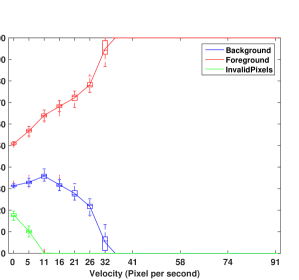
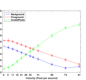
In the evaluation we account for the fact, that the Kinect’s illumination units are mounted horizontally for both cameras, leading to different shadowing effects at vertical and horizontal edges. Thus we expected varying results between regions with predominantly vertical and horizontal edges and performed the analysis separately for the two wheel quarters, one at the right (“S0”) and one at the top (“S1”). For the evaluation we use pixels at a circular arc at the outer part of the wheel illustrated by the red arc; see in Fig 21, right.
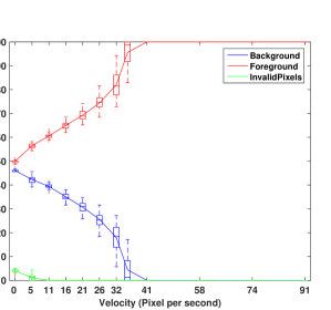
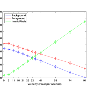
In an ideal case, along the arcs there should be 50% foreground and 50% background pixels. Therefore we simply calculate the minimal, mean and maximal relative numbers of foreground, background and invalid pixels for the different speed values.
Fig. 22 shows the results of the foreground-background analysis for both cameras and both segments. One first insight is, that the classification results are very stable, namely the Kinect shows very little variation in its results. Comparing the classification results for the static scene, i.e. the flying pixels, the foreground classification is nearly perfect, i.e. % for the Kinect and % for the Kinect for segment “S0”. The amount of invalid pixel for this segment is % for the Kinect and % for the Kinect.
For increasing speed, it is apparent that the Kinect delivers less invalid pixels and more (false) foreground pixels , resulting in % foreground pixels for RPM. The behavior of the Kinect is much more reliable. As one would expect, the number of invalid pixels increases for higher speed and the number of foreground and background pixel decreases in a comparable way. However, there are always more foreground than background pixel. This effect can be explained by the shadowing which only applies to the background, i.e. the holes in the Siemens star.
As expected, there are differences between the two arc segments for both Kinect. In general, the results for the top segment “S1” are worse for both devices, as shadowing effects are stronger for vertical edges. For the Kinect mainly the number of invalid pixels is higher for lower speed, which is counter-intuitive. For the Kinect the differences between the two segments are less prominent.
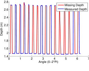
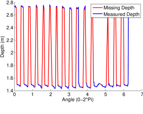
Beside the classification for the pixels along the arc, Fig. 23 shows the range profile for RPM and RPM for the full outer pixel circle. This profile plot shows an additional range distortion effect at the edges of the foreground parts. Here, additional “overshooting” effects occur, which are due to motion artifacts apparent to ToF cameras; see Sec. 2.3.
5 Conclusion
This paper presents an in-depth comparison between the two versions of the Kinect range sensor, i.e. the Kinect, which is based on the Structured Light principle, and the new Time-of-Flight variant Kinect. We present a framework for evaluating Structured Light and Time-of-Flight cameras, such as the two Kinect variants, for which we give detailed insight here. Our evaluation framework consists of seven experimental setups that cover the full range of known artifacts for these kinds of range cameras.
| Kinect | Kinect |
| Ambient Background Light (Sec. 4.2) | |
|
Below W: IP=0%, SDmm
Above mW: IP=% |
Below mW: IP=0%, SDmm
Below mW: IP=0%, SDmm At mW: IP=0%, SDmm |
| Multi-Device Interference (Sec. 4.3) | |
|
IP: % (evenly distributed)
Frame : RMSE w/o interf. mm, RMSE w interf. mm Rest of frames: RMSE w/o interf.mm, RMSE w interf.mm |
IP: % (repetitively blocked)
RMSE w/o interf. mm RMSE w interf. mm, |
| Temperature Drift (Sec. 4.4) | |
|
Before 10’: RMSE mm,
SDA mm
After 10’: RMSE rising from to mm, SDA mm |
RMSE mm & SDA mm |
| Linearity Error (Sec. 4.5.1); Pt#1 (center)…Pt#4 (corner); Kinect below m | |
|
SE1,
SE2mm,
SE3mm,
SE4mm
SD1-3mm, SD4mm |
SE1mm
SE2mm,
SE3mm,
SE4mm
SD1-3mm, SD4mm |
| Systematic Error: Planarity (Sec. 4.5.2) | |
|
SD(m)mm,
SD(m)mm, SD(m)mm |
SDmm |
| Intensity Related Error (Sec. 4.5.3) | |
| –not applicable– | distance error mm@ 1m distance |
| Semitransparent Media & Scattering (Sec. 4.6) | |
| Light Penetration %: | |
| SEmm, IP% | SEmm, IP% |
| Kinect | Kinect |
|---|---|
| Multipath Effect (Sec. 4.7) | |
|
Incid. angle :
IP%,
Incid. angle : IP%, Err. mm |
Incid. angle :
IP%,
Err.mm
Incid. angle : IP% Incid. angle : IP%, Err. mm |
| Depth Inhomogeneity and Dynamic Scenery (Sec. 4.8) | |
|
Seg. “S0”:
FG from to %, SDmm,
BG from to %, SDmm,
IP from to %, SDmm
Seg. “S1”: FG from to %, SDmm, BG from to %, SDmm, IP from to %, SDmm |
Seg. “S0”:
FG from to %, SDmm,
BG from to %, SDmm,
IP from to %, SDmm
Seg. “S1”: FG from to %, SDmm, BG from to %, SDmm, IP from to %, SDmm |
![[Uncaptioned image]](/html/1505.05459/assets/x52.png)
Device Selection Hints
Since device selection is highly application dependent, Tab. 5 sets up some rules of thumb to help users to make a more profound decision on which device to select depending on their application circumstances. The table compares device performance in different conditions with respect to the main error sources discussed above. For each source, we define two modes of operation, i.e. two ranges of application parameters. For each mode, we state a failure weight which is the performance ratio for both Kinect cameras. The individual failure values are deduced by combining error values and the number of valid pixels for each mode. Based on the individual failure values we compute the ratio between the Kinectand the Kinectfailure, whereby a ratio close to 1 means that both devices perform quite similarly, whereas values close to 0 or close to infinity indicate, that Kinectand Kinecthave relatively high failure rates, respectively. For a specific application scenario, the user selects relevant error sources and by multiplying the failure ratios, the overall failure ratio is computed. If this final ratio is smaller than 1, Kinectwould be the best choice, otherwise Kinectis preferable. Of course, this is only a very coarse but quick guideline resulting in a first suggestion. The user should in any case have a further look at the details for the error sources that are most relevant to the specific application.
Note, that we dropped the error sources “Intensity Related Error” and “Multi-Device Interference” from Tab. 4, because the “Intensity Related Error” applies only to Kinectand has, compared to prior ToF devices only very little impact. Furthermore, if “Multi-Device Interference” is essential to the application, further actions need to be applied, such as using “Shake‘n’Sense” in case of Kinect[7] or different modulation frequencies in case of the Kinect.
Example 1: User A requires a depth sensing device for indoor scene reconstruction where the scene has static semi reflective surfaces at high angles:
Failure ratio = =
Therefore Kinectwould absolutely fail in this application.
Example 2: User B requires face gesture recognition at 1.2 meter distance in indoor office conditions:
Failure ratio = =
As the failure ratio is more than 1, user B should choose Kinect for his application.
Open Science
We have prepared a website to make the following material publicly available:
-
1.
A documented version of the evaluation scripts for all experiments written in Matlab.
-
2.
Further technical details for setting up the required test scenarios, e.g. a CAD file for the Siemens star, intensity and calibration checker board.
The website is available for use by other researchers
at:
http://www.cg.informatik.uni-siegen.de/data/KinectRangeSensing/.
Acknowledgment
The authors would like to thank Microsoft Inc. for making the prototype of the Kinect-cameras available via the Kinect For Windows Developer Preview Program (K4W DPP) and Dr. Rainer Bornemann from the Center for Sensor Systems of Northrhine-Westphalia (ZESS), Siegen, for the reference measurements of the illumination signal for the Kinect camera and for the support in measuring the ambient illumination.
References
- Bauer et al. [2013] Bauer, S., Seitel, A., Hofmann, H., Blum, T., Wasza, J., Balda, M., Meinzer, H.-P., Navab, N., Hornegger, J., & Maier-Hein, L. (2013). Real-time range imaging in health care: A survey. In M. Grzegorzek, C. Theobalt, R. Koch, & A. Kolb (Eds.), Time-of-Flight and Depth Imaging. Sensors, Algorithms, and Applications (pp. 228–254). Springer volume 8200 of Lecture Notes in Computer Science.
- Beder et al. [2007] Beder, C., Bartczak, B., & Koch, R. (2007). A comparison of pmd-cameras and stereo-vision for the task of surface reconstruction using patchlets. In Proc. IEEE Int. Conf. on Computer Vision and Pattern Recognition, 2007. (pp. 1–8). IEEE.
- Berger et al. [2013] Berger, K., Meister, S., Nair, R., & Kondermann, D. (2013). A state of the art report on kinect sensor setups in computer vision. In M. Grzegorzek, C. Theobalt, R. Koch, & A. Kolb (Eds.), Time-of-Flight and Depth Imaging. Sensors, Algorithms, and Applications (pp. 257–272). Springer volume 8200 of Lecture Notes in Computer Science.
- Berger et al. [2011] Berger, K., Ruhl, K., Brümmer, C., Schröder, Y., Scholz, A., & Magnor, M. (2011). Markerless motion capture using multiple color-depth sensors. In Proc. Vision, Modeling and Visualization (VMV) 2011 (pp. 317–324).
- Blake et al. [2015] Blake, J., Echtler, F., & Kerl, C. (2015). OpenKinect: Open source drivers for the kinect for windows v2 device. https://github.com/OpenKinect/libfreenect2. Last visited: Jan. 26th, 2015.
- Bradski [2000] Bradski, G. R. (2000). The OpenCV Library. Dr. Dobb’s Journal of Software Tools, .
- Butler et al. [2012] Butler, A., Izadi, S., Hilliges, O., Molyneaux, D., Hodges, S., & Kim, D. (2012). Shake’n’sense: Reducing structured light interference when multiple depth cameras overlap. In Proc. Human Factors in Computing Systems (ACM CHI). New York, NY, USA: ACM.
- Dorrington et al. [2011] Dorrington, A., Godbaz, J., Cree, M., Payne, A., & Streeter, L. (2011). Separating true range measurements from multi-path and scattering interference in commercial range cameras. In Proc. IS&T/SPIE Electronic Imaging (pp. 786404–786404).
- Droeschel et al. [2010] Droeschel, D., Holz, D., & Behnke, S. (2010). Multi-frequency phase unwrapping for time-of-flight cameras. In Intelligent Robots and Systems (IROS), 2010 IEEE/RSJ International Conference on (pp. 1463–1469). IEEE.
- El-laithy et al. [2012] El-laithy, R., Huang, J., & Yeh, M. (2012). Study on the use of microsoft kinect for robotics applications. In Proc. IEEE Symp. on Position Location and Navigation (PLANS) (pp. 1280–1288).
- Evangelidis et al. [2015] Evangelidis, G., Hansard, M., & Horaud, R. (2015). Fusion of range and stereo data for high-resolution scene-modeling, .
- Falie & Buzuloiu [2008] Falie, D., & Buzuloiu, V. (2008). Distance errors correction for the time of flight (ToF) cameras. In Proc. European Conf. on Circuits and Systems for Communications (pp. 193–196).
- Fechteler et al. [2007] Fechteler, P., Eisert, P., & Rurainsky, J. (2007). Fast and high resolution 3D face scanning. In International Conference on Image Processing (ICIP) (pp. 81–84). volume 3.
- Fiedler & Müller [2013] Fiedler, D., & Müller, H. (2013). Impact of thermal and environmental conditions on the kinect sensor. In Advances in Depth Image Analysis and Applications (pp. 21–31). Springer.
- Gallo et al. [2011] Gallo, L., Placitelli, A. P., & Ciampi, M. (2011). Controller-free exploration of medical image data: Experiencing the kinect. In Proc. IEEE Int. Symp. Computer-Based Medical Systems (CBMS) (pp. 1–6). IEEE.
- Hall-Holt & Rusinkiewicz [2001] Hall-Holt, O., & Rusinkiewicz, S. (2001). Stripe boundary codes for real-time structured-light range scanning of moving objects. In Proc. IEEE Int. Conf. on Computer Vision (ICCV) (pp. 359–366). volume 2.
- Han et al. [2013] Han, J., Shao, L., Xu, D., & Shotton, J. (2013). Enhanced computer vision with microsoft Kinect sensor: A review. IEEE Transactions on Cybernetics, 43, 1318–1334.
- Hansard et al. [2013] Hansard, M., Lee, S., Choi, O., & Horaud, R. (2013). Time-of-flight cameras: Principles, Methods, and Applications. Springer.
- Herrera C. et al. [2012] Herrera C., D., Kannala, J., & Heikkilä, J. (2012). Joint depth and color camera calibration with distortion correction. IEEE Trans. Pattern Anal. Mach. Intell., 34, 2058–2064.
- Högg et al. [2013] Högg, T., Lefloch, D., & Kolb, A. (2013). Real-time motion artifact compensation for PMD-ToF images. In Proc. Workshop Imaging New Modalities, German Conference of Pattern Recognition (GCPR) (pp. 273–288). Springer volume 8200 of LNCS.
- Ihrke et al. [2010] Ihrke, I., Kutulakos, K. N., Lensch, H., Magnor, M., & Heidrich, W. (2010). Transparent and specular object reconstruction. In Computer Graphics Forum (pp. 2400–2426). volume 29.
- Kadambi et al. [2013] Kadambi, A., Whyte, R., Bhandari, A., Streeter, L., Barsi, C., Dorrington, A., & Raskar, R. (2013). Coded time of flight cameras: sparse deconvolution to address multipath interference and recover time profiles. ACM Transactions on Graphics (TOG), 32, 167.
- Kahlmann et al. [2007] Kahlmann, T., Remondino, F., & Guillaume, S. (2007). Range imaging technology: new developments and applications for people identification and tracking. In Proc. of Videometrics IX - SPIE-IS&T Electronic Imaging. volume 6491. DOI: 10.1117/12.702512.
- Kahlmann et al. [2006] Kahlmann, T., Remondino, F., & Ingensand, H. (2006). Calibration for increased accuracy of the range imaging camera SwissRanger™. Image Engineering and Vision Metrology (IEVM), 36, 136–141.
- Keller et al. [2013] Keller, M., Lefloch, D., Lambers, M., Izadi, S., Weyrich, T., & Kolb, A. (2013). Real-time 3D reconstruction in dynamic scenes using point-based fusion. In Proc. of Joint 3DIM/3DPVT Conference (3DV) (p. 8).
- Khoshelham & Elberink [2012] Khoshelham, K., & Elberink, S. O. (2012). Accuracy and resolution of kinect depth data for indoor mapping applications. Sensors, 12, 1437–1454. URL: http://www.mdpi.com/1424-8220/12/2/1437. doi:10.3390/s120201437.
- Kim et al. [2009] Kim, Y. M., Theobalt, C., Diebel, J., Kosecka, J., Miscusik, B., & Thrun, S. (2009). Multi-view image and tof sensor fusion for dense 3d reconstruction. In Proc. Int. IEEE Conf. on Computer Vision Workshops (ICCV Workshops) (pp. 1542–1549). IEEE.
- Kolb et al. [2010] Kolb, A., Barth, E., Koch, R., & Larsen, R. (2010). Time-of-flight cameras in computer graphics. J. Computer Graphics Forum, 29, 141–159.
- Konolige & Mihelich [2012] Konolige, K., & Mihelich, P. (2012). OpenKinect: Ros’ technical description of kinect calibration. http://wiki.ros.org/kinect_calibration/technical. Last edited: Dec. 27th, 2012.
- Kuhnert & Stommel [2006] Kuhnert, K., & Stommel, M. (2006). Fusion of stereo-camera and PMD-camera data for real-time suited precise 3D environment reconstruction. In Intelligent Robots and Systems (IROS) (pp. 4780–4785).
- Langmann et al. [2012] Langmann, B., Hartmann, K., & Loffeld, O. (2012). Depth camera technology comparison and performance evaluation. In International Conference on Pattern Recognition Applications and Methods (ICPRAM) (pp. 438–444).
- Lefloch et al. [2013] Lefloch, D., Nair, R., Lenzen, F., Schäfer, H., Streeter, L., Cree, M., Koch, R., & Kolb, A. (2013). Technical foundation and calibration methods for time-of-flight cameras. In M. Grzegorzek, C. Theobalt, R. Koch, & A. Kolb (Eds.), Time-of-Flight and Depth Imaging. Sensors, Algorithms, and Applications (pp. 3–24). Springer volume 8200 of Lecture Notes in Computer Science.
- Lindner & Kolb [2006] Lindner, M., & Kolb, A. (2006). Lateral and depth calibration of pmd-distance sensors. In Proc. Int. Symp. on Visual Computing LNCS (pp. 524–533). Springer.
- Lindner & Kolb [2009] Lindner, M., & Kolb, A. (2009). Compensation of motion artifacts for Time-of-Flight cameras. In Proc. Dynamic 3D Imaging (pp. 16–27). Springer volume 5742 of LNCS.
- Lindner et al. [2010] Lindner, M., Schiller, I., Kolb, A., & Koch, R. (2010). Time-of-flight sensor calibration for accurate range sensing. Computer Vision and Image Understanding, 114, 1318–1328.
- Lottner et al. [2011] Lottner, O., Langmann, B., Weihs, W., & Hartmann, K. (2011). Scanning 2d/3d monocular camera. In Proc. 3DTV Conference: The True Vision-Capture, Transmission and Display of 3D Video (pp. 1–4).
- Macknojia et al. [2013] Macknojia, R., Chávez-Aragón, A., Payeur, P., & Laganière, R. (2013). Calibration of a network of kinect sensors for robotic inspection over a large workspace. In IEEE Workshop on Robot Vision (WORV) (pp. 184–190). IEEE.
- Meister et al. [2012] Meister, S., Izadi, S., Kohli, P., Hämmerle, M., Rother, C., & Kondermann, D. (2012). When can we use KinectFusion for ground truth acquisition? In Proc. Workshop on Color-Depth Camera Fusion in Robotics.
- Nair et al. [2013a] Nair, R., Meister, S., Lambers, M., Balda, M., Hofmann, H., Kolb, A., Kondermann, D., & Jähne, B. (2013a). Ground truth for evaluating time of flight imaging. In M. Grzegorzek, C. Theobalt, R. Koch, & A. Kolb (Eds.), Time-of-Flight and Depth Imaging. Sensors, Algorithms, and Applications (pp. 52–74). Springer volume 8200 of Lecture Notes in Computer Science.
- Nair et al. [2013b] Nair, R., Ruhl, K., Lenzen, F., Meister, S., Schäfer, H., Garbe, C., Eisemann, M., Magnor, M., & Kondermann, D. (2013b). A survey on time-of-flight stereo fusion. In M. Grzegorzek, C. Theobalt, R. Koch, & A. Kolb (Eds.), Time-of-Flight and Depth Imaging. Sensors, Algorithms, and Applications (pp. 105–127). Springer volume 8200 of Lecture Notes in Computer Science.
- Newcombe et al. [2011] Newcombe, R. A., Davison, A. J., Izadi, S., Kohli, P., Hilliges, O., Shotton, J., Molyneaux, D., Hodges, S., Kim, D., & Fitzgibbon, A. (2011). Kinectfusion: Real-time dense surface mapping and tracking. In Proc. IEEE Int. Symp. Mixed and Augmented Reality (ISMAR) (pp. 127–136).
- Nguyen et al. [2012] Nguyen, C. V., Izadi, S., & Lovell, D. (2012). Modeling kinect sensor noise for improved 3d reconstruction and tracking. In 3D Imaging, Modeling, Processing, Visualization and Transmission (3DIMPVT), 2012 Second International Conference on (pp. 524–530). IEEE.
- Nießner et al. [2013] Nießner, M., Zollhöfer, M., Izadi, S., & Stamminger, M. (2013). Real-time 3D reconstruction at scale using voxel hashing. ACM Transactions on Graphics (TOG), 32, 169.
- Ringbeck et al. [2007] Ringbeck, T., Möller, T., & Hagebeuker, B. (2007). Multidimensional measurement by using 3-D PMD sensors. Advances in Radio Science, 5, 135–146.
- Sabov & Krüger [2010] Sabov, A., & Krüger, J. (2010). Identification and correction of flying pixels in range camera data. In Proc. Spring Conf. on Computer Graphics (pp. 135–142).
- Schmidt & Jahne [2011] Schmidt, M., & Jahne, B. (2011). Efficient and robust reduction of motion artifacts for 3D time-of-flight cameras. In Proc. Int. Conf. 3D Imaging (IC3D) (pp. 1–8). doi:10.1109/IC3D.2011.6584391.
- Smisek et al. [2011] Smisek, J., Jancosek, M., & Pajdla, T. (2011). 3d with kinect. In IEEE Int. Conf. Consumer Depth Cameras for Computer Vision (CDC4CV) (pp. 1154–1160).
- Stoyanov et al. [2011] Stoyanov, T., Louloudi, A., Andreasson, H., & Lilienthal, A. J. (2011). Comparative evaluation of range sensor accuracy in indoor environments. In European Conference on Mobile Robots (ECMR) (pp. 19–24).
- Stoyanov et al. [2013] Stoyanov, T., Mojtahedzadeh, R., Andreasson, H., & Lilienthal, A. J. (2013). Comparative evaluation of range sensor accuracy for indoor mobile robotics and automated logistics applications. Robot. Auton. Syst., 61, 1094–1105.
- Vera et al. [2011] Vera, L., Gimeno, J., Coma, I., & Fernández, M. (2011). Augmented mirror: interactive augmented reality system based on kinect. In Human-Computer Interaction–INTERACT (pp. 483–486). Springer volume 6949 of LNCS.
- Wiedemann et al. [2008] Wiedemann, M., Sauer, M., Driewer, F., & Schilling, K. (2008). Analysis and characterization of the pmd camera for application in mobile robotics. In Proc. IFAC World Congress (pp. 6–11).
- Xu et al. [2013] Xu, Z., Perry, T., & Hills, G. (2013). Method and system for multi-phase dynamic calibration of three-dimensional (3D) sensors in a time-of-flight system. US Patent 8,587,771.
- Xu et al. [1998] Xu, Z., Schwarte, R., Heinol, H., Buxbaum, B., & Ringbeck, T. (1998). Smart pixel – photonic mixer device (PMD). In Proc. Int. Conf. on Mechatron. & Machine Vision (pp. 259–264).
- Zach et al. [2007] Zach, C., Pock, T., & Bischof, H. (2007). A duality based approach for realtime TV-L 1 optical flow. In Proc. German Conference on Pattern Recognition (DAGM) (pp. 214–223). Springer.
- Zhang et al. [2002] Zhang, L., Curless, B., & Seitz, S. M. (2002). Rapid shape acquisition using color structured light and multi-pass dynamic programming. In IEEE Int. Sym. on 3D Data Processing, Visualization, and Transmission (pp. 24–36).
- Zhang & Huang [2004] Zhang, S., & Huang, P. (2004). High-resolution, real-time 3D shape acquisition. In Proceedings of the 2004 Conference on Computer Vision and Pattern Recognition Workshop (CVPRW) (pp. 28–36). Washington, DC, USA: IEEE Computer Society volume 3.
- Zhang [2000] Zhang, Z. (2000). A flexible new technique for camera calibration. Pattern Analysis and Machine Intelligence, IEEE Transactions on, 22, 1330–1334.