Nonreciprocal spin wave propagation in chiral-lattice ferromagnets
Abstract
Spin current, i.e. the flow of spin angular momentum or magnetic moment, has recently attracted much attention as the promising alternative for charge current with better energy efficiency. Genuine spin current is generally carried by the spin wave (propagating spin precession) in insulating ferromagnets, and should hold the chiral symmetry when it propagates along the spin direction. Here, we experimentally demonstrate that such a spin wave spin current (SWSC) shows nonreciprocal propagation characters in a chiral-lattice ferromagnet. This phenomenon originates from the interference of chirality between the SWSC and crystal-lattice, which is mediated by the relativistic spin-orbit interaction. The present finding enables the design of perfect spin current diode, and highlights the importance of the chiral aspect in SWSC.
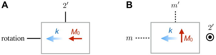
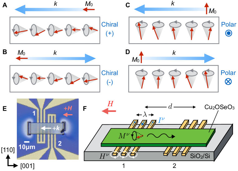
Electron is a particle characterized by the charge and spin degree of freedom. In contrast to the charge current accompanied by Joule heat loss, spin current can be dissipationless and potentially minimize the energy consumption associated with the information processingSC_Review ; SpinCurrentMurakami ; SpinHallExp ; SpinHallTheory . Spin current is generally carried by the spin-polarized conduction electrons in metallic system, as well as the spin wave in insulating systemYIG_SP ; YIG_SSE . In particular, the latter spin wave spin current (SWSC) possesses many advantages over the former one, since it can avoid the simultaneous flow of charge current and has much longer propagation length. From the viewpoint of the symmetry, there are two types of SWSC for ferromagnets, depending on the directional relationship between the carried magnetic moment (parallel to the external magnetic field ) and the wave vector . In case of (Fig. 1A), the SWSC doesn’t have any mirror plane or space-inversion center, and belongs to the chiral symmetrySW_Symmetry ; comment . In contrast, the SWSC with configuration (Fig. 1C) has the polar symmetry with the polar axis normal to both and . For each case, the reversal of gives the SWSC with opposite chirality or polarity (Fig. 1, B and D).
The above analysis predicts that the SWSCs propagating along the positive and negative direction can show different propagation characters, when placed in the chiral or polar environment depending on the symmetry of SWSC. For example, the surface (or interface) is always characterized by the structural polarization normal to the surface. When both and are confined within the surface plane keeping the relationship, the polar axis of SWSC (Fig. 1, C and D) becomes parallel or antiparallel to the polarization of the surface and thus the asymmetric spin wave propagation between can be expected. Such a surface-induced spin wave nonreciprocity has first been predicted by Damon and Eshbach more than 50 years agoDEFirst , and then verified by various experimental techniques such as spin wave spectroscopySurface_YIG ; MSW_Text , spin-polarized electron energy loss spectroscopySW_DM_SPEEL , thermographyUniHeat , and Brillouin light scatteringSW_DM_BLS . In particular, the mode mediated by the magnetic dipole-dipole interaction in this configuration is called magnetostatic surface wave (representing that it can propagate only at the surface of the sample), and is known for its unidirectional propagation characterDEFirst ; MSW_Text ; MSW_Text2 . Nevertheless, such a surface-driven nonreciprocity mostly cancels out as the entire sample, since the sign of polarity is generally opposite between the top and bottom surfaces.
In contrast, the interplay between the SWSC and the chiral medium has hardly been investigated. One reason is that the coexistence of crystallographic chirality and ferromagnetism is very rare in the real materials. Recently, however, some metallic ferromagnets with the chiral B20 crystallographic lattice (such as MnSi, Fe1-xCoxSi, and FeGe) have been found to host magnetic skyrmions, i.e. nanometer-sized vortex-like swirling spin texture with particle natureSkXTheory ; NeutronMnSi ; TEMFeCoSi ; SkXReviewTokura . Skyrmions are now attracting much attention as the potential information carrier for the high-density magnetic storage deviceSkXReviewTokura ; SkXReviewFert , and the above finding has promoted further search of similar chiral-lattice ferromagnetic materials. Soon after their discovery in the B20 materials, it has been reported that a chiral-lattice ferromagnetic insulator Cu2OSeO3 (with cubic space group ) can also host magnetic skyrmions, for the narrow temperature region just below KCu2OSeO3_Seki ; Cu2OSeO3_SANS_Seki ; Cu2OSeO3_SANS_Pfleiderer ; Onose . Notably, this material offers an ideal opportunity to investigate the property of SWSC under the chiral environment. In this work, we have examined the nonreciprocal nature of spin wave propagation for this chiral-lattice magnet in terms of spin wave spectroscopy.
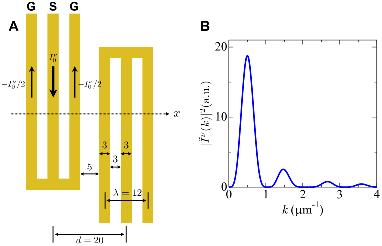
The basic concept of the spin wave spectroscopyAESWS_doppler_Science ; AESWS_doppler_B as well as the employed device structure is summarized in Fig. 1, E and F. A pair of Au coplanar waveguides (ports 1 and 2) were fabricated on the oxidized silicon substrate, and the plate-shaped single crystal of Cu2OSeO3 was placed across them. Here, the chirality of each Cu2OSeO3 crystal (D or L) is checked by measuring the natural optical activity at light wavelength 1310 nm in advance. When the oscillating electric current of gigahertz frequency is injected into one of the waveguides, generates oscillating magnetic field and excites spin wave (i.e. coherent magnetization oscillation ) in the Cu2OSeO3 sample. The propagating spin wave causes an additional magnetic flux on the waveguides, and induces the oscillating electric voltage following the Faraday’s law. By measuring the spectrum of complex inductance as defined by (with and representing the port numbers used for the excitation and detection, respectively) with the vector network analyzer (VNA), we can evaluate both magnitude and phase of propagating spin wave. The spin wave contribution to the inductance spectrum is derived by the subtraction of the common background from the raw data . Here, taken at Oe is adopted as , where the magnetic resonance is absent within our target frequency range from 2GHz to 7GHz. The wave number of excited spin wave is determined by the spatial periodicity m) of the waveguide pattern and the associated current density AESWS_doppler_Science ; AESWS_doppler_B . Its Fourier transform has the main peak at m-1 with the full width at half maximum (FWHM) of m-1 as plotted in Fig. 4C, satisfying the relationship . To investigate the property of SWSC of the chiral symmetry (Fig. 1, A and B), the configuration is always adopted here. In this setup, the mode is called magnetostatic backward volume wave, which propagates through the entire volume of the sample with the negative group velocityDEFirst ; MSW_Text ; MSW_Text2 . In the centrosymmetric materials, this mode should not show any nonreciprocal propagation nature.
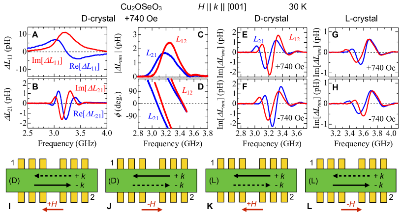
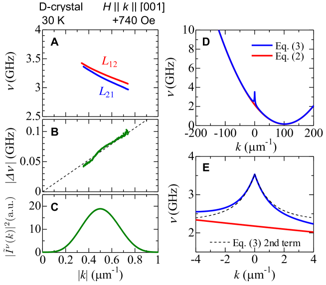
First, we have investigated the nature of SWSC in the uniform collinear ferromagnetic state with saturated magnetization. Figure 2, A and B indicate the real and imaginary part of and spectra measured at +740 Oe, i.e. in the collinear ferromagnetic state, for the D-chirality of the Cu2OSeO3 crystal. The self-inductance represents the efficiency of the local spin wave excitation, and the ferromagnetic resonance characterized by Lorentzian shape of spectrum can be identified at 3.2 GHz. In contrast, the mutual-inductance reflects the propagation character of spin wave between the two waveguides, and the finite oscillating signal can be detected around the same resonance frequency. Hereafter, we focus on the comparison between and , each of which stands for the propagating spin wave characterized by the wave vector and , respectively. To interpret the data more intuitively, the spectra of and as defined with Re Im are plotted in Fig. 2, C and D. and express the magnitude of spin wave after the propagation along the positive and negative directions, and both spectra show a peak structure. Notably, the peak frequency as well as the peak intensity are clearly different between . On the other hand, represents the phase delay of spin wave for a transmission between the two waveguides separated by the distance m), and will satisfy the relationship when a single spin wave mode is assumedAESWS_doppler_Science ; AESWS_doppler_B . This means that the spectrum directly reflects the spin wave dispersion relationship, and its slope gives the group velocity . The clear difference in the slope between the ones derived from and indicates that of spin wave is not equal between . The above results establish that the propagation character of spin wave in this configuration is nonreciprocal, from both aspects of magnitude and group velocity.
To reveal the origin of nonreciprocity, the measurements of Im[] and Im[] were performed with various combinations of the magnetic field direction ( Oe) and crystallographic chirality (D and L) for Cu2OSeO3 (Fig. 2, E to H). Figure 2E shows the data for the D-crystal at Oe. The spectra of Im[] and Im[] are characterized by the signal oscillating with different period and magnitude, in agreement with the feature observed for and . For the opposite sign of applied (Fig. 2F), the spectral shapes for Im[] and Im[] (i.e. the sign of nonreciprocity) are reversed. Likewise, the employment of opposite chirality of crystal (i.e. L-crystal) also reverses the sign of nonreciprocity (Fig. 2, G and H). In Fig. 2, I to L, the symmetrically expected sign of nonreciprocity for each experimental configuration is summarized. In general, the SWSC is expressed as the product of magnetic moment () and wave vector (Fig. 1, A and B). This means that -reversal has the same effect as -reversal, and thus results in the opposite sign of nonreciprocity. On the other hand, the application of space-inversion operation to the system reverses both the crystallographic chirality and the -direction keeping and unchanged, indicating that the sign of nonreciprocity should be opposite between L-crystal and D-crystal. The above symmetry-based analysis is in agreement with the experimental results, which proves that the observed spin wave nonreciprocity originates from the chiral nature of crystal lattice.
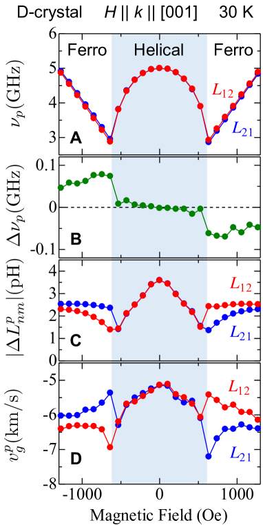
Next, we investigated the magnetic field dependence of nonreciprocity. In Fig. 3, A and B, the peak frequency for and (defined as and ), as well as the difference between them , are plotted as a function of . Cu2OSeO3 is known to host the helical spin order for Cu2OSeO3_Seki ; Cu2OSeO3_SANS_Seki ; Cu2OSeO3_SANS_Pfleiderer , while it is replaced with the uniform collinear ferromagnetic order for Oe. The magnetic resonance frequency is gradually suppressed by in the helical spin state, and then shows -linear increase in the collinear ferromagnetic state. These behaviors are consistent with the previous reportsOnose ; B20_FMR ; Okamura_First . Notably, the magnitude of nonreciprocity is essentially dependent on the underlying magnetic structure. While the relatively large shift of resonance frequency GHz between is always observed for the collinear ferromagnetic state, such a nonreciprocity suddenly vanishes upon the transition into the helical spin state. Similar behavior is also observed for the peak intensity (Fig. 3C) and group velocity (Fig. 3D) deduced at . For all these properties, clear nonreciprocity is observed only in the collinear ferromagnetic state. Note that , , and basically reflect the frequency, magnitude, and group velocity of spin wave for . At maximum, the frequency shift GHz and the change in () up to 25 (40) can be obtained between . Their sign of nonreciprocity is confirmed to reverse for -reversal.
To clarify the microscopic origin of observed nonreciprocity, we attempt to estimate the spin wave dispersion for this material. According to Ref. Kataoka ; MnSi_Disp_New , the magnetic Hamiltonian for the ferromagnets with chiral cubic lattice symmetry under the continuum approximation can be written as
| (1) |
where , , and describe the magnitude of ferromagnetic exchange, Dzyaloshinskii-Moriya (DM), and cubic anisotropy term, respectively. is dimensionless parameter representing the vector spin density. , , , and are gyromagnetic ratio, vacuum magnetic permeability, Planck constant, and the volume of formula unit cell of Cu2OSeO3, respectively. For the configuration, the spin wave dispersion for the uniform collinear ferromagnetic state is described asKataoka
| (2) |
In the real sample, this dispersion is further modified by the additional contribution of the magnetic dipole-dipole interaction, especially for the region. When the infinitely wide plate-shaped sample with the thickness is assumed and lies along the in-plane direction, Eq. 2 can be rewritten asMSW_Text ; MSW_Text2 ; MnSi_Disp_New
| (3) |
with being the saturation magnetization. In Fig. 4, D and E, the spin wave dispersion calculated based on Eq. 3 with the material parameters estimated for Cu2OSeO3 is plotted. Equation 3 can be approximated by Eq. 2 except for the region, and gives parabolic dispersion with its minimum at . As approaches zero, however, the contribution of magnetic dipole-dipole interaction gradually increases the spin wave frequency. It causes the negative group velocity for the region, and this mode can be considered as a kind of magnetostatic backward volume waveMSW_Text ; MSW_Text2 . Note that the first and second term in Eq. 3 are odd and even functions of , respectively, and thus only the former one proportional to can contribute to the spin wave nonreciprocity. This suggests that the observed nonreciprocity directly comes from the DM interaction, whose sign and magnitude reflect the chirality of the underlying crystallographic lattice through the relativistic spin-orbit interaction.
Experimentally, the above spin wave dispersion relationship can be partly reproduced by analyzing the spectrum (Fig. 2D). Given that the frequency corresponds to the wave number and the relationship holdsAESWS_doppler_Science ; AESWS_doppler_B , the dispersion relationship can be determined by . In Fig. 4A, the spin wave dispersions for the collinear ferromagnetic state deduced from the and spectra in Fig. 2, C and D are plotted, each of which corresponds to the one for positive and negative , respectively. For both cases, the concave-up dispersions with negative slopes are obtained, consistent with the prediction of Eq. 3 for the region (Fig. 4E)MSW_Text ; MSW_Text2 ; MnSi_Disp_New . The dispersion curves for positive and negative show considerable deviation from each other, and their frequency shift is plotted in Fig. 4B. is found to be almost proportional to , which is consistent with the relationship expected from Eq. 3. The observed slope of gives J/m2, which roughly agrees with J/m2 estimated from -dependence of magnetic resonance frequencyB20_FMR . These results firmly confirm that the observed spin wave nonreciprocity stems from the DM interaction associated with the chiral nature of crystallographic lattice. Note that for the helical spin state under the magnetic Hamiltonian given by Eq. 1, it has been proposed that the Brillouin zone is folded back with the helical spin modulation period due to the expansion of magnetic unit cellKataoka ; Helimagnon_Exp . Such a folding back of magnon branch should extinguish the asymmetry between , which explains the observed disappearance of spin wave nonreciprocity in the helical spin state.
The above relationship obtained for the ferromagnetic state suggests that linearly increases for larger . Since the linewidth of the resonance peak in spectrum is mainly determined by the -distribution of waveguide for the present situation (see Supporting Online Material), the employment of the waveguide pattern with shorter wavelength and/or repeated meander shapeAESWS_doppler_Science ; AESWS_doppler_B (i.e. enhancement of and suppression of ) will completely resolve the frequency overlap of spin wave signal between . This means that for the given resonance frequency the SWSC can propagate along only one direction, and not along the opposite direction at all.
Recently, the relevance of DM interaction has also been discussed for the case of surface/interface-driven spin wave nonreciprocitySW_DM_Theory ; SW_DM_Theory2 ; SW_DM_Theory3 , through the spin-polarized electron energy lossSW_DM_SPEEL and Brillouin light scatteringSW_DM_BLS experiments. Their reported magnitudes of frequency shift between are MHz/m-1 for Pt/Co/Ni filmSW_DM_BLS and 240 MHz/m-1 for Fe double layer on W(110)SW_DM_SPEEL , while the presently observed 130 MHz/m-1 for bulk Cu2OSeO3 is comparable with these systems. Note that the nonreciprocity in Cu2OSeO3 is for the volume spin wave and originates from the chiral lattice symmetry of the bulk crystal itself, unlike the conventional case of the surface/interface-driven nonreciprocity for the surface spin wave. Since the nonreciprocal volume spin wave can avoid the cancelation of nonreciprocity between the top and bottom surface inherent to the latter situation, our present finding offers a simple and promising route for the realization of perfect spin current diode with the 100 efficiency of rectification. It may also find unique spin caloritronic applicationsYIG_SSE ; SpinCalo , such as magnetically-tunable unidirectional heat conveyerUniHeat .
From a broader perspective, any (quasi-)particle flow along the magnetic field direction should have the chiral symmetrySW_Symmetry , and will show the similar nonreciprocal propagation character in the chiral-lattice compound. This has been experimentally confirmed for the lightMChD_First ; MChD_Helical and conduction electronEMChA_First ; EMChA_Ferro , while their reported magnitude of nonreciprocity is generally very small. Our present observation of clear spin wave (or magnon) nonreciprocity in the chiral-lattice compound highlights the importance of the chiral aspect in SWSC.
References
- (1) S. Maekawa et al., Spin Current (Oxford University Press, 2012).
- (2) S. Murakami, N. Nagaosa, S. C. Zhang, Science 301, 1348 (2003).
- (3) Y. K. Kato et al., Science 306, 1910 (2004).
- (4) J. E. Hirsch, Phys. Rev. Lett. 83, 1834 (1999).
- (5) Y. Kajiwara et al., Nature 464, 262 (2010).
- (6) K. Uchida et al., Nature Mater. 9, 894 (2010).
- (7) L. D. Barron, J. Am. Chem. Soc. 108, 5539 (1986).
- (8) The proper definition of chiral symmetry is provided in Ref. SW_Symmetry . For the detail of symmetry analysis for spin current, also see Supporting Online Material.
- (9) R. W. Damon, J. R. Eshbach, J. Phys. Chem. Solids 19, 308 (1961).
- (10) L. K. Brundle, N. J. Freedman, Electron. Lett. 4, 132 (1968).
- (11) D. D. Stencil, Theory of Magnetostatic Waves (Springer, 1993).
- (12) Kh. Zakeri et al., Phys. Rev. Lett. 104 137203 (2010).
- (13) T. An et al., Nature Mater. 12, 549 (2013).
- (14) K. Di et al., Phys. Rev. Lett. 114 047201 (2015).
- (15) A. G. Gurevich, G. A. Melkov, Magnetization Oscillations and Waves (CRC Press, 1996).
- (16) U. K. Rößler, A. N. Bogdanov, C. Pfleiderer, Nature 442, 797 (2006).
- (17) S. Mühlbauer et al., Science 323, 915 (2009).
- (18) X. Z. Yu et al., Nature 465, 901 (2010).
- (19) N. Nagaosa, Y. Tokura, Nature Nanotech. 8, 899 (2013).
- (20) A. Fert, V. Cros, J. Sampaio, Nature Nanotech. 8, 152 (2013).
- (21) S. Seki et al., Science 336, 198 (2012).
- (22) S. Seki et al., Phys. Rev. B 85, 220406 (2012).
- (23) T. Adams et al., Phys. Rev. Lett. 108, 237204 (2012).
- (24) Y. Onose et al., Phys. Rev. Lett. 109, 037603 (2012).
- (25) V. Vlaminck, M. Bailleul, Science 322, 410 (2008).
- (26) V. Vlaminck, M. Bailleul, Phys. Rev. B 81, 014425 (2010).
- (27) T. Schwarze et al., Nature Mater. 14, 478 (2015).
- (28) Y. Okamura et al., Nature Comm. 4, 2391 (2013).
- (29) M. Kataoka, J. Phys. Soc. Jpn. 56, 3635 (1987).
- (30) D. Cortés-Ortuño, P. Landeros, J. Phys.: Condens. Matter 25, 156001 (2013).
- (31) M. Janoschek et al., Phys. Rev. B 81, 214436 (2010).
- (32) A. T. Costa et al., Phys. Rev. B 82, 014428 (2010).
- (33) J. H. Moon et al., Phys. Rev. B 88, 184404 (2013).
- (34) L. Udvardi, L. Szunyogh, Phys. Rev. Lett. 102 207204 (2009).
- (35) G. E. W. Bauer, E. Saitoh, B. J. Wees, Nature Mater. 11, 391 (2012).
- (36) G. L. J. A. Rikken, E. Raupach, Nature 390, 493 (1997).
- (37) S. Kibayashi et al., Nature Comm. 5, 4583 (2014).
- (38) G. L. J. A. Rikken, P. Wyder, Phys. Rev. Lett. 87, 236602 (2001).
- (39) F. Pop et al., Nature Comm. 5, 3757 (2014).
- (40) G. Meunier, M. Bertaud, J. Galy, J. Appl. Crystallogr. 9, 364 (1976).
- (41) K. H. Miller et al., Phys. Rev. B 82, 144107 (2010).
- (42) S. Ramo, J. Whinnery, T. V. Duzer, Fields and Waves in Communication Electronics (Wiley, 1965).
- (43) H. Effenberger, F. Pertlik, Monatsch. Chem. 117, 887 (1986).
- (44) J-W. G. Bos et al., Phys. Rev. B 78, 094416 (2008).
- (45) K. Kohn, J. Phys. Soc. Jpn. 42, 2065 (1977).
- (46) The authors thank M. Mochizuki, T. Arima, N. Nagaosa, D. Morikawa, Y. Tokunaga, N. Kanazawa, Y. Nii, N. Ogawa, A. Kikkawa, and X. Z. Yu for enlightening discussions and experimental helps. This work was partly supported by Grants-In-Aid for Scientific Research (Grant No. 26610109, 15H05458, 25400344, 26103002, 26103006) from JSPS and the MEXT of Japan.
I Supporting Online Material
I.1 Experimental Details
Single crystals of Cu2OSeO3 are grown by chemical vapor transport methodCOSO_First ; COSO_Growth ; Cu2OSeO3_Seki . They are cut into the plate-like shape with widest faces parallel to the (110) plane, and polished with diamond slurry and colloidal silica. D- and L-chirality of crystals are distinguished by measuring the sign of natural optical activity at light wavelength nm. Every piece of crystal shows optical rotation angle /mm, and its single-domain nature is confirmed by the observation under polarized-light microscope.
Our procedure of the measurement and data analysis associated with the spin wave spectroscopy basically follows the method proposed in Ref. AESWS_doppler_Science ; AESWS_doppler_B . A pair of coplanar waveguide patterns (ports 1 and 2) consisting of Au 195 nm / Ti 5 nm are deposited on a thermally oxidized silicon substrate using photo lithography and electron beam evaporation technique. The rectangular shape of Cu2OSeO3 crystals with typical size from 60 m 20 m 2 m to 60 m 10 m 1 m are extracted from the original bulk crystal pieces by focused ion beam micro-sampling technique, and placed across the waveguides with W deposition at both edges of the crystal. This device is put into the probe station equipped with GM refrigerator and horizontal electromagnet, and connected with a vector network analyzer (VNA) through the coaxial cable and GSG (ground-signal-ground) microprobe. The calibration is performed using Short-Open-Load-Throurgh coplanar standards. The spectrum of -parameter ( with and representing the port numbers used for the excitation and detection, respectively) is measured by VNA at various magnitudes of external magnetic field, and converted into the impedance spectrum assuming the characteristic impedance StoZ . The one at Oe is considered as the background, where no magnetic resonance appears within the target frequency range (2 GHz 7 GHz). From the subtraction of two impedance spectra, the spin wave contribution to the inductance spectrum is derived as . The input power into the waveguide is dBm within the linear response regime, which is confirmed by measuring the power dependence of spectrum around the magnetic resonance frequency. In this work, the configuration is always adopted.
II Design of coplaner waveguide and linewidth of magnetic resonance
In Fig. 5A, the coplanar waveguide pattern employed in this study is illustrated. The wavelength and propagation gap are 12 m and 20 m, respectively. Each waveguide consists of one signal line at the center and two ground lines at the both sides, which is terminated with a short circuit. When it is connected to the VNA through the GSG microprobe, the input current density for the signal and ground line is and -, respectively. By taking the Fourier transform for the spatial distribution of current density , the wavenumber distribution can be estimatedAESWS_doppler_Science ; AESWS_doppler_B as shown in Fig. 5B. The main peak at m-1 satisfies the relationship , and its full width at half maximum (FWHM) is m-1. The higher order peaks are also found for the larger region, and the second largest one is at m-1 with the amplitude 7 times smaller than that for the main peak. To simplify the discussion, we analyzed our spectra assuming that the contribution from the main peak centered at is dominant.
Such a wavenumber distribution in waveguides (Fig. 5B) directly affects the linewidth of ferromagnetic resonance. In Im[] spectrum, the FWHM for the resonance peak at frequency can be given asAESWS_doppler_B
| (4) |
with representing the intrinsic Gilbert damping parameter. In case of the present Cu2OSeO3 specimen at 740 Oe, GHz is obtained from the Im[] spectrum of Fig. 2A in the main text. Considering the corresponding averaged spin wave group velocity km/s taken from Fig. 3D in the main text, the first term in Eq. 4 gives GHz. This means that mostly reflects the wave number distribution associated with the waveguide pattern. By using GHz, we obtain the relatively small damping parameter , which is consistent with the previous reportB20_FMR . This allows us to estimate the decay length of propagating spin wave mAESWS_doppler_B .
II.1 Material properties
Our target material, Cu2OSeO3 has the chiral cubic crystal lattice with space group COSO_Structure ; COSO_Dielectric . It contains two distinctive magnetic Cu2+ () sites with the ratio of , and three-up one-down type of local ferrimagnetic spin arrangement has been reported below magnetic ordering temperature KCOSO_Dielectric ; COSO_Ferri . This material hosts helical spin order under zero magnetic field, where spins rotate within a plane normal to the magnetic modulation vector Cu2OSeO3_Seki ; Cu2OSeO3_SANS_Seki ; Cu2OSeO3_SANS_Pfleiderer . Application of magnetic field aligns parallel to and turns the spin texture into the conical one. Above the critical magnitude of magnetic field , magnetization is saturated and collinear ferrimagnetic state is stabilized. In the present study, the character of spin wave in this collinear ferrimagnetic state is mainly investigated. To simplify the analysis, we adopted the continuum approximation and treated this compound as the ferromagnetic system.
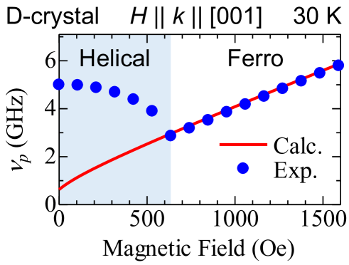
The material parameters included in Eq. 3 in the main text can be estimated so as to reproduce the -dependence of magnetic resonance frequency in the ferromagnetic state (Fig. 6). In this process, several additional confinements are imposedKataoka . The helical spin modulation period ( 62 nm)Cu2OSeO3_SANS_Seki ; Cu2OSeO3_SANS_Pfleiderer and the corresponding magnetic wave number in the ground state is given as
| (5) |
and the critical magnetic field ( T) satisfies
| (6) |
The saturation magnetization is Cu2+ at 30 K, with Å3 being the volume of formula unit cell of Cu2OSeO3. From these restrictions, we obtain J/m2, J/m, J/m3, GHz T-1, T, and . These values are used to calculate the spin wave dispersion in Fig. 4, D and E in the main text and -dependence of in Fig. 6. Similar values have also been reported in Ref. B20_FMR .
Note that Cu2OSeO3 also hosts the skyrmion spin state for narrow temperature region from 56 K to 59 K, just below Cu2OSeO3_Seki ; Cu2OSeO3_Seki ; Cu2OSeO3_SANS_Pfleiderer . Since the magnitude of propagating spin wave rapidly decays as temperature approaches , the experimental investigation of spin wave character in the skyrmion state remains the future challenge.
II.2 Symmetry of Spin Current
Spin current is generally characterized by the combination of magnetic moment and wave vector . Here, is an axial vector, and odd for time-reversal and even for space-inversion. In contrast, is a polar vector, and odd for both time-reversal and space-inversion. Thus, the spin current expressed as the product of and is even for time-reversal and odd for space-inversion.
Figure 7, A and B summarize the compatible symmetry elements for the spin current with the and configurations. In case of , the spin current sustains a rotation axis along the direction and (two-fold rotation followed by time-reversal) axis normal to it (Fig. 7A). Since no mirror plane or space-inversion center is present, this belongs to the chiral (and not polar) symmetry. In contrast, the spin current with the configuration has a mirror plane () normal to , (mirror reflection followed by time-reversal) plane normal to , and -axis normal to both and (Fig. 7B). This belongs to the polar (and not chiral) symmetry with the polar axis normal to both and .
For each configuration, the application of space-inversion operation reverses (but not ), as well as the associated sign of the chirality or polarity in the spin current.