Simultaneous Straight-line Drawing of a Planar Graph and Its Rectangular Dual
Abstract
A natural way to represent on the plane both a planar graph and its dual is to follow the definition of the dual, thus, to place vertices inside their corresponding primal faces, and to draw the dual edges so that they only cross their corresponding primal edges. The problem of constructing such drawings has a long tradition when the drawings of both primal and dual are required to be straight-line. We consider the same problem for a planar graph and its rectangular dual. We show that the rectangular dual can be resized to host a planar straight-line drawing of its primal.
1 Introduction
A planar drawing of a planar graph is its representation on the plane such that its vertices are mapped to distinct points and its edges to non-intersecting simple Jordan curves. A drawing is called straight-line if each edge is represented by a line segment. It is well-known that each planar graph admits a planar straight line drawing [14], even with a quadratic area [10, 23]. A planar drawing partitions the plane into topologically connected regions called faces, the unbounded face is called external and the remaining are called internal faces. The edges that bound the external face are also called external, the remaining edges are internal. A planar embedding of a planar digraph is an equivalence class of planar drawings that induce the same clockwise cyclic ordering of edges around each vertex and that have the same external face.
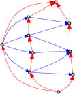
An alternative way to represent a planar graph is to draw the vertices as geometric shapes so that, two shapes touch111We say that two shapes touch if they have a common interval of a positive length. if and only if the corresponding vertices of are adjacent. Such type of representation is called contact representation. Different kinds of shapes for contact representations of planar graph have been considered(eg., [1, 11, 12, 17]). One of the most simple for the visual perception is a contact representation with rectangles. A contact representation with rectangles is called rectangular subdivision, if it forms a partition of a rectangle into a set of smaller non-intersecting rectangles such that no four of them meet at the same point. Such contact representation of a planar graph is known as a rectangular dual of , and is denoted by . Figure 1 shows a planar graph and its rectangular dual. Graph is referred to as primal of . Unfortunately, not all planar graphs admit a rectangular dual. In particular, a planar graph has a rectangular dual with four rectangles on the boundary if and only if every internal face of is a triangle, the external face is a quadrangle and there is no separating triangles in (see eg., [19, Theorem 2.1]). The condition that is bounded by four rectangles can be relaxed [18].
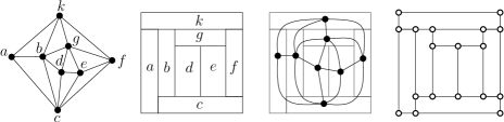
A natural way to simultaneously represent both a planar graph and its rectangular dual is to draw a vertex of inside its corresponding rectangle and to draw each edge as a curve crossing only the common segment of the rectangles representing and (see Figure 1, second from the right). To simplify the visual complexity of such a representation one may ask for a straight-line drawing of . Such a drawing is called straight-line simultaneous drawing of a graph and its rectangular dual . It is not surprising that if the drawing of a rectangular dual is fixed, then it might not be possible to position the vertices of in order to obtain a straight-line simultaneous drawing of and [2, Lemma 1]. It is also known that the corresponding decision problem is -hard [2, Theorem 1]. In this paper, we show that if the rectangular dual is allowed to be resized, i.e. we are allowed to change the sizes of the rectangles (without further changing the structure) we can achieve a straight-line simultaneous drawing of the primal graph and of this resized rectangular dual.
The problem of straight-line simultaneous drawing of a graph and its rectangular dual finds application in visualization of clustered graphs [2, 20]. A rectangular subdivision can be seen as a simplification of a map. Assume that each region of this map contains some elements related to each other (a cluster, and intra-cluster edges) and to the elements of adjacent regions (inter-cluster edges). Some possible readability requirements for a visualization of this network together with the map are that the entire network is drown in a planar fashion, the intra-cluster edges must lie completely inside the corresponding region and the inter-cluster edges must cross only the common segment of the regions where their end-points lie. A simple approach to construct such a visualization is to contract each cluster to a vertex, which results in the graph primal to the given rectangular subdivision. Then, construct a straight-line simultaneous drawing of the primal and the rectangular dual and, finally, uncontract the clusters. This approach is described in detail in [2, Theorem 2].
Allow us, until the end of this section, to reverse the roles of and . In particular, consider the graph , the vertices of which are the corners of the rectangles of and the edges of which are the parts of the sides of the rectangles connecting the vertices (see Figure 1, right). The edges of this graph are represented either by horizontal or by vertical segments, and each face, including the external, forms a rectangle, i.e. implies a so-called rectangular drawing of [22]. Then, graph becomes a week dual222The dual graph of a planar graph with a fixed planar drawing is formed by placing a vertex inside each face of , and connecting vertices of whose corresponding faces in are adjacent. A week dual of the graph results by removing from the vertex representing the external face of . Graph is called the primal of . of this new graph . When asking for a straight-line simultaneous drawing of and we are actually asking for the straight-line simultaneous drawing of the primal and its dual . This point of view helps us to summarize the related work in the next paragraphs.
Drawings of the primal and dual graphs so that each vertex of the dual is placed inside the corresponding face of the primal and each dual edge crosses only the corresponding primal edge will be referred to as simultaneous planar-dual drawing. Such a drawing is called straight-line if both graphs are drawn straight-line. It is immediately clear that in case of a non-week dual a straight-line simultaneous planar-dual drawing does not exist and at least one edge (dual to an external edge) need to have a bend. To avoid this special case from now on we only consider the week dual graph, without further mentioning it.
Already back in 1963 Tutte [24] considered the problem of constructing a straight-line simultaneous planar-dual drawing and showed that it exists when the primal graph is triconnected. The drawing constructed by Tutte’s algorithm may have exponentially large area. Only four decades later, Erten and Kobourov [13] provided a linear-time algorithm to construct a straight-line simultaneous planar-dual drawing on a grid of size for the same family of graphs. Later, Zhang and He [25] improved this result to a grid of size .
Observe that talking about straight-line simultaneous planar-dual drawing, we ask for the construction of the drawings of both the primal and the dual. A stricter variation of the straight-line simultaneous planar-dual drawings was considered by Bern and Gilbert [6], where the drawing of the primal graph is fixed and one only need to determine the positions of dual vertices. Notice that here it is also required that each dual edge crosses only the corresponding primal. Bern and Gilbert observed that the problem is easy if all faces of the primal are triangles, thus the dual vertices can be placed at the meeting points of angle bisectors. They presented a linear time algorithm to construct the drawing of the dual in case where convex quadrilateral faces are also present. They showed that a straight-line drawing of the dual does not always exist if non-convex quadrilaterals are present. Finally, they proved that the decision problem is -hard for five-sided convex faces.
Specially convenient for a discretization method [8] are straight-line simultaneous planar-dual drawings with the additional requirement that the primal and dual edges cross at right-angle. Such drawing always exists if each internal face of the primal graph is a non-obtuse triangle. In particular, the dual graph can be drawn by joining perpendicular bisectors of the edges [5]. The requirement of right-angle crossing in straight-line simultaneous planar-dual drawings have also been studied in [3, 9, 21], see [7] for an overview.
In this paper we show that a given rectangular dual of a planar graph can be resized so that and this resized rectangular dual obtain a simultaneous straight-line drawing. Proof of this statement is the subject of Section 4. Before proving this result we introduce the necessary definitions in Section 2 and give preliminary observations in Section 3.
2 Definitions and useful facts
-digraph and its parts
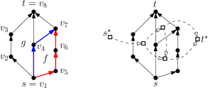
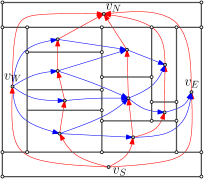
Consider now a directed graph , digraph, for short. A source (resp. a sink) of is a vertex with only outgoing (resp. incoming) edges. An -digraph is an acyclic digraph with exactly one source and exactly one sink . A planar -digraph is an -digraph that is planar and provided with a planar embedding such that vertices and lie on the boundary of the external face(Figure 2, left). It is common to visualize planar -digraphs in an upward fashion, i.e. with edges represented by curves monotonically increasing in upward direction.
It is not hard to see (refer also to [4, Lemma 4.1]) that a face of a planar -digraph is bounded by two directed paths meeting only at the source and at the sink of (see Figure 2, left). If we imagine being embedded upward we can characterize these paths as the left and the right boundaries of . Let be an edge of , the face of lying to the left (resp. right) of is called left (resp. right) face of (see again Figure 2, left).
Topological ordering and dual digraph
A topological ordering of a digraph is a 1-1 function such that for every edge we have (Figure 2, left).
We define the dual digraph of a planar -digraph as follows. The vertex set of is the set of internal faces of plus the two vertices, and , for the external face of , where is for its left and for its right boundary (Figure 2, right). For every edge of , has an edge where and are the left and the right faces of , respectively. Digraph is generally a multigraph, but in this work we merge the multiple edges to one. Digraph is an -digraph with the source the sink [4].
Rectangual dual
Let be a graph. A rectangular dual of is a rectangular subdivision and a one-to-one correspondence between the vertices of and the rectangles of such that two vertices are adjacent in if and only if their corresponding rectangles share a common boundary. If two vertices are adjacent we say that the corresponding rectangles are also adjacent. For the sake of simplicity we use the same notation for the vertices of and for the rectangles of .
Simultanous drawing of a planar graph and its rectangular dual
Let be a graph admitting a rectangular dual . We say that and have a straight-line simultaneous drawing, if we can place each vertex of inside its corresponding rectangle of such that if the edges of are drawn straight-line, the resulting drawing of is planar and each edge crosses only at a single point contained in the common boundary of the rectangles representing and .
Notation and operations for rectangles and rectangular dual
Let be a rectangle on the plane with edges parallel to coordinate axes. We denote by the x- and y-coordinates of the corners of , where and . We denote by the rightmost segment of . Let be a different rectangle adjacent to . We denote by the maximal common segment of and . If segment is vertical, we denote by , the y-coordinates of its end-points. We say that and have vertical (resp. horizontal) adjacency if the segment is vertical (resp. horizontal).
Given a rectangle on the plane, we define as stretch of as the increase of . Let be a rectangular dual of a planar graph . We define a scaling of to be a rectangular dual of that results from resizing of some of the rectangles of . Observe that scaling does not change the type of the adjacency(vertical or horizontal) of two adjacent rectangles of .
Visibility
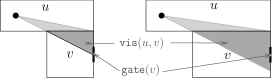
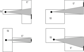
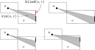
Our target is to construct a straight-line simultaneous drawing of a planar graph and its rectanglular dual . When we place vertex inside its corresponding rectangle in we denote by , the coordinates of . Our main requirement is that an edge of crosses the boundaries of the rectangles of only at a single point and particularly it only crosses the segment . To work with this requirement, we need several additional definitions which reflect the notion of visibility of a vertex inside a rectangle to an adjacent rectangle. Let and be two adjacent vertices of , and assume that the position of vertex in its corresponding rectangle of is fixed. The visibility region of inside , denoted by , is the region delimited by the boundary of the rectangle and the lines through and the two end-points of the segment , see for example Figure 3 and Figure 4. If and have horizontal adjacency such that is above and , then contains the topmost segment of (Figure 3). In case and have vertical adjacency we distinguish two types of visibility region as follows. We say that the visibility region is diverging and that is a diverging neighbor of if the two lines through delimiting have slopes of a different sing. Figure 4, depicts several cases of diverging visibility regions. Figure 5, top left, depicts non-diverging visibility regions.
Assume again that and have a vertical adjacency and is to the left of . In case is a non-diverging neighbor of we have that either or . See Figure 5, top left for the illustration of the case . Consider the set , it is non-empty and generally contains two segments; one containing the topmost point of and one containing the botommost point of . We denote by the segment of which contains the topmost (resp. bottommost) point of for the case (resp. ) (Figure 5, top left).
During the construction of the straight-line simultaneous drawing of and its rectangular dual we mostly place vertices close to the right boundary of the rectangles. To formalize this we use the following notation. Let be a rectangle, we denote by a proper sub-interval of not containing both end-points of .
Regular edge labeling
Let be a planar embedded planar graph with no separating triangle, with exactly four vertices on the external face and each internal face being a triangle. It is known that such a graph has a rectangular dual (see e.g. [18]). Two adjacent rectangles of have either vertical or horizontal adjacency. This fact is mirrored by so-called regular edge labeling (REL, for short) [18], defined for graph , which is also known as transversal structure [15]. It is formally defined as follows. A REL of is a partition and orientation of its interior edges resulting in two disjoint sets of arcs and , so that:
-
•
For each internal vertex the edges incident two appear in the counterclockwise order as follows: edges in outgoing from , edges in incomming to , edges in incomming to , and edges in outgoing from ; moreover, none of these four sets of edges is empty;
-
•
Four outer vertices of are named , , , and . Moreover, the internal edges incident to (resp. ) are all in and are outgoing from (resp. incomming to ). Also, the internal edges incident to (resp. ) are all in and are outgoing from (resp. incomming to ).
It is known that every planar graph without separating triangles, with exactly four vertices on the outer face and each internal face being a triangle has a REL [18, Theorem 2.2]. Such a REL is used as a tool for constructing a rectangular dual of . Let (resp. ) be the directed subgraph of induced by the edges in (resp. ) and the four exterior edges directed such that (resp. ) is a source of (reps. ) and (resp. ) is a sink of (reps. ). We will heavily rely on the fact that is a planar -digraph with source and sink [18, Lemma 2.3]. We use red and blue colors to distinguish edges in and .
Observe that given a rectangular dual of , one can construct a REL by: placing internal edges of depicting horizontal adjacency to and orienting them from bottom to top, and placing internal edges depicting vertical adjacency to and orienting them from left to right. This REL is said to be defined by the rectangular dual . The reverse is also true, given a REL of one can construct a rectangular dual such that the blue edges specify vertical and the red edges horizontal adjacency [18, Theorem 4.3]. This is said to be consistent with the given REL.
3 On visibility between two adjacent rectangles
The following statement is illustrated in Figure 3.
Statement 1
Let and be two horizontally adjacent rectangles, such that is above , and . There exists such that, , if we set then .
Proof
The statement follows from the facts that the region contains the upper part of and the lower half-line delimiting the region has a negative slope.
Statement 2
Let and be two vertically adjacent rectangles, such that is to the left of and is a diverging neighbor of . There exists such that, , if we set then the .
Proof
The four cases determined by possible relations among the coordinates , , and are shown on Figure 4. Since the region is diverging, i.e. the half-lines through delimiting have positive and negative slope, there exists , such that, for any , if we set , then and therefore .
Statement 3
Let and be two vertically adjacent rectangles, such that is to the left of and ( is a non-diverging neighbor of ). If then there exists such that, , if we set then . Otherwise, there exists such that if we set then .
Proof
Assume first that (see Figure 5, top left) for the illustration. Since both lines delimiting have negative slope, as grows “slides” over from bottom to top. Thus, there exists such that, , if we set then (Figure 5, top right).
Assume now that (Figure 5, bottom left). Observe that as increases and remains less than , the slope of the topmost half-line delimiting increases and remains negative. Thus, if , then the mentioned half-line has slope zero and . So, when tends to , tends to . Recall that is the topmost segment of , and that does not contain the topmost point of . Hence, there exists when is small enough and does not intersect with (Figure 5, bottom right).
The following statement is symmetric to Statement 3 and can be proven identically.
Statement 4
Let and be two vertically adjacent rectangles, is to the left of and ( is a non-diverging neighbor of ). If then there exists such that, , if we set then the . Otherwise, there exists such that if we set then .
4 Main result
Theorem 4.1
Let be a planar graph admitting a rectangular dual . There exists a scaling of such that and admit a straight-line simultaneous drawing.
Proof
We assume that is bounded by four rectangles (see Figure 6) that have horizontal adjacency between each other, if not so we add them to , as well as the corresponding vertices to . For the simplicity of notation we denote the new graph by and its rectangular dual by . After the scaling of is created and the straight-line simultaneous drawing of and is constructed we simply remove the added vertices and rectangles. We denote the bottomost rectangle of by , the topmost by , the leftmost by and the rightmost by .
Let be the edge set of and let be the REL of that is defined by rectangular dual (refer to Figure 6). Recall that is the subgraph of containing only the edges of plus the four external edges that are oriented so that is a source and is a sink. Recall also that is an -digraph.
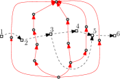
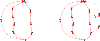
Let be the dual of , it is an -digraph by itself. Let be a topological ordering of the vertices of (see Figure 7). We denote by , the subgraph of constituted by the vertices and edges of the faces (Figure 8, left). As a special case, graph is the subgraph containing only vertices and the edges . While . It is not difficult to see that is an -digraph and that can be constructed from by adding the right boundary of to the external face of (see Figure 8). This fact is proven formally in [16, Lemma 4] for maximal planar -digraphs, the proof for non-maximal planar -digraph is along the same lines. Let be the subgraph of that is induced by the vertices of (see Figure 9). Observe that the edges of that do not belong to are blue and lie in the internal faces of .
In the following, by induction on , , we construct a rectangular dual of consistent with the REL (restricted to ), and show how to construct a straight-line simultaneous drawing of and . For we will obtain a rectangular dual of and the straight-line simultaneous drawing of and . Since is consistent with the REL it represents a scaling of . So the theorem will follow.
- Base case: .
-
consists of the vertices , , . The graph contains only the red edges and . We represent the three vertices , , of as three rectangles such that , and (see Figure 10). Graph contains exactly the same edges as and a straight-line simultaneous drawing of and can be constructed trivially.
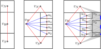
Figure 10: Left: the base case. Middle and right: induction step illustrated on the graph of Figure 6. Before induction step we have simultaneous drawing of and (middle). After induction step we have simultaneous drawing of and (Figure 13). Intermediate steps are also shown in Figure 11. Middle: rectangles appear on the right boundary of . Right: placement the rectangles . The light grey regions show the visibility of inside . The dark grey regions show the intersection of visibility regions of all neighbors. - Induction hypothesis.
-
For each , there exists a rectangular dual of consistent with such that and have a straight-line simultaneous drawing.
- Induction step.
-
As mentioned above, can be constructed from by adding the right boundary of to the external face of . Let directed path be the left boundary of . Since vertices represent a directed sub-path of the right boundary of the external face of , the rectangles appear on the right boundary of and lie on top of each other. See Figure 10 for a specific example. Let be the right boundary of . We stretch all the rectangles of the right boundary of except for by the same value (Figure 10, right) and place the new rectangles vertically between and , according to the adjacency between the vertices and . We set , thus the current is bounded by a rectangle and obviously comprises a rectangular dual of , consistent with REL .
Consider those of rectangles (resp. vertices) that are adjacent to at least two rectangles (resp. vertices) among , we call them critical. We next show that the rectangles of the right boundary of can be resized so that the gate of each critical rectangle is in the visibility region of each of its neighbor. The resizing consists of two modifications; we first stretch the right boundary of , which ensures visibility to the gates of some of the critical vertices, and fulfillment of a special condition for the gates of the remaining critical vertices. We then obtain visibility to the gates of these remaining critical vertices by moving vertically some common boundaries of , such that the existing visibilities are preserved. We do not perform any operation for non-critical vertices. Their placement is simple and will be explained at the end of the construction.
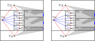
Figure 11: Left: After the horizontal stretch of the right boundary of , where the initial is shown in Figure 10, right. The value of the stretch is determined by the pairs and . For the pair (resp. ) Statement 1 (resp. Statement 2) is applied, to achieve that (resp. ). Finally, Statement 4 applies for the pair , to archive that . The remaining adjacencies does not increase the value of the stretch. Right: Statement 4 is applied to the pair to archive that and as a result the common boundary is moved down. We first further specify the positions of the gates of those of which are critical. See Figure 12, left for the illustration. Consider a critical vertex , , and let be the minimum index and be the maximum index such that and and are adjacent to . Positions of the vertices and are known by induction hypothesis. We place so that . The reason for this positioning of the gates for the critical vertices will become clear later in the proof. The gates of the non-critical vertices are not of any interest to us, since they will not be used.
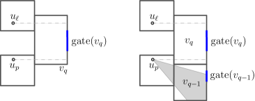
Figure 12: Left: Illustration for the placement of gates of the critical vertices. Right: After second modification it holds that . Consider a , , and its neighbor, say , . If is a diverging neighbor of then Statement 2 applies and determines the value , such that , if we set then . If is a non-diverging neighbor of , but then Statement 3 or Statement 4 determine the value , such that , if we set then . Finally, the values and are determined by Statement 1. Let .
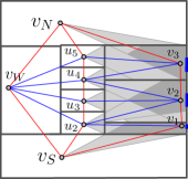
Figure 13: Statement 4 is applied to the pair to archive that and as a result the common boundary is moved down. We now stretch the right boundary of to have coordinate (refer to Figure 11, left). By Statement 2, if , , is a diverging neighbor of , ,then .
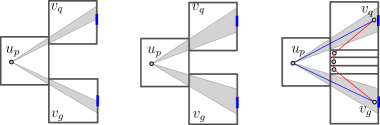
Figure 14: Illustration of the second modification, where the common horizontal boundaries of are possibly moved. Left: Vertex is a non-diverging neighbour of and , it holds that and . Middle: Statement 3 is applied to and . Statement 4 is applied to and . Right: the non-critical neighbors of are placed and the vertices of are positioned as explained in the proof. Let now , , be a vertex with non-diverging neighbor , . The previous modification ensures that . By Statements 3 and 4, the exists (case ) or (case ) such that if we set then (refer to Figure 11, right and to Figure 13 for the specific example, refer also to Figure 14 for an abstract example).
In the following we show that the second modification does now destroy the visibilities to the critical vertices which existed after the first modification. First, observe that after the second modification the , of a critical vertex still belongs to . This is ensured by the initial placement of the gates of the critical vertices. Thus, consider Figure 12 (right), where is a non-diverging neighbor of . The result of the second modification will be that the common boundary is moved up to . By the placement of the we have that and therefore . By a symmetric argument for , and we infer that .
Second, assume that a vertex is a non-diverging neighbor of such that and such that (Figure 14), then the application of Statement 3 results in moving the segment down to a -coordinate . The last inequality ensures that the visibility of inside has not changed.
We now explain how to draw the non-critical vertices, consider again Figure 14. Assume that is a non-diverging neighbour of , such that and , such that . As already mentioned, the application of Statement 3 results in moving the segment down to a -coordinate . The application of Statement 4 results in moving up to . Thus, and the space between and is used for the placement of the non-critical neighbors of (see Figure 14, right). It may happen that , then we set .
Next, we place the actual vertices of the right boundary of , except of and , which have already been placed by induction hypothesis. For each critical vertex we place vertex very close to the middle of . Since for each neighbor of , the straight-line edge crosses only . A non-critical vertex , which is adjacent to a single vertex , is placed arbitrarily close to the common segment . Thus, the straight-line edge crosses only . Edges and cross the segments and , respectively, as ensured by the application of Statement 1. Finally, each edge , , crosses only , since and . This concludes the proof of the theorem. ∎
5 Conclusion
In this paper we considered the problem of drawing simultaneously a planar graph and its rectangular dual. We required that the vertices of the primal are positioned in the corresponding rectangles, the drawing of the primal graph is planar and straight-line, and each edge of the primal crosses only the rectangles where its end-points lie. Our proof in constructive and leads to a linear-time algorithm. However, the vertices are not placed on the grid and the area requirements of the construction are unclear. It would be interesting to either refine the algorithm to produce a simultaneous drawing with polynomial area, or to construct a counterexample, requiring an exponential area.
Acknowledgments
I would like to thank Md. Jawaherul Alam, Michael Kaufmann, Stephen Kobourov and Roman Prutkin for the useful discussions during the preliminary stage of this work.
References
- [1] Md. Jawaherul Alam, Therese C. Biedl, Stefan Felsner, Michael Kaufmann, and Stephen G. Kobourov. Proportional contact representations of planar graphs. J. Graph Algorithms Appl., 16(3):701–728, 2012.
- [2] Md. Jawaherul Alam, Michael Kaufmann, Stephen G. Kobourov, and Tamara Mchedlidze. Fitting planar graphs on planar maps. In Viliam Geffert, Bart Preneel, Branislav Rovan, Julius Stuller, and A Min Tjoa, editors, SOFSEM 2014: Theory and Practice of Computer Science - 40th International Conference on Current Trends in Theory and Practice of Computer Science, Nový Smokovec, Slovakia, January 26-29, 2014, Proceedings, volume 8327 of Lecture Notes in Computer Science, pages 52–64. Springer, 2014.
- [3] Evmorfia N. Argyriou, Michael A. Bekos, Michael Kaufmann, and Antonios Symvonis. Geometric RAC simultaneous drawings of graphs. J. Graph Algorithms Appl., 17(1):11–34, 2013.
- [4] Giuseppe Di Battista, Peter Eades, Roberto Tamassia, and Ioannis G. Tollis. Graph Drawing: Algorithms for the Visualization of Graphs. Prentice Hall PTR, Upper Saddle River, NJ, USA, 1st edition, 1998.
- [5] Marshall Bern and David Eppstein. Polynomial-size nonobtuse triangulation of polygons. International Journal on Computational Geometry and Applications, 2:241 – 255, 1992.
- [6] Marshall Bern and John R. Gilbert. Drawing the planar dual. Information Processing Letters, 43(1):7 – 13, 1992.
- [7] Thomas Bläsius, Stephen G. Kobourov, and Ignaz Rutter. Simultaneous embedding of planar graphs. In Roberto Tamassia, editor, Handbook of Graph Drawing and Visualization, pages 349–381. CRC Press, 2013.
- [8] Eric Grosse Brenda S. Baker and Condor S. Rafferty. Nonobtuse triangulations of polygons. Discrete Computational Geomentry, 3:147 – 168, 1988.
- [9] Graham R. Brightwell and Edward R. Scheinerman. Representations of planar graphs. SIAM J. Discret. Math., 6(2):214–229, 1993.
- [10] H. de Fraysseix, J. Pach, and R. Pollack. How to draw a planar graph on a grid. Combinatorica, 10(1):41–51, 1990.
- [11] Hubert de Fraysseix, Patrice Ossona de Mendez, and Pierre Rosenstiehl. On triangle contact graphs. Combinatorics, Probability & Computing, 3:233–246, 1994.
- [12] Christian A. Duncan, Emden R. Gansner, Yifan Hu, Michael Kaufmann, and Stephen G. Kobourov. Optimal polygonal representation of planar graphs. Algorithmica, 63(3):672–691, 2012.
- [13] Cesim Erten and Stephen G. Kobourov. Simultaneous embedding of a planar graph and its dual on the grid. Theory Comput. Syst., 38(3):313–327, 2005.
- [14] I. F’ary. On straight lines representation of planar graphs. Acta Scientiarum Mathematicarum, 11:229––233, 1948.
- [15] Éric Fusy. Transversal structures on triangulations: A combinatorial study and straight-line drawings. Discrete Mathematics, 309(7):1870–1894, 2009.
- [16] Francesco Giordano, Giuseppe Liotta, Tamara Mchedlidze, Antonios Symvonis, and Sue Whitesides. Computing upward topological book embeddings of upward planar digraphs. J. Discrete Algorithms, 30:45–69, 2015.
- [17] Daniel Gonçalves, Benjamin Lévêque, and Alexandre Pinlou. Triangle contact representations and duality. Discrete & Computational Geometry, 48(1):239–254, 2012.
- [18] Xin He. On finding the rectangular duals of planar triangular graphs. SIAM J. Comput., 22(6):1218–1226, 1993.
- [19] Xin He. On floor-plan of plane graphs. SIAM Journal of Computing, 28(6):2150–2167, 1999.
- [20] Yifan Hu, Emden R. Gansner, and Stephen G. Kobourov. Visualizing graphs and clusters as maps. IEEE Computer Graphics and Applications, 30(6):54–66, 2010.
- [21] Bojan Mohar. Circle packings of maps in polynomial time. European Journal of Combinatorics, 18(7):785 – 805, 1997.
- [22] Takao Nishizeki and Md. Saidur Rahman. Rectangular drawing algorithms. In Roberto Tamassia, editor, Handbook of Graph Drawing and Visualization, pages 317–348. CRC Press, 2013.
- [23] W. Schnyder. Embedding planar graphs on the grid. In Proceedings of the 1st ACM–SIAM Symposium on Discrete Algorithms (SODA), pages 138––148, 1990.
- [24] WilliamThomas Tutte. How to draw a graph. In Proceedings of the London Mathematical Society, volume 13, pages 743––768, 1963.
- [25] Huaming Zhang and Xin He. On simultaneous straight-line grid embedding of a planar graph and its dual. Information Processing Letters, 99(1):1 – 6, 2006.