Controlled generation of higher-order Poincaré sphere beams from a laser
Abstract
The angular momentum state of light can be described by positions on a higher-order Poincaré (HOP) sphere, where superpositions of spin and orbital angular momentum states give rise to laser beams that have found many applications, including optical communication, quantum information processing, microscopy, optical trapping and tweezing and materials processing. Many techniques exist to create such beams but none to date allow their creation at the source. Here we report on a new class of laser that is able to generate all states on the HOP sphere. We exploit geometric phase control with a non-homogenous polarization optic and a wave-plate inside a laser cavity to map spin angular momentum (SAM) to orbital angular momentum (OAM). Rotation of these two elements provides the necessary degrees of freedom to traverse the entire HOP sphere. As a result, we are able to demonstrate that the OAM degeneracy of a standard laser cavity may be broken, producing pure OAM modes as the output, and that generalized vector vortex beams may be created from the same laser, for example, radially and azimuthally polarized laser beams. It is noteworthy that all other aspects of the laser cavity follow a standard design, facilitating easy implementation.
pacs:
Introduction
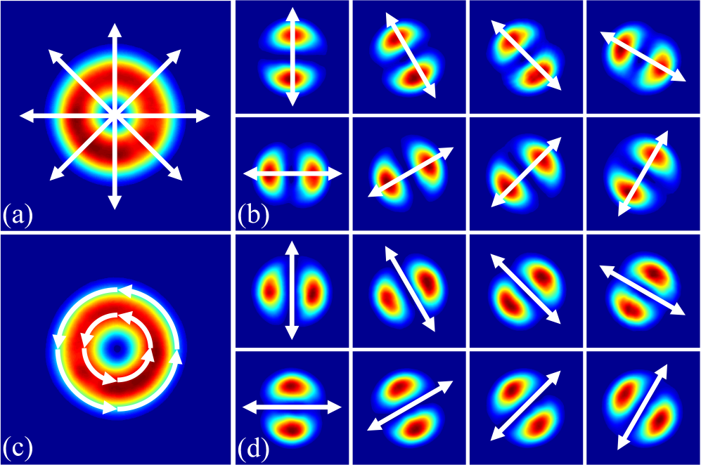
Recently the concept of the Higher-Order Poincaré (HOP) sphere was introduced as a theoretical framework for describing the total angular momentum of light, both spin and angular components Milione2011 ; Milione2012 ; Holleczek2011 . The HOP sphere describes higher-order states of polarization of generalized vector vortex beams, as shown in Fig. 1 (a), in contrast to the Poincaré sphere (PS) which is a geometric representation of all possible states of polarization. While the Poincaré sphere is a Bloch sphere where the basis states are two orthogonal states of polarization, the HOP sphere is a Bloch sphere where the basis states are more general orthogonal states that incorporate both SAM and OAM.
All the optical modes on the HOP sphere have an intensity distribution with a central null, as shown in Fig. 1 (b). These states may be differentiated by the transmitted intensity through a linear polarizer, e.g., vertically orientated as depicted by the double sided arrows. Light fields described by points on the HOP sphere are prevalent in nature and have found applications in high-speed kinematic sensing Berg2015 , OAM fiber mode selection Gregg2015 , space division multiplexing Lavery2014 and mode division multiplexing Milione2015 . In particular it is worth calling the attention of the reader to the poles and the equator of the sphere. The equator represents the cylindrical vector (CV) beams Zhan2009 , with special cases being the azimuthally and radially polarized light fields as shown in Fig.1 (b). These fields have found many applications, for example, in laser material processing Nesterov2000 ; Meier2007 ; Venkatakrishnan2012 , particle acceleration Tidwell1993 ; Gupta2007 ; Wong2010 ; Dai2011 , optical trapping Kozawa2010 ; Huang2012 ; Donato2012 ; Loke2014 and microscopy Hao2010 ; Chen2013 . The extra-cavity generation of such beams has been achieved by using an interference approach Tidwell1990 ; Tidwell1993 ; Passilly2005 , liquid crystals Ren2006 ; Bashkansky2010 , sub-wavelength grating Machavariani2007 and from a spirally varying retarder Lai2008 . Laser cavities have been customized to produce particular CV beams by techniques such as inducing thermal stress to isotropic gain media Moshe2003 , by exploiting the thermal birefringence of laser gain media Yonezawa2006 ; Kawauchi2008 ; Ito2009 , with the use of an intra-cavity axicon Kozawa2005 ; Bisson2006 ; Chang2013 and with a conical shaped pump beam Wei2013 ; Vyas2014 ; Fang2015 .
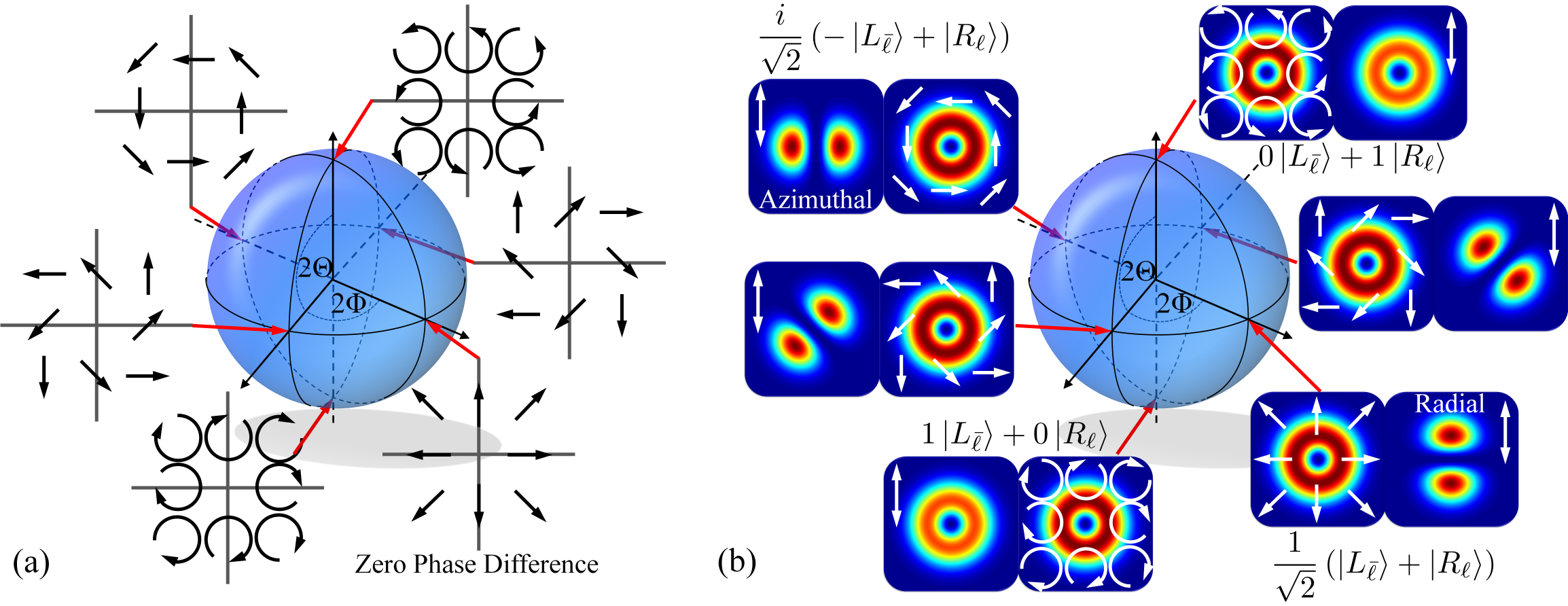
The poles of the HOP sphere represent scalar vortex beams (having helical wavefronts) with a uniform circular polarization (right circular at the north pole and left circular at the south pole). The helicity of the wavefront arises from the azimuthally varying phase structure of and such beams carry orbital angular momentum (OAM) of per photon where is referred to as the topological charge and can take any integer value. Henceforth we will refer to the sign of the helicity (the sign of ) as the “handedness” of the light. Such beams have found many applications in diverse fields such as optical manipulation Grier2003 ; Padgett2011 , and optical free space communication Wang2012 . While many attempts have been made to generate these modes inside a laser cavity Senatsky2012 ; Lin2014 ; Kim2015 ; Lin2015 ; Litvin2014 the degeneracy in the handedness of the azimuthal modes means that standard laser cavities cannot distinguish them: the spatial intensity distribution of laser modes with opposite azimuthal handedness (such as and ) are identical, they have identical radii of curvature on the wavefront and identical Gouy phase shifts. Consequently their intra-cavity losses are identical and thus very often uncontrolled helicities, coherent, or incoherent superpositions of modes with opposite handedness are produced Litvin2014 . Thus while customized lasers have demonstrated specific points on the HOP sphere, each point requiring its own laser design, no laser to date has been able to create an arbitrary HOP sphere beam.
Here we show the generation of any HOP sphere beam directly from a laser. We couple SAM to OAM inside the laser cavity by means of a wave-plate and a non-homogeneous polarisation optic (-plate) so that polarization control maps to OAM mode control. This is the first time that Pancharatnam-Berry (geometric) phase control has been applied inside a laser for mode selection. By control of the relative angles between the wave-plate and -plate we can adjust the geometric phase change of the circulating light, and use this to produce any arbitrary beam on the HOP sphere, including the special cases of cylidrical vector vortex beams, e.g., azimuthally and radially polarised light, as well as pure OAM modes. We outline the theory for the mode control and confirm it experimentally in a solid state laser for HOP sphere beams of azimuthal orders and .
Concept and Theory
In contrast to the complexity and challenges of producing OAM beams and vector vortex beams from lasers, the control of polarization, or spin angular momentum (SAM), inside laser cavities is a well established technique Hodgson2005 . Our central idea is to exploit the SAM control as a proxy for OAM control, thereby realising generalized modes on the HOP sphere.
Consider a standard solid-state laser cavity in a Fabry-Pérot configuration, as shown in Fig. 2 (a). Inclusion of a polarising beam splitter (PBS) and quarterwave-plate (QWP) ensure that the polarisation state in region A is always linearly polarised, the orientation dependent on that of the PBS. Traditionally such cavities are used to output light from the PBS, with the orientation of the QWP acting as a control on the fraction of light leaked out. It follows that in region B the circulating light is circularly polarised. In such a cavity the polarisation at any position is controlled and repeated after every round trip.
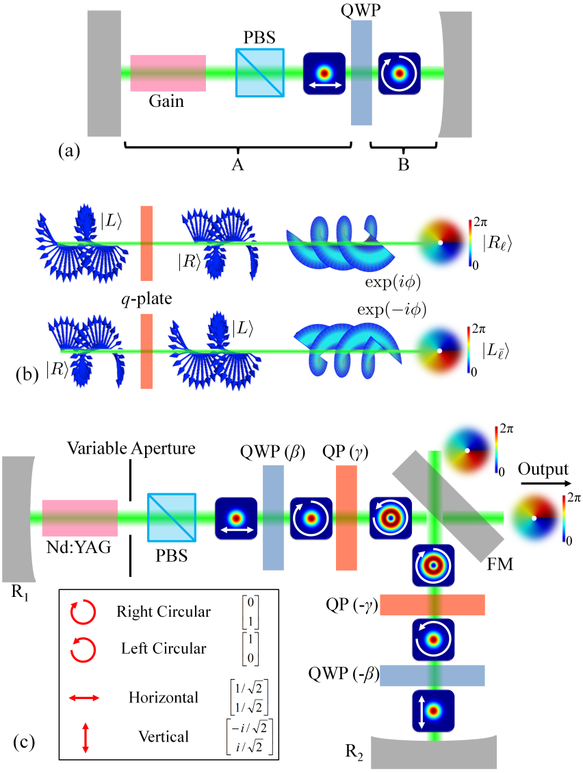
We introduce a non-homogenous polarisation optic, in the form of a -plate Marucci2006 , into the cavity to act as a SAM to OAM converter. The -plate ladders some incoming OAM state following the selection rules: and , where and refer to left and right circularly polarised light, is the incoming OAM state and is the charge of the -plate (see Supplementary Material). This concept is illustrated graphically in Fig. 2 (b). By modifying the standard cavity to that shown in Fig. 2 (c), OAM-carrying beams are created within the cavity. The doubling of the elements ensures that the spatial mode and polarisation states are repeated after each complete round trip. The QWP and -plate angles provides two degrees of freedom necessary to traverse the entire HOP sphere. It can be shown (see Supplementary Material) that our repeating mode in the cavity can be described by
| (1) |
where , , with and representing uniform left circular and right circular polarization states, respectively, and where and are the rotation angles of the QWP and q-plate, respectively. This is precisely the description of a point on the HOP sphere with coordinates and , where the poles on the sphere represent the basis states and . In other words, any HOP sphere beam can be realised from the laser. Examples of special cases are given in Table 1.
| 0 | ||
|---|---|---|
Heuristically the cavity can be understood by following the evolution of a Gaussian mode of linear polarisation propagating in region A away from mirror . The horizontally polarised Gaussian beam is converted into a left circularly polarised Gaussian beam after the wave-plate if the wave-plate axis is at . The -plate converts this left circularly polarised beam into an OAM beam of charge with right circular polarization. Reflection off the mirror inverts the entire state in both SAM and OAM, while the two remaining elements, orientated at opposite angles to the first two, reverse the process to create a vertically polarised Gaussian beam incident on mirror . When this beam is propagated backwards through the cavity the modes invert again and return to mirror to the starting mode. The consequence is that the handedness of the light, as well as its vector nature, is completely defined by the angles of the QWP () and -plate (). For example, if the QWP is rotated to produce linearly polarized light prior to the -plate, then superpositions of left and right handed light with opposite OAM charges is produced - our general vector beams.
Experiment
The resonator concept as illustrated in Fig. 2 (c) necessitates the use of a pair of -plates and a pair of QWPs with a polarization insensitive mirror (FM) positioned between the -plates. This cavity may be equivalently constructed by resorting to a V-shaped cavity where the two arms are separated within a few degrees with a planar mirror positioned at the apex of the V allowing for an off-axis design where only a single -plate and QWP are required. The V-shaped cavity was experimentally realised in a diode-pumped solid-state laser where a 0.5 at.- Nd-doped YAG rod (4 50 mm rod) was side pumped with a total input average pump power of W operating at 805 nm. The end mirrors were both concave high reflectors with curvatures mm and mm, respectively, with a planar mirror of 90 reflectivity positioned at the apex of the V. The separation distance between the two concave mirrors was 900 mm and the angle at which the two arms were separated by the plane mirror was in the order of 5∘. The -plate () was designed to operate most efficiently when positioned on-axis and it was thus positioned sufficiently adjacent to the plane mirror. The QWP (Multi-order operating at 1064 nm) was required to transmit both arms and was thus positioned to incorporate its clear aperture of mm. A lens of focal length mm was inserted in the cavity to aid stability and to facilitate the clear aperture restriction imposed by the QWP. Finally a polarizing beam splitter (PBS) was preferred for the selection of linear polarization in the horizontal. A further practical consideration was required to be met in that with the pump arrangement, multimode operation was favoured which allows the existence of higher-order azimuthal and radial modes, we thus inserted a circular aperture with variable diameter such that the field incident on the -plate was LG00 in shape, i.e., only radial indices of were allowed. The forward propagating wave with this arrangement was considered as the propagation from to with the back propagating wave acting in reverse. These two waves impinged on the planar mirror thus presenting two outputs; however, our interest lies in the output of the forward wave, as described by Eq. 1.
Results
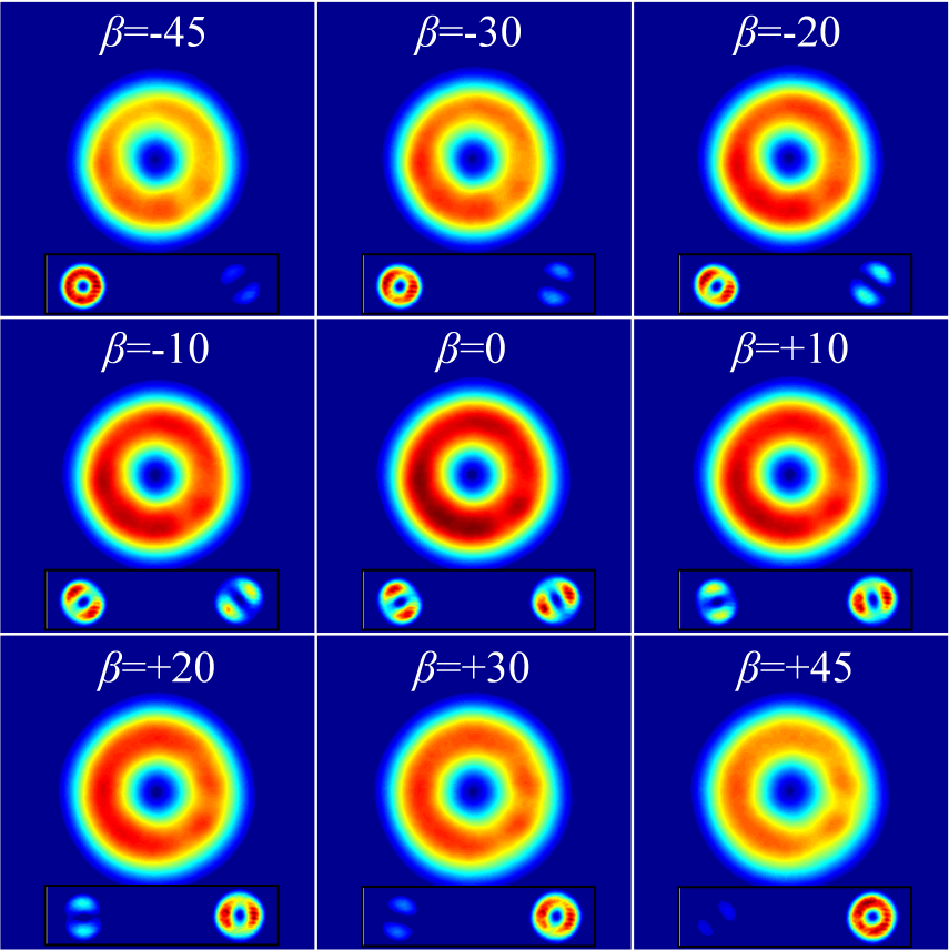
We initially set and varied the angle of rotation, , of the QWP. The output beam was an annular shaped beam (see Fig. 3) independent of , as expected from theory. The state of the output is given by where and are the relative weightings of the states on the poles. A measurement of the polarisation state (evident from the inserts in Fig. 3) confirms that the mode evolves from a left-circularly polarized beam () to a right-circularly polarized beam ().
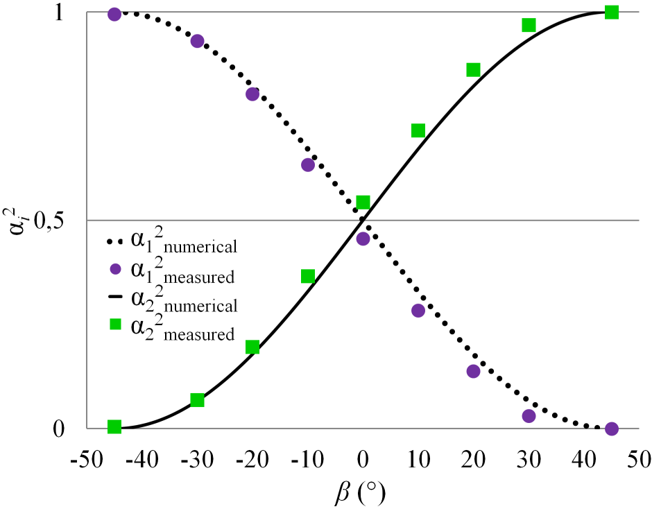
To determine the accuracy in the variation of the polarization as shown in Fig. 3, we measured the intensity of the relative weightings of the left and right components of the transmitted light. These components describe the states on the poles of the HOP sphere and thus and . The measured intensities of the respective components compare well with the numerical determination for varied from to as illustrated in Fig. 4.
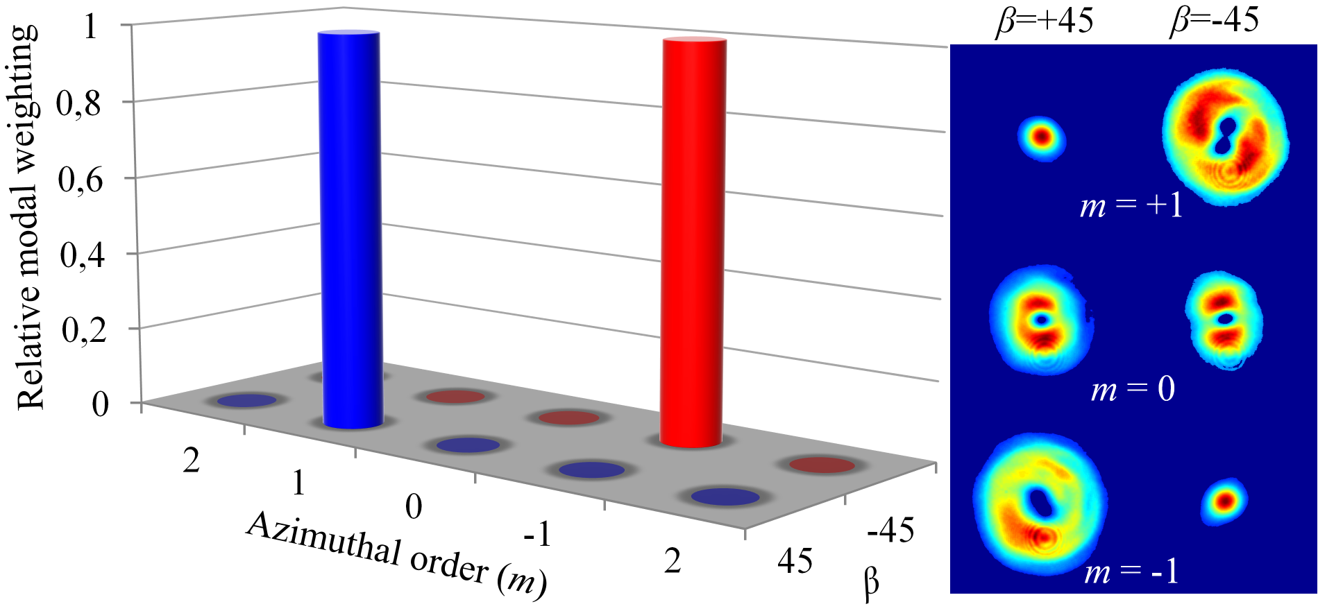
Next we measured the OAM state by an azimuthal inner product Flamm2012 ; Naidoo2012 with a phase-only spatial light modulator (see Supplementary Material). We find that at the mode is a pure helicity, while a pure for . This is illustrated graphically in Fig. 5, together with the raw data for three of the modal decomposition channels, where a central peak indicates the present mode, and a central null indicates the absence of that mode. The intra-cavity aperture ensures that the radial index of the mode is , and this too is confirmed by modal decomposition (see Supplementary Material). This approach presents a means to actively select the handedness of pure LG0±ℓ modes depending only on the rotation angle of the QWP and the charge of the -plate.
Modes represented on the equator of a HOP sphere consist of a mixture of SAM and OAM states as determined by Eq. (1). The combination of SAM states is achieved by setting to zero such that a pure linear state is incident on the -plate resulting in a superposition output (as in the insert of Fig. 3 for ). Consequently this also leads to a superposition of OAM and SAM states at the output, as given in Table 1. The non-separability of the polarization and spatial content of the mode means that upon passing through a linear polarizer, the annular shaped output splits into two lobes that rotate with a rotation in the polarizer.
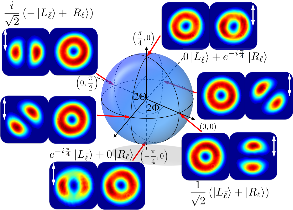
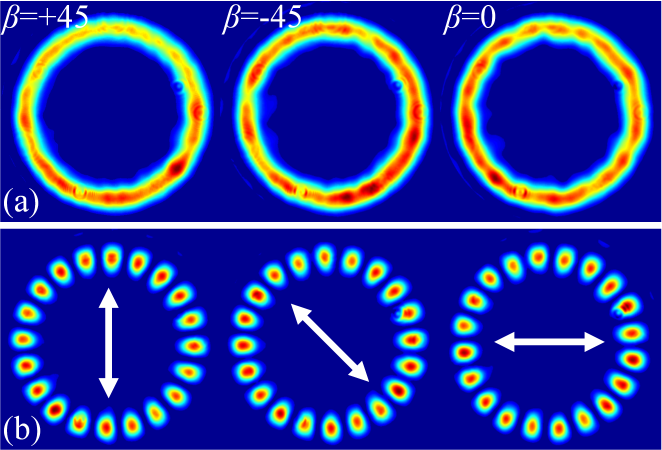
With the laser operating under the conditions of and , we obtain an annular shaped (Fig. 6 (a)) beam that leads to a rotatable lobed beam (Fig. 6 (b)) succeeding a linear polarizer. The two lobed structure is oriented parallel to the orientation of the linear polarizer (illustrated as double sided arrows) thus presenting a pure radially polarized vectorial vortex beam. With rotated by we select an annular shaped beam (Fig. 6 (c)) that is of pure azimuthal polarization which is hallmarked by the two lobed structure being perpendicular to the orientation of the linear polarizer (Fig. 6 (d)). The remarkable nature of selectively exciting these vectorial vortex beams is that not only are cylindrical vector-vortex beams achievable but so too are arbitrary vector states by controlling the input polarization state on the -plate by adequately selecting the rotation angle . An astute control of and allows for the entire HOP sphere to be mapped and to aid consistency in comparison to Fig. 1 (b), the states between the radial and azimuthal polarizations are accordingly determined as illustrated in Fig. 7. The annular outputs are transmitted through a linear polarizer oriented in the vertical (depicted by the double sided arrows) and are in excellent agreement with the anticipated intensities.
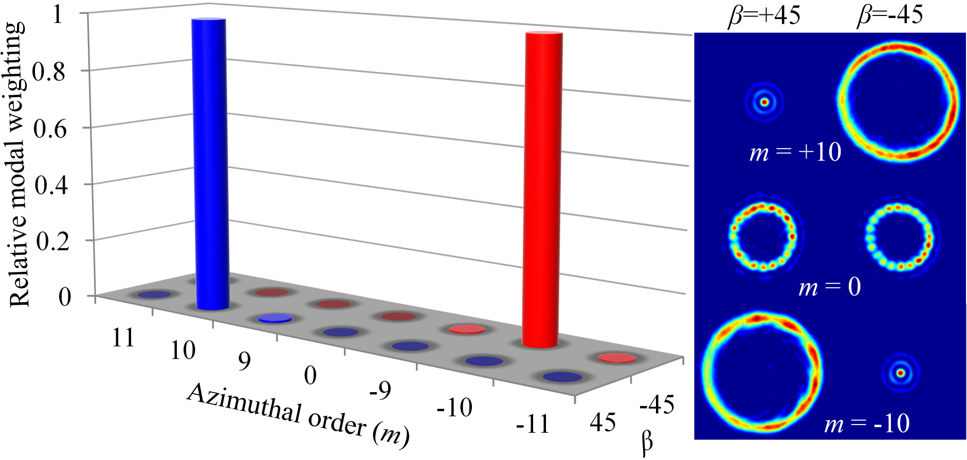
This technique is not limited to LG0,±1 modes, in fact a -plate with a higher value may be equivalently realised. We demonstrate this by replacing the -plate of with thus allowing for the selection of LG0,±10 modes without changing the physical properties of the cavity. The outputs for the cavity operating under , and with are illustrated in Fig. 8 (a) and show well defined annular beams. With the cavity operated at , the annular output leads to a rotatable lobed beam succeeding a linear polarizer as shown in Fig. 8 (b) resulting in a radially polarized output. Again, to infer the OAM of the mode, we execute an azimuthal inner product with the digitally encoded transmission function for varying from -12 to +12 in unit steps and we identify an on-axis signal for and with zero elsewhere corresponding to operation for and , respectively as presented in Fig. 9 with some example measurement channels.
Conclusion
We have outlined the concept for a new class of laser that utilised geometric phase control to realise arbitrary HOP sphere beams. We have demonstrated the concept in an otherwise conventional solid state laser cavity and shown the controlled generation of such beams, including the special cases of pure OAM modes as well as azimuthally and radially polarised light. As these fields have found many applications to date, we envisage that the versatility of creating HOP sphere beams directly from the source will find much interest. In particular, as the first example of intra-cavity mode selection by the Pancharatnam-Berry phase, we believe this report will spurn interest in this approach to designing custom lasers.
References
- (1) G. Milione, H. I. Sztul, D. A. Nolan, R. R. Alfano, Phys. Rev. Lett. 107, 053601 (2011).
- (2) G. Milione, S. Evans, D. A. Nolan, R. R. Alfano, Phys. Rev. Lett. 108, 190401 (2012).
- (3) A. Holleczek, A. Aiello, C. Gabriel, C. Marquardt, G. Leuchs, Opt. Exp. 19, 9714 (2011).
- (4) S. Berg-Johansen, et al., arXiv:1504.00697v1 (2015).
- (5) P. Gregg, et al., Opt. Lett. 40, 1729 (2015).
- (6) M. P. J. Lavery, et al., Proc. ECOC We.3.6.1 (2014).
- (7) G. Milione, et al., Opt. Lett. 40, 1980 (2015).
- (8) Q. Zhan, Adv. Opt. Photon. 1, 1 (2009).
- (9) A. V. Nesterov, V. G. Niziev, J. Phys. D 33, 1817 (2000).
- (10) M. Meier, V. Romano, T. Feurer, Appl. Phys. A 86, 329 (2007).
- (11) K. Venkatakrishnan, B. Tan, J. Laser Micro/NanoEng. 7, 274 (2012).
- (12) S. C. Tidwell, G. H. Kim, W. D. Kimura, Appl. Opt. 32, 5222 (1993).
- (13) D. N. Gupta, N. Kant, D. E. Kim, H. Suk, Phys. Lett. A 368, 402 (2007).
- (14) L. J. Wong, F. X. Kartner, Opt. Exp. 18, 25035 (2010).
- (15) L. Dai, J.-X. Li, W.-P. Zang, J.-G. Tian, Opt. Exp. 19, 9303 (2011).
- (16) Y. Kozawa, S. Sato, Opt. Exp. 18, 10828 (2010).
- (17) L. Huang, et al., Opt. Lett. 37, 1694 (2012).
- (18) M. G. Donato, et al., Opt. Lett. 37, 3381 (2012).
- (19) V. L. Y. Loke, T. Asavei, A. B. Stilgoe, T. A. Nieminen, H. Rubinsztein-Dunlop, Opt. Exp. 22, 19692 (2014).
- (20) X. Hao, C. Kuang, T. Wang, X. Liu, J. Opt. 12, 115707 (2010).
- (21) R. Chen, K. Agarwal, C. J. R. Sheppard, X. Chen, Opt. Lett. 38, 3111 (2013).
- (22) S. C. Tidwell, D. H. Ford, W. D. Kimura, Appl. Opt. 29, 2234 (1990).
- (23) N. Passilly, R. de Saint Denis, K. Ait-Ameur, JOSA A 22, 984 (2005).
- (24) H. Ren, Y.-H. Lin, S.-T. Wu, Appl. Phys. Lett. 86, 051114 (2006).
- (25) M. Bashkansky, D. Park, F. K. Fatemi, Opt. Exp. 18, 212 (2010).
- (26) G. Machavariani, Y. Lumer, I. Moshe, A. Meir, S. Jackel, Opt. Lett. 32, 1468 (2007).
- (27) W. J. Lai, et al., Opt. Exp. 16, 15694 (2008).
- (28) I. Moshe, S. Jackel, A. Meir, Opt. Lett. 28, 807 (2003).
- (29) Y. Yonezawa, Y. Kozawa, S. Sato, Opt. Lett. 31, 2151 (2006).
- (30) H. Kawauchi, Y. Kozawa, S. Sato, Opt. Lett. 33, 1984 (2008).
- (31) A. Ito, Y. Kozawa, S. Sato, J. Opt. Soc. Am. B 26, 708 (2009).
- (32) Y. Kozawa, S. Sato, Opt. Lett. 30, 3063 (2005).
- (33) J.-F. Bisson, J. Li, K. Ueda, Y. Senatsky, Opt. Exp. 14, 3304 (2006).
- (34) K.-C. Chang, T. Lin, M.-D. Wei, Opt. Exp. 21, 16035 (2013).
- (35) M.-D. Wei, Y.-S. Lai, K.-C. Chang, Opt. Lett. 38, 2443 (2013).
- (36) S. Vyas, Y. Kozawa, S. Sato, Opt. Lett. 39, 1101 (2014).
- (37) Z. Fang, K. Xia, Y. Yao, J. Li, IEEE J. Sel. Top. Quant. Elec. 21, 1600406 (2015).
- (38) D. G. Grier, Nature 424, 810 (2003).
- (39) M. Padgett, R. Bowman, Nature Photonics 5, 343 (2011).
- (40) J. Wang, et al., Nature Photonics 6, 488 (2012).
- (41) Y. Senatsky, et al., Opt. Rev. 19, 201 (2012).
- (42) D. Lin, J. M. O. Daniel, W. A. Clarkson, Opt. Lett. 39, 3903 (2014).
- (43) D. J. Kim, J. W. Kim, Opt. Lett. 40, 399 (2015).
- (44) D. Lin, W. A. Clarkson, Opt. Lett. 40, 498 (2015).
- (45) I. A. Litvin, S. Ngcobo, D. Naidoo, K. Ait-Ameur, A. Forbes, Opt. Lett. 39, 704 (2014).
- (46) N. Hodgson, H. Weber, Springer Science, New York, 2005 Chap 3, 2nd Ed. (2005).
- (47) L. Marucci, C. Manzo, D. Paparo, Phys. Rev. Lett. 96, 163905 (2006).
- (48) D. Flamm, D. Naidoo, C. Schulze, A. Forbes, M. Duparre, Opt. Lett. 37, 2478 (2012).
- (49) D. Naidoo, K. Ait-Ameur, M. Brunel, A. Forbes, Appl. Phys. B 106, 683 (2012).
Supplementary Material
Quarterwave-plates and -plates
The mechanism of operation of the laser is to a large extent determined by the operation of the quarterwave-plate and the -plate, both of which are wave-plates. Here we provide a detailed discussion of the operation of these optical components, in terms of Jones matrices. For this purpose we’ll use the circular polarization basis.
The Jones matrix for a general wave-plate (with either horizontal or vertical optic axis) is given by
| (1) |
The Jones matrix for a rotated version of the general wave-plate is
| (4) | |||||
where the rotation matrix in the circular polarization basis is
| (5) |
For a quarterwave-plate , which gives
| (6) |
and for a halfwave-plate , giving
| (7) |
In the last five years, the use of -plates in the generation of helicoidal beams has increased considerably Piccirillo2013 . These compact devices may ideally achieve conversion efficiencies (from a Gaussian to a helically phased mode) approaching 100% and do not deflect the beam. By modulating the input polarization, they allow the selection of arbitrary states on the OAM Poincaré sphere with switching times in the order of a few nanoseconds. In addition, -plates can be tuned for partial conversion or for the selection of the wavelength of the input beam and may be switched on and off by some external electrical control.
A -plate is realized as a slab of a birefringent material, such as a liquid crystal, having a uniform birefringent phase retardation across the slab thickness (which can be electrically controlled) and a space-variant transverse optical axis distribution exhibiting a topological charge Piccirillo2010 ; Slussarenko2011 . The charge represents the number of rotations of the local optical axis in a path circling once around the center of the plate, where a topological defect must be present. The sign of may be positive or negative depending on whether the rotation of the axis has the same or opposite direction as the path.
In the simplified limit in which the -plate is ideally thin, transverse diffraction effects arising from propagation inside the device can be neglected (such propagation effects have been discussed in Ref. Karimi2009 , although only within an approximate treatment), so that the -plate acts as an ideal phase optical element. In this approximation, the birefringence-induced Pancharatnam-Berry phase can be derived by using a simple Jones matrix approach Marucci2006 ; Marucci2006b ; Marucci2008 . A -plate is a halfwave-plate with an optic axis that varies as a function of the azimuthal angle. In other words, one needs to replace in Eq. (7) note , where is the azimuthal angle and is a half-integer (for continuity across the optical element). The Jones matrix for a general -plate is therefore given by
| (8) |
We illustrate here the example for noting that other cases can simillarly be derived. Hence, discarding an overall factor of , we obtain
| (9) |
When operating on the circular polarization states, the -plate in Eq. (9) produces
| (10) | |||||
| (11) |
The Jones matrix for the rotated version of the -plate in Eq. (9) is
| (14) | |||||
where is the q-plate rotation angle and, in deriving Eq. (14), in addition to the operation of the rotation matrices, which transform the polarization basis, one also needs to transform the coordinates, which leads to a shift in the azimuthal angle.
The combined operation of the quarterwave-plate and the -plate, with rotation angles and , respectively, on a horizontally polarized input state, produces
| (17) | |||||
where we discarded a global phase factor. The resulting output state can be expressed as
| (18) | |||||
in terms of the basis states defined in Eqs. (10) and (11), where and .
Note that Eq. (18) represents an arbitrary position on the higher-order Poincaré sphere, denoted by coordinates and , which are given in terms of the two physical rotation angles and .
Mode measurement
An arbitrary function within a vector space may be represented as a linear combination of certain basis elements as there exists at least one basis set within the vector space. Similarly, an arbitrary paraxial optical beam may be expanded and represented by basis sets corresponding to orthogonal solutions to the paraxial wave equation. These solutions include Hermite-Gaussian, Ince-Gaussian and Laguerre-Gaussian functions and the linear combination based on these orthogonal sets may be expressed as:
| (19) |
where is the complex correlation coefficient corresponding to a specific basis element where is the mode having an amplitude, , of a specific polarisation, . The phase difference between two modes , is known as the intermodal phase difference where a mode with a planar phase is selected as one of the modes. The determination of the coefficients which are normalised according to:
| (20) |
may be determined by executing an inner product given as:
| (21) |
where the asterisk represents the complex conjugate. The determination of the respective correlation coefficients allows for an arbitrary paraxial optical beam to be completely decomposed into the subsequent basis elements. The weightings are optically determined by sampling the resultant field in the Fourier plane where the corresponding Fourier transformation is expressed as:
| (22) |
The weightings as expressed in Eq. (21) are mathematically determined through an inner product and we obtain this formalism optically by measurement of the on-axis intensity of the field in the Fourier plane by setting the propagation vectors to zero () in Eq. (22) and is expressed as:
| (23) | |||||
In the decomposition of a field in both amplitude and phase, the type of transmission functions depends on the full field information of modes from an orthogonal set. For the extraction of an amplitude of a single mode from the orthogonal set, the transmission function may be chosen as the complex conjugate of the corresponding field:
| (24) |
With this transmission function the on-axis optical intensity in the Fourier plane (far-field) is which is in fact the power of mode . The measurement of the intermodal phase difference of some mode to some reference mode , however, requires two transmission functions where each represent an interferometric superposition of the two mode fields:
| (25) |
The correlation of the incident field with these transmission functions results in intensities and corresponding to and , respectively. Again, this is measured at the Fourier plane and the intermodal phase difference is calculated according to:
| (26) |
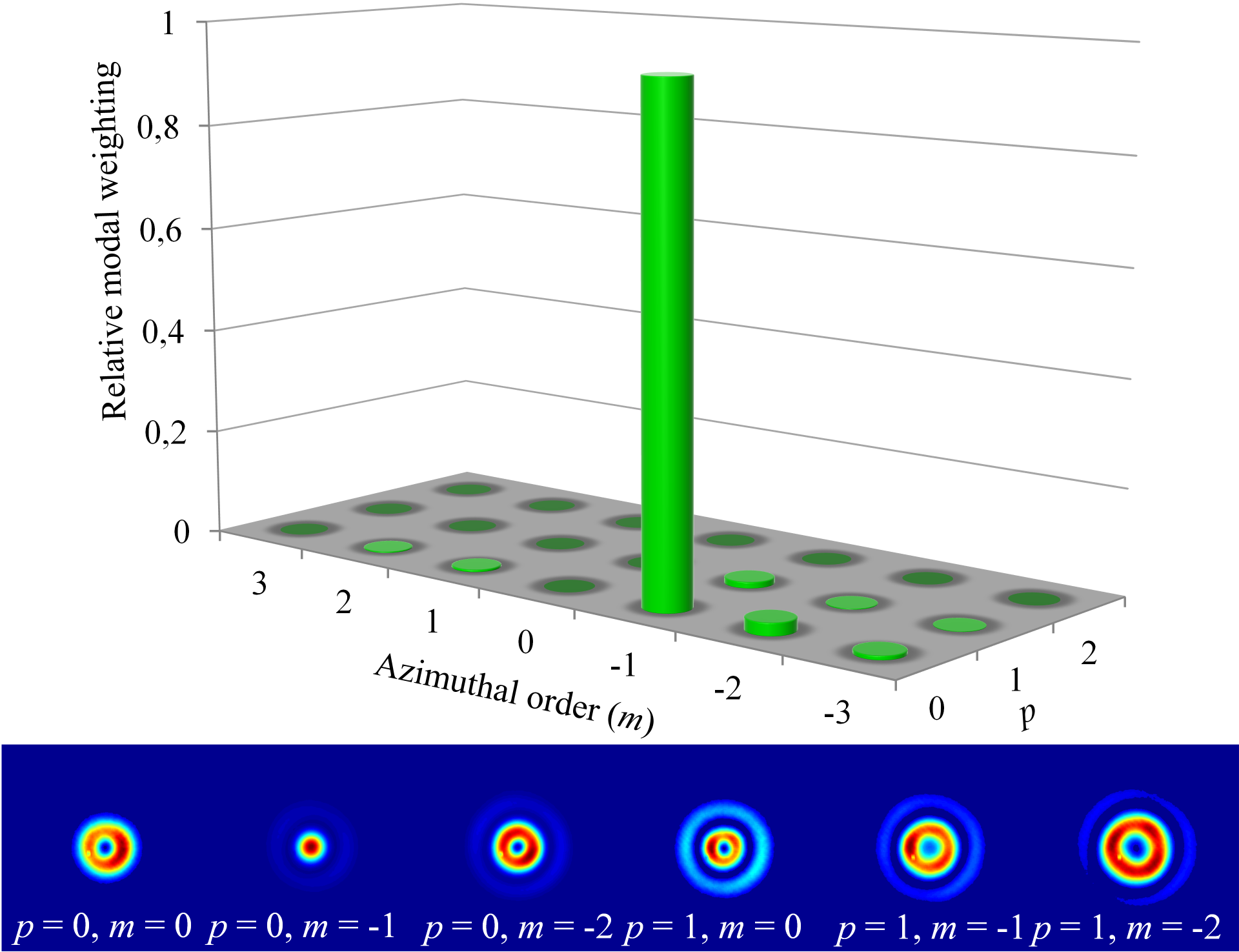
Experimentally the unknown field is directed onto a spatial light modulator (SLM) that is electronically addressed with an appropriate transmission function . The resultant field is Fourier transformed with a thin optical lens by positioning the lens a focal length from the plane of the SLM and the intensity measurement to determine the relative weightings (Eq. (23)) is performed at a focal length beyond the lens. The transmission function as addressed to the SLM is coupled with a linear grating employed as a phase carrier to separate the first order of diffraction from the zeroth and unwanted diffraction orders and the intensity at the centre of the first diffraction order is sampled to determine the relative weightings. This experimental procedure was executed on the output of the optical cavity operated at , and . The basis set for the decomposition was chosen to be the Laguerre-Gaussian set and the transmission functions were varied from through with through to and as illustrated in Fig. 10, we obtain an on-axis intensity signal for a Laguerre-Gaussian mode of radial order, and azimuthal order with zero for all other modes which affirms a pure LG0-1 mode at the output. The Gaussian width in the Laguerre-Gaussian function was chosen from the cavity design parameters.
References
- (1) B. Piccirillo, S. Slussarenko, L. Marrucci, E. Santamato, Rivista Del Nuovo Cimento 36, 501 (2013).
- (2) B. Piccirillo, V. D Ambrosio, S. Slussarenko, L. Marrucci, E. Santamato, Appl. Phys. Lett. 97, 241104 (2010).
- (3) S. Slussarenko, et al., Opt. Exp. 19, 4085 (2011).
- (4) E. Karimi, B. Piccirillo, L. Marrucci, E. Santamato, Opt. Lett. 34, 1225 (2009).
- (5) L. Marucci, C. Manzo, D. Paparo, Phys. Rev. Lett. 96, 163905 (2006).
- (6) L. Marucci, C. Manzo, D. Paparo, Appl. Phys. Lett. 88, 221102 (2006).
- (7) L. Marrucci, Mol. Cryst. Liq. Cryst. 488, 148 (2008).
- (8) For the special case , one also needs to specify an additional angle such that . For the other cases the angle can be absorbed in the definition of the q-plate rotation angle , as defined in Eq. (14).