Cooling and Manipulation of a levitated nanoparticle with an optical fiber trap
Abstract
Accurate delivery of small targets in high vacuum is a pivotal task in many branches of science and technology. Beyond the different strategies developed for atoms, proteins, macroscopic clusters and pellets, the manipulation of neutral particles over macroscopic distances still poses a formidable challenge. Here we report an approach based on a mobile optical trap operated under feedback control that enables cooling and long range 3D manipulation of a silica nanoparticle in high vacuum. We apply this technique to load a single nanoparticle into a high-finesse optical cavity through a load-lock vacuum system. We foresee our scheme to benefit the field of optomechanics with levitating nano-objects as well as ultrasensitive detection and monitoring.
pacs:
42.50.Wk, 07.10.Pz, 62.25.FgControlled manipulation of matter over long distances in high vacuum has enabled many groundbreaking experiments, including protein characterization via x-ray diffraction Chapman et al. (2011), macroscopic quantum interference Hornberger et al. (2012); Romero-Isart et al. (2011), laser induced fusion Nakai and Mima (2004), and quantum information processing Kuhr et al. (2001). The sample size ranges from sub-nanometer for single atoms Kuhr et al. (2001) up to a few millimeters for laser fusion pellets. To avoid unwanted interactions, microscopic samples can be confined in levitation using Paul traps Paul (1990) or optical fields Ritsch et al. (2013). These potentials usually extend over small regions on the order of few microns. Therefore, a delivery method is needed in order to position the sample of interest into the region of stable potential.
Atoms and small molecules on a substrate can be delivered into the gas phase through heating, since the additional thermal energy is sufficient to overcome the potential barrier caused by the attractive Van der Waals interaction between the sample and the substrate. In contrast, larger objects remain stuck because the Van der Waals interaction increases with size. For micron sized objects, the interaction can be overcome mechanically by shaking the substrate with a piezoelectric transducer Ashkin (1971); Li et al. (2011), allowing the particle to build up enough kinetic energy to escape the interaction potential. However, as this approach relies on the object’s mass, it cannot be applied to particles smaller than .
The advent of electrospray ionization partially closed this gap by delivering macromolecules and nanoparticles in solution into the gas phase Fenn et al. (1989). Electrospray ionization generates fast highly charged particles, which are then guided with electrical forces into the vacuum chamber Paul (1990); Kuhlicke et al. (2015). However, charged particles are not always desirable and neutral particles cannot be manipulated by electrical forces.
An approach in the context of recent optomechanical experiments with an optically trapped nanoparticle, uses a nebulizer to deliver neutral particles from solution into the gas phase Ashkin (1971); Gieseler et al. (2012); Summers et al. (2008). Neutral particles are trapped under ambient conditions and the pressure is reduced while the particle is trapped. Despite its simplicity, this approach is not ideal since it compromises the ultimate vacuum and excess particles degrade the performance of ultra-high reflectivity mirrors, which are required for cavity optomechanics Romero-Isart et al. (2010); Chang et al. (2010); Kiesel et al. (2013).
To maintain ultra clean conditions it becomes necessary to physically separate the particle injection region from the experiment and introduce a transport mechanism between them. Conventional optical manipulation techniques based on tracking interference patterns or non-diffracting beams Čižmár et al. (2005) are limited to travel ranges below , which is insufficient to cover the distance between adjacent vacuum chambers. Hollow core optical fibers Schmidt et al. (2012a, b) can overcome this limitation. Yet, their use for fine delivery in high vacuum is still to be demonstrated Grass (2013). Additionally, if no other feedback stabilization mechanisms are used, optically trapped particles in vacuum conditions escape the trap below 1mBar due to a poorly understood mechanism that has been reported by several groupsMillen et al. (2014); Kiesel et al. (2013); Price et al. (2015), thus limiting the pressure range in which experiments can be performed.
In this letter we address these difficulties by using a load-lock scheme with a mobile trap. Particles are loaded under ambient pressure in a first vacuum chamber and then transferred under vacuum into a high finesse cavity inside a second vacuum chamber. Additionally, our trap integrates a detection scheme that follows the particle’s motion over arbitrarily long manipulation distances, providing the information required to implement a particle stabilization mechanism. This adds to our high vacuum trapping capabilities the ability to manipulate levitated nano-objects over large distances.
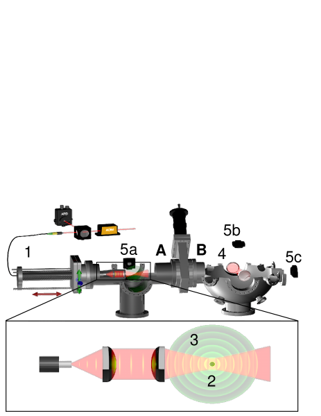
Figure 1 shows the experimental setup. The mobile optical trap (MobOT) consists of an optical fiber, a collimator and a high numerical aperture aspheric lens (NA=0.8), which are mounted together on a metal rod inside our vacuum system. The metal rod is attached to a translation stage equipped with three stepper motors. The stepper motors allow us to move the MobOT in all three spatial directions with 2/step. The step size is given by the ratio of the gears used to actuate the translation stage and can be reduced on detriment of speed.
Infrared light () from a free space laser is coupled into the fiber and sent through the fiber into the vacuum chamber, where it is out-coupled with the collimator and focused by the aspheric lens to form a stable optical trap mm away from the surface of the lens.
As in previous experiments Gieseler et al. (2012, 2014a) we use a nebulizer to load the optical trap with a single nanoparticle with radius .
The particle scatters light from the trapping beam. The backscattered light is collected with the same aspheric lens used for focusing, coupled back into the fiber via the collimator and sent to an avalanche photodiode (APD). At the APD, the backscattered light from the nanoparticle interferes with laser light that is reflected at the end facet of the vacuum side fiber, acting as a reference arm in a homodyne detection scheme. The intensity at the APD is, thus, given by
| (1) |
where () and () are the electric field amplitude (phase) of the backscattered light from the particle and reference, respectively.
The radiation pattern of a subwavelength dielectric particle is well approximated by a dipole and, to lowest order, the position of the particle along the optical axis is imprinted only onto the phase of the backscattered light . Here, is an arbitrary relative phase between a stationary particle in the trap center and the reference beam, and is the phase change of the particle due to its motion along the optical axis, where is the wavevector. Note that a small displacement of along the optical axis, leads to 2 optical path difference between the backscattered and the reference light. For a periodic motion the last term of equation (1) reads
| (2) |
where we used the Jacobi-Anger expansion Abramowitz and Stegun (1964).
Thus, the right term of equation (2) is a sum of harmonics of the particle oscillation frequency where the relative strength of each harmonic is given by a Bessel function .”
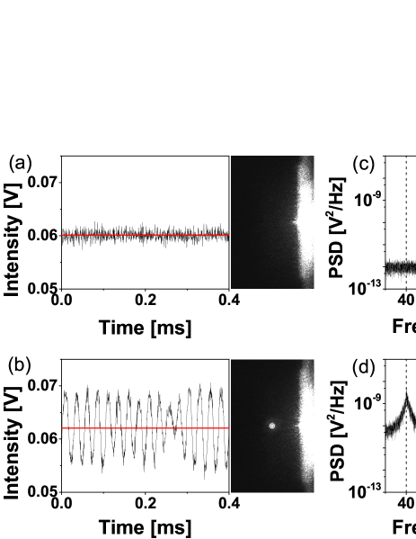
Figure 2 shows a characteristic time trace and power spectral density (PSD) of the detector signal measured with a nanoparticle trapped at . We clearly resolve the oscillatory underdamped motion Li et al. (2010) and observe up to four harmonics of the fundamental frequency at . From the ratio of the and harmonic we retrieve in excelent agreement with what is expected (191nm) from the equipartition theorem , where and is Boltzmann’s constant, , and . In addition to the particle oscillations, the APD signal in presence of the particle (Fig. 2b)differs from the APD signal without a particle (Fig. 2a)) by an offset. This offset originates from the terms and in equation (1) and equation (2), respectively. Remarkably, our detection scheme enables us to follow the particle motion over arbitrary distances. This is in stark contrast to common stationary detection methods, where the detection range is of the order of the particle diameter for quadrant photo detectors (QPDs) based methods Martínez and Petrov (2012) or limited by the field of view for camera based detection Millen et al. (2015, 2014).
The detection signal is used to feedback stabilize the particle in the MobOT at pressures below 1mBar. In contrast to previous schemes Li et al. (2011); Ashkin and Dziedzic (1977); Gieseler et al. (2012), our feedback does not depend on a precise phase relationship between the particle motion and the parametric feedback force. Instead, it measures abrupt changes in the detector signal and penalizes large amplitude oscillations by increasing the trap stiffness akin to a plasmonic self-induced back action trap Juan et al. (2009)
The oscillation amplitude of the trapped particle changes randomly due to stochastic collisions between the particle and residual air molecules. The timescale over which the amplitude changes is determined by the damping coefficient Gieseler et al. (2014b). The damping coefficient depends linearly on the gas pressure Gieseler et al. (2012) and is much smaller than the oscillation frequency under vacuum conditions (underdamped regime) Beresnev et al. (1990). The relatively slow change in amplitude allows us to implement the feedback in a FPGA. We sample the detector signal at . For each sample we measure its deviation from the current mean and compare it to the standard deviation over the last samples, which corresponds to one oscillation period. To cool the particle, we modulate the laser intensity with an acousto-optic modulator (AOM) according to
| (3) |
where is the laser intensity without feedback and is the laser modulation depth.
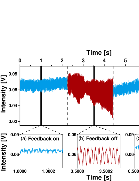
Since the trap stiffness , this scheme penalizes large oscillation amplitudes by stiffening the trap whenever the amplitude becomes too large, leading to an overall reduction in the particle oscillation amplitude as shown in Fig. 3.
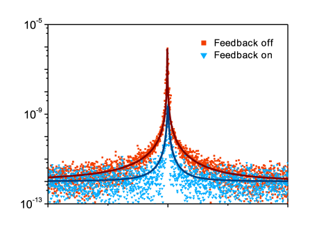
According to the equipartition theorem, a static increase of the laser power decreases the oscillation amplitude , while increasing the oscillation frequency . Fig. 4 shows the PSD of the detector signal with and without feedback. The oscillation frequency shifts only slightly to higher frequencies under feedback. This demonstrates that our feedback increases the average laser power only very little. The feedback damping also manifests itself as an 8 fold increase in the resonance linewidth. According to Gieseler et al.Gieseler et al. (2012), we can estimate the center of mass temperature () from the additional optical damping as:
| (4) |
Where is the temperature of the phonon thermal bath, its dissipation and the additional dissipation rate introduced by the optical feedback. This corresponds to 40K. It is worth noticing that due to the nonlinearity of the Bessel functions in equation (2) and especially the nonlinear broadening at low pressures without feedback Gieseler et al. (2013), we might overestimate with respect to , leading to an underestimate of the cooling efficiency. This trend is corroborated by comparing the variance of the signal traces, which gives .
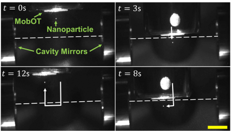
We use the MobOT to stabilize a nanoparticle and to translate it between two vacuum chambers, which are separated by a valve and apart (A and B Fig.1). First, we trap a particle in chamber A under ambient pressure, while we keep chamber B at . We then reduce the pressure in chamber A to and activate the feedback. When chamber A has reached we slowly open the valve. This equilibrates the pressure between the two chambers at . Once the equilibrium pressure has been reached, we push the metal rod into chamber B at an average speed of , which takes about 6 min vid . At the center of the second vacuum chamber, which hosts a high finesse optical cavity (F estimated by ringdown measurements), we observe the MobOT through the top window using an external camera (camera 5b in Fig. 1). Fig. (5)(Multimedia view) shows a sequence of camera images as we translate the trapped particle in the plane, demonstrating our excellent control of the particle position throughout the cavity.
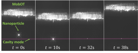
Finally, we use the MobOT to transfer the particle into the cavity field as shown in Fig .6(Multimedia view). From time =0s to we position the particle to the cavity mode (65m waist) by fine tuning the position of the trap into the three axis. Then, at we increase the intracavity power to 70W, allowing the particle to jump from one trap to the other. At this point we retract the MobOT to check that the particle is kept traped by the cavity field. Few seconds after the transfer, the particle escapes the cavity field as reported by other groups Kiesel et al. (2013).
In conclusion, we have demonstrated position detection of a levitated particle collecting the backscattered light through a fibre. In combination with a mobile optical trap under feedback and a load-lock scheme, it enabled us to translate a levitated particle over long distances and to accurately position it in three dimensions allowing transfer between different trapping potentials even under high vacuum conditions. Our method could be used to deliver nano-objects of different sizes as long as they experience trap depths larger than 10, Ashkin et al. (1986). Using the dipole approximation, we estimated a trap depth for the MobOT of . Hence, using the same power we should be able to deliver particles with sizes down to 50nm radius (limited by the particle polarizability). An unpper size bound appears when the particle is larger than the MobOT spot size, therfore we should not be able to trap and deliver particles larger than m diameter.
We envision that our approach will enable many exciting experiments that require to deliver a nanometer sized object into a clean high vacuum, such as cavity optomechanics with one or multiple particles to study macroscopic quantum mechanics Romero-Isart et al. (2011), phase transitions Lechner et al. (2013), short range forces Geraci et al. (2010), nanoscale heat transport Chiloyan et al. (2015), coherent particle-particle interactions Okamoto et al. (2013) and gravitational waves Arvanitaki and Geraci (2013).
Acknowledgments
PM, JB and RQ acknowledge financial support from the Fundació Privada Cellex Barcelona, CoG ERC QnanoMECA (No. 64790), the Spanish Ministry of Economy and Competitiveness (grant FPU-AP-2012-3729 and FIS2013-46141-P). MS acknowledges financial support from the Ministry of Science and Technology of the Republic of Serbia (project OI171005) and Marie Curie COFUND (FP7-PEOPLE-2010-COFUND). LN and JG acknowledge financial support from ERC-QMES (no. 338763).
References
- Chapman et al. (2011) H. N. Chapman, P. Fromme, A. Barty, T. A. White, R. A. Kirian, A. Aquila, M. S. Hunter, J. Schulz, D. P. DePonte, U. Weierstall, R. B. Doak, F. R. N. C. Maia, A. V. Martin, I. Schlichting, L. Lomb, N. Coppola, R. L. Shoeman, S. W. Epp, R. Hartmann, D. Rolles, A. Rudenko, L. Foucar, N. Kimmel, G. Weidenspointner, P. Holl, M. Liang, M. Barthelmess, C. Caleman, S. Boutet, M. J. Bogan, J. Krzywinski, C. Bostedt, S. Bajt, L. Gumprecht, B. Rudek, B. Erk, C. Schmidt, A. Hömke, C. Reich, D. Pietschner, L. Strüder, G. Hauser, H. Gorke, J. Ullrich, S. Herrmann, G. Schaller, F. Schopper, H. Soltau, K.-U. Kühnel, M. Messerschmidt, J. D. Bozek, S. P. Hau-Riege, M. Frank, C. Y. Hampton, R. G. Sierra, D. Starodub, G. J. Williams, J. Hajdu, N. Timneanu, M. M. Seibert, J. Andreasson, A. Rocker, O. Jönsson, M. Svenda, S. Stern, K. Nass, R. Andritschke, C.-D. Schröter, F. Krasniqi, M. Bott, K. E. Schmidt, X. Wang, I. Grotjohann, J. M. Holton, T. R. M. Barends, R. Neutze, S. Marchesini, R. Fromme, S. Schorb, D. Rupp, M. Adolph, T. Gorkhover, I. Andersson, H. Hirsemann, G. Potdevin, H. Graafsma, B. Nilsson, and J. C. H. Spence, Nature 469, 73 (2011).
- Hornberger et al. (2012) K. Hornberger, S. Gerlich, P. Haslinger, S. Nimmrichter, and M. Arndt, Reviews of Modern Physics 84, 157 (2012).
- Romero-Isart et al. (2011) O. Romero-Isart, A. Pflanzer, F. Blaser, R. Kaltenbaek, N. Kiesel, M. Aspelmeyer, and J. Cirac, Physical Review Letters 107, 020405 (2011).
- Nakai and Mima (2004) S. Nakai and K. Mima, Rep. Prog. Phys. 67, 321 (2004).
- Kuhr et al. (2001) S. Kuhr, W. Alt, D. Schrader, M. Müller, V. Gomer, and D. Meschede, Science 293, 278 (2001).
- Paul (1990) W. Paul, Reviews of modern physics 62, 531 (1990).
- Ritsch et al. (2013) H. Ritsch, P. Domokos, F. Brennecke, and T. Esslinger, Reviews of Modern Physics 85, 553 (2013).
- Ashkin (1971) A. Ashkin, Appl. Phys. Lett. 19, 283 (1971).
- Li et al. (2011) T. Li, S. Kheifets, and M. G. Raizen, Nature Physics 7, 527 (2011).
- Fenn et al. (1989) J. Fenn, M. Mann, C. Meng, S. Wong, and C. Whitehouse, Science 246, 64 (1989).
- Kuhlicke et al. (2015) A. Kuhlicke, A. Rylke, and O. Benson, Nano letters 15, 1993 (2015).
- Gieseler et al. (2012) J. Gieseler, B. Deutsch, R. Quidant, and L. Novotny, Physical Review Letters 109, 103603 (2012).
- Summers et al. (2008) M. D. Summers, D. R. Burnham, and D. McGloin, Optics express 16, 7739 (2008).
- Romero-Isart et al. (2010) O. Romero-Isart, M. L. Juan, R. Quidant, and J. I. Cirac, New J. Phys. 12, 033015 (2010).
- Chang et al. (2010) D. E. Chang, C. Regal, S. Papp, D. Wilson, J. Ye, O. Painter, H. J. Kimble, and P. Zoller, Proceedings of the National Academy of Sciences 107, 1005 (2010).
- Kiesel et al. (2013) N. Kiesel, F. Blaser, U. Delić, D. Grass, R. Kaltenbaek, and M. Aspelmeyer, Proceedings of the National Academy of Sciences 110, 14180 (2013).
- Čižmár et al. (2005) T. Čižmár, V. Garcés-Chávez, K. Dholakia, and P. Zemánek, Appl. Phys. Lett. 86, 174101 (2005).
- Schmidt et al. (2012a) O. A. Schmidt, M. K. Garbos, T. G. Euser, and P. S. J. Russell, Physical Review Letters 109, 024502 (2012a).
- Schmidt et al. (2012b) O. A. Schmidt, M. K. Garbos, T. G. Euser, and P. S. J. Russell, Opt. Lett. 37, 91 (2012b).
- Grass (2013) D. Grass, Optical trapping and transport of nanoparticles with hollow core photonic crystal fibers (University of Vienna, 2013).
- Millen et al. (2014) J. Millen, T. Deesuwan, P. Barker, and J. Anders, Nature Nanotechnology 9, 425 (2014).
- Price et al. (2015) C. Price, T. Donnelly, S. Giltrap, N. Stuart, S. Parker, S. Patankar, H. Lowe, D. Drew, E. Gumbrell, and R. Smith, Review of Scientific Instruments 86, 033502 (2015).
- Gieseler et al. (2014a) J. Gieseler, M. Spasenović, L. Novotny, and R. Quidant, Physical Review Letters 112, 103603 (2014a).
- Abramowitz and Stegun (1964) M. Abramowitz and I. A. Stegun, Handbook of mathematical functions: with formulas, graphs, and mathematical tables, 55 (Courier Corporation, 1964).
- Li et al. (2010) T. Li, S. Kheifets, D. Medellin, and M. Raizen, Science 328, 1673 (2010).
- Martínez and Petrov (2012) I. A. Martínez and D. Petrov, Applied Optics 51, 5973 (2012).
- Millen et al. (2015) J. Millen, P. Fonseca, T. Mavrogordatos, T. Monteiro, and P. Barker, Physical Review Letters 114, 123602 (2015).
- Ashkin and Dziedzic (1977) A. Ashkin and J. M. Dziedzic, Appl. Phys. Lett. 30, 202 (1977).
- Juan et al. (2009) M. L. Juan, R. Gordon, Y. Pang, F. Eftekhari, and R. Quidant, Nature Physics 5, 915 (2009).
- Gieseler et al. (2014b) J. Gieseler, R. Quidant, C. Dellago, and L. Novotny, Nature Nanotechnology 9, 358 (2014b).
- Beresnev et al. (1990) S. A. Beresnev, V. G. Chernyak, and G. A. Fomyagin, Journal of Fluid Mechanics 219, 405 (1990).
- Gieseler et al. (2013) J. Gieseler, L. Novotny, and R. Quidant, Nature Physics 9, 806 (2013).
- (33) See supplemental material at [ URL will be inserted by AIP] for record of the full loading process.
- Ashkin et al. (1986) A. Ashkin, J. Dziedzic, J. Bjorkholm, and S. Chu, Optics letters 11, 288 (1986).
- Lechner et al. (2013) W. Lechner, S. J. M. Habraken, N. Kiesel, M. Aspelmeyer, and P. Zoller, Physical Review Letters 110, 143604 (2013).
- Geraci et al. (2010) A. A. Geraci, S. B. Papp, and J. Kitching, Physical Review Letters 105, 101101 (2010).
- Chiloyan et al. (2015) V. Chiloyan, J. Garg, K. Esfarjani, and G. Chen, Nature Communications 6 (2015).
- Okamoto et al. (2013) H. Okamoto, A. Gourgout, C.-Y. Chang, K. Onomitsu, I. Mahboob, E. Y. Chang, and H. Yamaguchi, Nature Physics 9, 480 (2013).
- Arvanitaki and Geraci (2013) A. Arvanitaki and A. A. Geraci, Physical Review Letters 110, 071105 (2013).