Wide-Range Tunable Dynamic Property of Carbon Nanotube-Based Fibers
Abstract
Carbon nanotube (CNT) fiber is formed by assembling millions of individual tubes. The assembly feature provides the fiber with rich interface structures and thus various ways of energy dissipation, as reflected by the non-zero loss tangent (0.028–0.045) at low vibration frequencies. A fiber containing entangled CNTs possesses higher loss tangents than a fiber spun from aligned CNTs. Liquid densification and polymer infiltration, the two common ways to increase the interfacial friction and thus the fiber’s tensile strength and modulus, are found to efficiently reduce the damping coefficient. This is because the sliding tendency between CNT bundles can also be well suppressed by the high packing density and the formation of covalent polymer cross-links within the fiber. The CNT/bismaleimide composite fiber exhibited the smallest loss tangent, nearly as the same as that of carbon fibers. At a higher level of the assembly structure, namely a multi-ply CNT yarn, the inter-fiber friction and sliding tendency obviously influence the yarn’s damping performance, and the loss tangent can be tuned within a wide range, as similar to carbon fibers, nylon yarns, or cotton yarns. The wide-range tunable dynamic properties allow new applications ranging from high quality factor materials to dissipative systems.
Natural and synthetic fibers are used in many products and play a large role in everyday applications. Their mechanical properties are important both from the point of view of fiber processing in a technological process and their use in the form of final products. Besides the quasi-static properties including the fiber’s tensile strength (), elastic modulus (), and fracture toughness (), the dynamic response to a periodic external signal (displacement or force) can be severe due to the energy dissipation menard.kp:1999 . Obviously, frictional effects play a major role in the dynamic response. However, the types of friction differ greatly between a thread, yarn, and fiber due to their different assembly structures.
Fiber is usually defined as a hair-like strand of material and is the smallest “visible” unit of a fabric. Natural fibers (cotton, flax, jute, bamboo, kapok, ramie, wool, silk, and spider silk) and synthetic fibers (nylon, glass fiber, cellulose fiber, and carbon fiber) usually have a width (diameter) ranging from several to tens of m, and a length at least 100 times longer than the width. Yarn is a continuous length of interlocked fibers used for manufacturing textiles hearle.jws:20011 . At the uppermost structure level, threads are usually made by plying and twisting yarns, for efficient and smooth stitching in sewn products.
When carbon nanotubes (CNTs) are assembled into a strand by a spinning process jiang.kl:2002 ; zhang.m:2004 ; li.yl:2004 ; motta.m:2007 ; jia.jj:2011 ; zhang.xh:2012 ; lu.wb:2012 , a new man-made or synthetic fiber is formed. A CNT fiber with a diameter of 10 usually contains more than individual CNTs. Such assembly feature is different from those fibers well-known for many years which are usually a solid structure without internal interfaces. CNT fiber can also be considered as a continuous length of interlocked “filaments” (CNT bundles) zhao.jn:2010 , where the bundles are formed during the CNT growth rather than in the spinning process. Although also being called as CNT yarn, CNT fiber is indeed not a yarn because the CNT bundles are not macroscopically processable. On the contrary, the basic components of a yarn, the long and parallel or interlocked filaments, are usually processable objects with a width larger than several hearle.jws:20011 .
As similar to the relationship between fiber and yarn, the friction between CNT bundles should also be the most important way to dissipate energy in the dynamic responses of CNT fiber. In this paper a method for investigating inter-bundle friction in CNT fiber is presented and the effect of interfacial enhancement on friction is shown. For the pure CNT fibers, the higher level of densification, the lower loss tangent. The introduction of covalent polymer networking can also reduce remarkably the damping phenomenon. For these two situations, although the increase in frictional force results in higher “localized” energy dissipations, the “overall” sliding tendency between CNT bundles can be remarkably suppressed due to the increased interfacial interactions and the covalent networks. However, by tuning the type of CNT/polymer network from covalent to non-covalent and using different polymer chain lengths, the loss tangent can be tailored within a wide range. Furthermore, the spinning CNT fibers into a multi-ply CNT yarn is another important way to make them behavior like carbon fibers, nylon yarns, or cotton yarns. With considering that the CNT fibers are flexible, electrically conductive, and mechanically strong, the tunable dynamic property can well extend their applications ranging from high quality factor materials to dissipative systems.
A modified Kelvin-Voigt model was adopted according to the studies on staple yarns murayama.t:1979 , where three elements are connected in parallel to study the dynamic responses of CNT fibers (Figure 1). These elements include a linear elastic spring which stores energy (i.e., the fiber’s modulus ), an energy dissipation mechanism associated with the internal viscosity of the filaments or CNT bundles, and an energy dissipation mechanism of the coulomb form associated with the sum of inter-bundle friction . One should notice that due to the hierarchical feature is also related to the inter-tube friction within a CNT bundle.

When a sinusoidal displacement is applied, and being the amplitude and frequency, the energy dissipations per cycle due to and are
| (1) | |||
| (2) |
By using an effective coefficient , the total energy dissipated can be represented by .
The force output is
| (3) |
where
| (4) |
This means that the effective damping loss tangent () contains frequency- and friction-dependent components. The traditional dynamic tests can just directly measure the effective loss tangent rather than the inter-bundle friction or the bundle’s internal viscosity for CNT fibers. However, by applying tests upon different and , it might be possible to study them separately, and in the present study the major interests have been focused on the inter-bundle frictional properties.
The dynamic properties were measured with a Keysight T150 Universal Testing Machine under the Continuous Dynamic Analysis (CDA) option, a direct and accurate way to measure the specimen’s stiffness upon an additional vibrational load input. As the displacement and force can be collected at each point in the experiment, it becomes possible to analyze their amplitude vibrations and phase relationships, thus making it possible to determine the storage modulus () and loss modulus () keysight . Notice that, due to the way to introduce vibrations in the T150 system, the amplitude of vibration is controlled by the change in load force () rather than the displacement variation. The default value mN was used, which is less than 5% of the fracture force for CNT fibers. Such value usually resulted in a displacement amplitude of –3.5 for all the samples in the present study (see the analysis in Experimental Section).
Figure 2a and b show two dynamic tests performed on ethylene glycol (EG)-densified CNT fibers at 30 and 100 Hz. Upon increasing the tensile strain (), instantaneous engineering stress (), , and were obtained. The ratio between the loss and storage moduli, , quickly increased up after the beginning of stretching and was maintained until the fiber fracture. This provided an efficient way to measure the dynamic property, i.e., by averaging the instantaneous values during the tensile test.
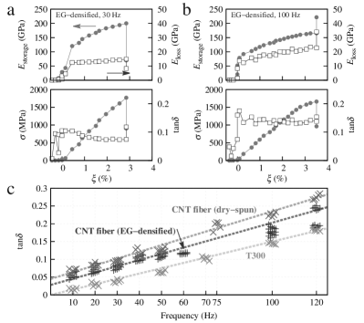
There existed a linear dependence of on the frequency (), see Figure 2c, in agreement with the analytical result (Equation 4). However, by comparing to the dry-spun CNT fibers (see Experimental Section) and Toray T300 carbon fibers, two remarkable differences can be observed. For the one hand, the -to- slope for both types of CNT fibers was larger than that of the T300. On the other hand, by extrapolating to zero, at was non zero for the CNT fibers while it was nearly zero for the T300. These two quantitative differences provided us a new way to study the frictional properties for CNT fibers.
The different -to- slopes mainly captured the difference in elastic modulus according to Equation 4. was measured to be 204–238 GPa for the T300 carbon fiber (in agreement with their data sheet t300 ), while it was 45–59 GPa and 72–101 GPa for the dry-spun and EG-densified CNT fibers, respectively (see also our previous results zhao.jn:2010 ; jia.jj:2011 ; li.s:2012 ). As there should not be significant difference in the intrinsic viscosity for the sp2 structures in CNT and carbon fiber, the difference in obviously became the major source for the different linear - relationship. Furthermore, such difference also influences greatly the quality factor, which might range from several hundred (for GPa, like glass-reinforced plastic wei.cy:2000 ) to over 5000 (for –470 GPa, like carbon fiber castellanos-gomez.a:2010 and sapphire fiber uchiyama.t:2000 ). Thus to develop CNT fibers as high quality factor materials, further improvement in modulus is of great necessity.
The non-zero extrapolated at means that even without external vibrations, there always existed energy losses at CNT interfaces. For the dry-spun and EG-densified CNT fibers and 0.028, respectively. Such difference well reflected their different frictional feature in different assembly levels of CNTs. Notice that, in a recent study, the passive damping of dry-spun CNT fibers exhibited energy loss ratio of 0.05 during a hysteresis test at 0.1 Hz hehr.a:2014 , in good agreement with our extrapolated results.
To show the assembly dependence in more detail, various CNT-based assembly fibers were used. Besides the dry-spun and EG-densified CNT fibers which were produced based on the array spinning method jiang.kl:2002 ; zhang.m:2004 ; zhang.xb:2006 ; li.qw:2006 , some CNT fibers were obtained by directly spinning the aerogel-like CNT networks which were grown with an injection chemical vapor deposition (iCVD) li.yl:2004 ; motta.m:2007 ; stano.kl:2008 and thus were named iCVD fibers.
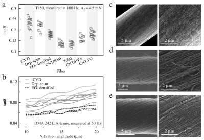
Figure 3a shows the comparison on for these different CNT fibers. The first attention was paid to the three “pure” CNT fibers, namely the iCVD, dry-spun, and EG-densified fibers, where the CNT weight percent was over at least 95% li.s:2012 ; zhong.xh:2010 . The iCVD and dry-spun CNT fiber had the highest loss tangents, averages of 0.229 and 0.218 at 100 Hz, respectively. When EG densification was introduced during the fiber spinning li.s:2012 , the averaged at 100 Hz decreased to 0.178. This difference can also be detected with a DMA 242 E Artemis (Dynamic Mechanical Analyzer, see Experimental Section). By increasing the vibration amplitude from 10 to 20 at 50 Hz, the instantaneous always exhibited the same sequence: iCVD dry-spun EG-densified (Figure 3b).
It is necessary to point out that the vibration frequency in everyday life is usually not such high. Here we measured at 50 and 100 Hz just in order to show better comparisons as the data variation was small as compared with its magnitude.
To analyze the assembly dependence, scanning electron microscopy (SEM) were performed for these CNT fibers, as shown in Figure 3c-e. For the iCVD CNT assemblies, the entangled CNT network (Figure 3c) contributed other ways of energy dissipation rather than the inter-bundle (inter-filament) friction. As reported in our previous study liu.ql:2014 , the CNT network deformation was the main way to carry and transfer external loads and the stress-strain curve clearly showed a wide plastic range, about from 2.5% to 30% in tensile strain. The inelastic structural change at the CNT cross-links costed energies upon small vibrations and the slippage between CNTs provided another energy-cost process at large strains. These structural changes at the cross-links were also named detaching-attaching and zipping-unzipping processes li.y:2012 . On the contrary, the CNTs in the dry-spun fibers were aligned and the number of CNT cross-links was much fewer than that in the iCVD network (Figure 3d). However, their packing density was not high and the CNT bundles can easily slide with each other. Such assembly feature resulted in frictional energy consumption and thus the high loss tangent koratkar.n:2002 ; koratkar.na:2003 ; suhr.j:2005 . After the EG densification, the improved packing density increased the inter-bundle contact area and enhanced the interfacial frictional force. Such change would increase the frictional energy dissipation according to Equation 2. However, the tendency of CNT slippage was remarkably suppressed due to the high packing density, corresponding to the reduced number for summing up Equation 2. Therefore, the overall energy dissipation was also suppressed.
Thus it is necessary to re-consider the content of Equation 4. Accurately, describes the level of overall frictional energy dissipation, reflecting not only the magnitude of frictional force but also the total number of interfaces where sliding phenomenon might take place. Therefore, to develop CNT fibers as high quality factor or low damping materials, the inter-bundle structure design becomes the key route.
The tailoring on interface structure and interaction had effects not only on the damping property but also on the quasi-static mechanical performances. For example, the liquid-induced high CNT packing density reduced the frictional energy dissipation and also increased the tensile strength and modulus. The EG-densified CNT fibers demonstrated a strength of 1.65–1.82 GPa and a modulus of 72–101 GPa (Figure 2a and b), of 500 MPa and 40 GPa higher than those of the dry-spun fibers jia.jj:2011 ; li.s:2012 . This means that the strengthening methods might also have significant effects on the tailoring of the dynamic property. For this purpose, polymer molecules such as polyvinyl alcohol (PVA), polyurethane (PU), and bismaleimide (BMI) were infiltrated into CNT fibers as they all improved the tensile properties significantly fang.c:2010 ; li.s:2012 .
The CNT/BMI composite fiber demonstrated the smallest loss tangent, which varied from 0.122 to 0.157 with an average of 0.136 at 100 Hz. Such value was very close to that for T300 (variation of 0.115–0.149 and average of 0.134), see Figure 3a. The infiltrated thermosetting BMI resins formed cross-lined polymer network within CNT fibers by a curing process li.s:2012 , and such networking effect further suppressed the sliding tendency. By considering the high tensile strength (up to 2.47 GPa) and high modulus (up to 110–140 GPa) li.s:2012 ; meng.fc:2014 , the CNT/BMI composite fiber can be used as excellent high quality factor materials.
On the contrary, when thermoplastic polymers were introduced, although the inter-bundle interaction can be improved, the viscosity of PVA or PU introduced new mechanisms to viscoelastically dissipate the energy yang.sy:2007 . Besides this, the non-covalent interactions between the polymer molecule and CNT also resulted in network deformation upon external strains. As a result, the measured was higher than that of the CNT/BMI composite fiber ( for the CNT/PVA and 0.18 for the CNT/PU, Figure 3a). Notice that although the interaction between CNT and BMI was non-covalent, the covalently bonded BMI network obviously was much more rigid than the non-covalently entangled PVA and PU networks. The polymer chain length of BMI was also much shorter than that of PVA and PU. These differences obviously resulted in different movability of CNT and thus the totally different dynamic properties.
Therefore, for the highly packed CNT assemblies, the introduction of thermoplastic or thermosetting polymers can be an efficient way to increase or decrease the loss tangent (while the tensile strength and modulus were both improved upon the polymer infiltration li.s:2012 ), and can be used for developing assembly fibers with a designed quality factor.
In textile industry, the spun agglomeration of fibers, named a yarn, is used for knitting, weaving, or sewing. The simplest way to produce a CNT yarn is the multi-ply spinning. Figure 4a shows the SEM images of a 7-ply and 40-ply CNT yarn. Obviously, the multi-plying introduced the inter-fiber contacts as new sources of frictional energy dissipation. By using the DMA 242 E Artemis with and Hz, the dynamic properties of these different yarns were characterized, as shown in Figure 4b (the low frequency may often take place in reality and the results can be compared to Figure 2c). A logarithmic dependence of was observed with increasing the number of plies (), see Figure 4b. monotonically increased with because the inter-fiber contact areas increased to contribute more energy dissipations. However, the dependence was not linear as the spinning treatment also hindered the sliding tendency between CNT fibers. The simply multi-plying resulted in the highest loss tangent as shown in Figure 4b, e.g., for the 400-ply yarn which had a linear density about 65 tex, that is, 65 g per kilometer. When adhesion between the CNT fibers was also introduced in the multi-plying with polymer molecules, just like the enhanced inter-bundle interaction with infiltrated polymers within a CNT fiber, the loss tangent also decreased slightly. For example, the PVA-adhered 400-ply yarn exhibited a loss tangent of 0.134 at 10 Hz (Figure 4b). Notice that, for the multi-ply yarns, the similar frequency dependence of was also observed. For example, increased up to 0.17 at 50 Hz for the PVA-adhered 400-ply yarn.
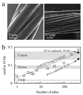
As a comparison, the loss tangents of cotton yarns, nylon 66 yarns, and T300 carbon fibers were also plotted in Figure 4b. The cotton yarns (linear density 55 tex) had the strongest damping performance, with –0.176 (our test results) or even higher than 0.2–0.3 from a recent dynamic mechanical test (linear density 520 tex) qiu.yp:2001 ; qiu.y:2002 . The nylon yarns (linear density 80 tex) exhibited a loss tangent of 0.08–0.098 at 10 Hz (in agreement with other literature reports demsar.a:2010 ) as their structure is more rigid than the cotton yarns. Different from these natural and synthetic yarns, the T300 fiber is a structure even without an interface inside and thus had the weakest damping performance (notice that the carbon fiber bundles did not show measurable increase in loss tangent as their high alignment and high modulus allowed the uniform response to external strain or stress vibrations). Clearly, the multiplying on CNT fibers can efficiently tune the dynamic property within a wide range as changing from carbon fiber to cotton yarn.
CNT fiber is a new man-made synthetic high performance fiber and contains rich interfaces at the nanoscale. The assembly feature introduces frictional energy dissipation and thus a high viscosity. The liquid densification increased the inter-bundle contact and frictional force, but also remarkably suppressed the sliding tendency between CNT bundles. In order to further suppress the sliding tendency, thermosetting polymer resins were infiltrated and cured to form covalent networking within the CNT fiber. This resulted in a extremely low loss tangent, as small as that of Toray carbon fibers. On the contrary, the introduction of thermoplastic polymers introduced new sources for energy dissipation. Finally, when multiple CNT fibers were spun into an agglomeration, the multi-ply CNT yarn, the new inter-fiber contact also became additional energy dissipative interfaces. With considering the high strength, modulus, and flexibility of CNT fibers, we believe that this assembly can be developed as advanced low damping and high quality factor materials.
Experimental Section
Most CNT fibers were produced by the array spinning method zhang.m:2004 ; zhao.jn:2010 ; jia.jj:2011 , where a CNT sheet was pulled out from a vertically aligned CNT array and fabricated under drawing and twisting into a continuous fiber. The twist angle was controlled to range from 15 to 20, by controlling the ratio of drawing and twisting speeds zhao.jn:2010 , and the fiber’s diameter was 13–18 . The CNT arrays used for fiber spinning were synthesized by a sustained chemical vapor deposition on \ceSiO2/Si wafers li.qw:2006 , with synthesis details reported elsewhere li.s:2012 . The grown CNTs were mainly double- to triple-walled and 6 nm in diameter, see also our previous study meng.fc:2014 .
Various strengthening methods were reported for array-spun fibers, such as solvent densification and polymer impregnation fang.c:2010 ; li.s:2012 . In the present study, the array spinning without using any solvent (also called dry spinning), EG densification, PVA and PU infiltrations, and BMI infiltration and curing were used to produce the dry-spun, EG-densified, CNT/PVA, CNT/PU, and CNT/BMI fibers. All the parameters for the infiltration treatment was reported in our previous study li.s:2012 .
Some CNT fibers were produced by twisting and winding a thin CNT film drawn out of a surface where the injection CVD growth was performed li.yl:2004 ; motta.m:2007 ; stano.kl:2008 , and thus were named iCVD fibers. The furnace had a diameter of 40 mm. A mist of ethanol, ferrocene (2 wt%), and thiophene (1 vol%) was injected at a feeding rate of 0.15 ml/min. A gas mixture of Ar and \ceH2 (volume ratio 1:1) was also flowed through the furnace at a rate of 4000 sccm. The reaction was performed at 1300 . The iCVD fibers were mainly composed of double-walled CNTs.
The T150 Universal Testing Machine (Keysight Technologies Inc., Santa Rosa, USA) and the DMA 242 E Artemis (NETZSCH-Gerätebau GmbH, Selb, Germany) were used to characterize the dynamic properties. Frequencies ranging from 10 to 120 Hz were used in the T150 system, and 10–50 Hz in the DMA 242 E Artemis. The vibration amplitude was controlled as load force variation and displacement variation in the two machines respectively. For the T150 system, the default value of mN corresponded to a displacement amplitude of 3–3.5 . The conversion requires the information of fiber diameter , elastic modulus , and gauge length for tensile test, according to such relationship
| (5) |
The temperature was controlled to be 20–25 in the DMA 242 E Artemis.
Acknowledgements
The authors thank financial supports from the National Natural Science Foundation of China (21273269, 11302241, 11404371, 21473238) and Suzhou Industrial Science and Technology Program (ZXG201416).
References
- (1) K. P. Menard, editor, Dynamic Mechanical Analysis: A Practical Introduction, (CRC Press, Boca Raton 1999).
- (2) J. W. S. Hearle, L. Hollick, D. K. Wilson, Yarn Texturing Technology, (CRC Press, Boca Raton 2001).
- (3) K. Jiang, Q. Li, S. Fan, Nature 2002, 419, 801.
- (4) M. Zhang, K. R. Atkinson, R. H. Baughman, Science 2004, 306, 1358.
- (5) Y.-L. Li, I. A. Kinloch, A. H. Windle, Science 2004, 304, 276.
- (6) M. Motta, A. Moisala, I. A. Kinloch, A. H. Windle, Adv. Mater. 2007, 19, 3721.
- (7) J. Jia, J. Zhao, G. Xu, J. Di, Z. Yong, Y. Tao, C. Fang, Z. Zhang, X. Zhang, L. Zheng, Q. Li, Carbon 2011, 49, 1333.
- (8) X. Zhang, Q. Li, in Q. Zhang, editor, Carbon Nanotubes and Their Applications, chapter 14, pages 467–499, (Pan Stanford Publishing, Singapore 2012).
- (9) W. Lu, M. Zu, J.-H. Byun, B.-S. Kim, T.-W. Chou, Adv. Mater. 2012, 24, 1805.
- (10) J. Zhao, X. Zhang, J. Di, G. Xu, X. Yang, X. Liu, Z. Yong, M. Chen, Q. Li, Small 2010, 6, 2612.
- (11) T. Murayama, J. Appl. Polym. Sci. 1979, 24, 1413.
- (12) a) Keysight T150 UTM Data Sheet: literature.cdn.key sight.com/litweb/pdf/5990-4206EN.pdf; b) Continuous Dynamic Analysis Option - Data Sheet: literature.cdn.key sight.com/litweb/pdf/5990-4207EN.pdf; c) Continuous Dynamic Analysis and Quasi-Static Measurement of Spider: literature.cdn.keysight.com/litweb/pdf/5990-4325EN.pdf.
- (13) TORAYCA carbon fibers T300 data sheet: www.toraycfa. com/pdfs/T300DataSheet.pdf.
- (14) S. Li, X. Zhang, J. Zhao, F. Meng, G. Xu, Z. Yong, J. Jia, Z. Zhang, Q. Li, Compos. Sci. Technol. 2012, 72, 1402.
- (15) C. Y. Wei, S. N. Kukureka, J. Mater. Sci. 2000, 35, 3785.
- (16) A. Castellanos-Gomez, N. Agraït, G. Rubio-Bollinger, Nanotechnology 2010, 21, 145702.
- (17) T. Uchiyama, T. Tomaru, D. Tatsumi, S. Miyoki, M. Ohashi, K. Kuroda, T. Suzuki, A. Yamamoto, T. Shintomi, Phys. Lett. A 2000, 273, 310.
- (18) A. Hehr, M. Schulz, V. Shanov, A. Song, J. Intelligent Mater. Systems Structures 2014, 25, 713.
- (19) X. Zhang, K. Jiang, C. Feng, P. Liu, L. Zhang, J. Kong, T. Zhang, Q. Li, S. Fan, Adv. Mater. 2006, 18, 1505.
- (20) Q. Li, X. Zhang, R. F. DePaula, L. Zheng, Y. Zhao, L. Stan, T. G. Holesinger, P. N. Arendt, D. E. Peterson, Y. T. Zhu, Adv. Mater. 2006, 18, 3160.
- (21) K. L. Stano, K. Koziol, M. Pick, M. S. Motta, A. Moisala, J. J. Vilatela, S. Frasier, A. H. Windle, Int. J. Mater. Form. 2008, 1, 59.
- (22) X.-H. Zhong, Y.-L. Li, Y.-K. Liu, X.-H. Qiao, Y. Feng, J. Liang, J. Jin, L. Zhu, F. Hou, J.-Y. Li, Adv. Mater. 2010, 22, 692.
- (23) Q. Liu, M. Li, Y. Gu, Y. Zhang, S. Wang, Q. Li, Z. Zhang, Nanoscale 2014, 6, 4338.
- (24) Y. Li, M. Kröger, Soft Matter 2012, 8, 7822.
- (25) N. Koratkar, B. Wei, P. M. Ajayan, Adv. Mater. 2002, 14, 997.
- (26) N. A. Koratkar, B. Wei, P. M. Ajayan, Compos. Sci. Technol. 2003, 63, 1525.
- (27) J. Suhr, N. Koratkar, P. Keblinski, P. Ajayan, Nat. Mater. 2005, 4, 134.
- (28) C. Fang, J. Zhao, J. Jia, Z. Zhang, X. Zhang, Q. Li, Appl. Phys. Lett. 2010, 97, 181906.
- (29) F. Meng, X. Zhang, R. Li, J. Zhao, X. Xuan, X. Wang, J. Zou, Q. Li, Adv. Mater. 2014, 26, 2480.
- (30) S. Yang, J. Taha-Tijerina, V. Serrato-Diaz, K. Hernandez, K. Lozano, Compos. Part B 2007, 38, 228.
- (31) Y. Qiu, Y. Wang, J. Z. Mi, M. A. Laton, X. Shao, C. Zhang, in National Textile Center Annual Report (2001) page F98-S09.
- (32) Y. Qiu, Y. Wang, M. Laton, J. Z. Mi, Text. Res. J. 2002, 72, 585.
- (33) A. Demšar, V. Bukošek, A. Kljun, Fibres Text. East. Eur. 2010, 18, 29.