gbsn
Coherent optical control of polarization with a critical metasurface
Abstract
We describe the mechanism by which a metamaterial surface can act as an ideal phase-controlled rotatable linear polarizer. With equal-power linearly polarized beams incident on each side of the surface, varying the relative phase rotates the polarization angles of the output beams, while keeping the polarization exactly linear. The explanation is based on coupled-mode theory and the idea of coherent perfect absorption into auxiliary polarization channels. The polarization-rotating behavior occurs at a critical point of the coupled-mode theory, which can be associated with the exceptional point of a parity-time (PT) symmetric effective Hamiltonian.
pacs:
42.25.Bs, 42.25.Ja, 78.67.PtIn photonics, optical loss is commonly regarded as an unwanted nuisance. However, some recent advances have shown that loss is an interesting control parameter in its own right, and can be used to manipulate coherent light in useful ways. A case in point is the phenomenon of coherent perfect absorption (CPA): when the loss in an optical structure is tuned to an appropriate (non-infinite) level, a specific incident wavefront is absorbed without scattering Chong10 ; Wan ; Longhi11 ; Noh ; Zhang ; DuttaGupta ; Pu ; Gutman ; Kang13a ; Kang14 ; Zhang14 . This is a generalization of the phenomenon of “critical coupling” Chong10 , and in a multi-channel system, like a metamaterial surface (“metasurface”) with waves incident from both sides, it provides a way to control light with light without optical nonlinearity Zhang ; DuttaGupta ; Pu : varying part of the incident wavefront, such as the phase of one input beam, can switch the whole wavefront between perfect and near-zero absorption. Another example of optical loss as a control parameter comes from the field of PT symmetric optics, which deals with structures containing spatially-balanced regions of gain and loss Bender ; Bender02 ; Moiseyev ; Guo ; Ruter ; Bittner ; Mostafazadeh ; Longhi09 ; Longhi10 ; Chong11 ; Ge12 ; Lin ; Regensburger ; Castaldi ; Peng . Such devices exhibit an unusual form of non-Hermitian symmetry-breaking Bender , and the “critical point” or “exceptional point” of PT symmetry-breaking Moiseyev has been found to be associated with extraordinary behaviors like unidirectional invisibility Guo ; Ruter ; Bittner ; Mostafazadeh ; Lin ; Regensburger ; Castaldi ; Peng . Intriguingly, several links have been found between PT symmetry and CPA. PT symmetric scatterers can simultaneously exhibit CPA and lasing Longhi09 ; Chong11 ; Ge12 , and in some metasurfaces the occurrence of CPA can be mapped to the PT-breaking transition of an effective Hamiltonian Kang13 .
The theory of CPA is agnostic about the nature of the loss Chong10 , which can be some combination of Ohmic loss, fluorescence—or even radiation into other coherent channels crescimanno ; stone13 . At first glance, treating radiative loss using the language of CPA may seem pointless, for the “absorption” of light from one input channel, and its complete transmission into another channel, occurs in so simple a system as a non-scattering waveguide. However, when there are multiple scattering channels, the CPA concept can provide an interesting method for the coherent manipulation of polarization Wang14 .
The control of polarization with pairs of coherent input beams has been explored in recent experiments by Mousavi et al. Nikolay2014 ; Nikolay2015 , who showed that when two equal-power linearly polarized beams are incident on an appropriately-designed chiral metasurface (e.g. an arrray of asymmetrically-split wire rings), varying the relative phase beween the beams can induce a complete rotation of each output beam’s polarization angle, with the output ellipticity varying by . Hence, the metasurface functions as a phase-controlled polarization rotator. To explain this, Mousavi et al. noted that, for a single input beam, the transmission is approximately circularly polarized; say, left-circularly polarized (LCP). To explain the polarization rotation, the reflection of the other input beam, incident from the opposite side, must be right-circularly polarized (RCP). This implies, by mirror symmetry, that for each input beam the reflection and transmission have the same handedness. This seems counter-intuitive, for a chiral resonance with mirror symmetry along the propagation axis ought to emit to each side with opposite handedness.
In this paper, we present a theoretical study of an ideal two-sided polarization-rotating metasurface, which reveals deep ties to the concepts of CPA Chong10 ; Wan ; Longhi11 ; Noh ; Zhang ; DuttaGupta ; Pu ; Gutman ; Kang13a ; Kang14 ; Zhang14 and PT symmetry Bender ; Bender02 ; Moiseyev ; Guo ; Ruter ; Bittner ; Mostafazadeh ; Longhi09 ; Longhi10 ; Chong11 ; Ge12 ; Lin ; Regensburger ; Castaldi ; Peng ; Kang13 . The metasurface, differing from Refs. Nikolay2014 ; Nikolay2015 , contains pairs of coupled resonators radiating into different linear polarization channels. Using coupled-mode theory R21 ; R22 ; R23 ; R24 ; R25 ; R26 ; R27 , we show that when linearly polarized input beams are incident on each side, achieving perfect conversion to the other polarization (i.e., rotation) requires a specific balance between radiative and non-radiative loss rates; this is analogous to ordinary CPA, which occurs at specific intrinsic loss levels Chong10 . For special “critical” choices of the frequency and loss parameters, the output beams become exactly linearly polarized for all values of the relative input phase , with polarization angles varying with . Under one-sided illumination, the reflected and transmitted beams have the same handedness, which results from interference between direct and indirect transmission processes. However, the critical metasurface is generally not a perfect circular polarizer under one-sided illumination, and the simple explanation involving phase-shifted RCP and LCP components Nikolay2014 ; Nikolay2015 holds only in the limit where the radiative and inter-resonator near-field coupling rates dominate the dissipative loss rate, and the total loss is negligible. Nonetheless, when two input beams are applied, the elliptically polarized reflection and transmission on each side combine to give zero total ellipticity. The critical points of the coupled mode theory, where this behavior occurs, are the PT-breaking points of a non-Hermitian effective Hamiltonian, whose eigenvalues give the frequencies for the CPA-like perfect polarization conversion condition. (Similar mappings to PT symmetric Hamiltonians have previously been explored for CPA Kang13 , and for polarization conversion under one-sided transmission Lawrence .) Using other parameters choices, we can also switch the outputs between circular and linear polarization by varying . We present full-wave simulation results verifying the predictions of the coupled-mode theory.
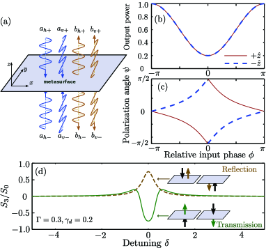
Consider the plane metasurface depicted in Fig. 1(a), which is mirror-symmetric along the direction normal to the plane. The metasurface is populated by pairs of coupled resonant modes, described by amplitudes , which radiate in the and directions respectively. Plane waves are normally incident on the metasurface from both directions, with wave amplitudes , where denotes waves incident from the top (bottom) of the plane, and denotes the linear polarization component parallel to the direction. Likewise, the waves leaving the metasurface are described by amplitudes , with denoting waves exiting in the directions. The coupling between the metasurface resonances and the input/output waves is described by a set of coupled-mode equations R21 ; R22 ; R23 ; R24 ; R25 ; R26 ; R27 :
| (1a) | ||||
| (1b) | ||||
where
| (2a) | ||||
| (2b) | ||||
| (2c) | ||||
Here, (where ) is the detuning of the operating frequency from the -oriented mode, is the radiative scattering rate, is the non-radiative dissipation rate, and is the near-field coupling between the modes; all these parameters are real. The matrix represents the radiative coupling between the metasurface and the input/output waves, while represents the direct coupling between the waves. The forms of these matrices are constrained by the mirror symmetry of the metasurface, the definitions of energy and power in terms of the coupled-mode quantities, and optical reciprocity R22 . The scattering matrix , defined by , takes the form
| (3) |
The sub-matrix () describes how light incident in the polarization scatters into the same polarization, while describes the cross-polarized scattering.
We now assume that the metasurface is designed so the resonances have the same dissipation rates and frequencies:
| (4) |
(The radiative scattering rates, however, can and will differ.) Furthermore, we consider purely -polarized incident illumination, with input amplitudes . The outputs in each polarization are and . Due to the mirror symmetry, has a symmetric eigenvector and an antisymmetric eigenvector ; the latter, with eigenvalue , corresponds to a node on the plane, and hence zero total loss.
By varying the metasurface parameters and input amplitudes, it is possible to arrive at a situation where , i.e. all the -polarized incident light is re-emitted in the polarization and/or dissipated. This corresponds to CPA with -polarized emission as one of the “absorption” channels (it would be “ordinary” CPA if ). For this to occur, the symmetric eigenvector of must have eigenvalue zero, and we can show that this occurs if and only if
| (5a) | ||||
| (5b) | ||||
We can satisfy Eq. (5a) by designing each resonator appropriately, as discussed below. Then if , perfect polarization conversion can occur at two distinct frequencies. But if , Eq. (5b) cannot be satisfied for any .
We can interpret the conditions (5a)–(5b) in terms of an effective Hamiltonian, via an argument from Ref. Kang13 . From Eq. (3), we write , where
| (6) |
The eigenvalues of are the detunings for which . These detunings should be real, but is non-Hermitian. However, becomes PT symmetric Bender , with and the complex conjugation operation, when Eq. (5a) is satisfied. In that case, the eigenvalues of are , which are the solutions to Eq. (5b); then the eigenvalues are real for the PT-unbroken phase of , . In the PT-broken phase, , perfect polarization conversion cannot occur for any real . At , which are the critical points of Eq. (5b) and the PT-breaking exceptional points Moiseyev of , perfect polarization conversion occurs at only one detuning, .
Now suppose the metasurface is tuned to one of the critical points, satisfying Eqs. (5a)–(5b) with , . For -polarized inputs, the coupled-mode equations give
| (7) | ||||
| (8) |
The outputs have equal power, and third Stokes parameters
| (9) |
Hence, for equal-power inputs (), both outputs are exactly linearly polarized ().
Part of this result is easy to understand: the outputs are -polarized for symmetric inputs (perfect polarization conversion), and -polarized for antisymmetric inputs (node on the plane). However, Eq. (9) goes further, and states that the output beams are linearly polarized for any choice of input beam phases. Varying the relative phase rotates the output beams’ polarization angles between . This behavior is specific to the critical metasurface. (At the other critical point, , Eqs. (8) and (9) have opposite signs, and the phase shift rotates the polarization in the opposite direction. Thus, implies broken left-right symmetry on the metasurface.)
The action of the critical metasurface as a rotatable linear polarizer is shown in Fig. 1(b)–(c). At , perfect polarization conversion occurs, and the power of each output beam reaches a minimum of due to dissipation. If the dissipation is weak, , the total loss is , and the polarization angle relative to the axis is for the outputs in the direction.
To better understand the critical behavior, we examine the reflection and transmission under one-sided -polarized illumination. As shown in Fig. 1(d), for reflection and for transmission at the critical point, for either choice of input direction. From the definition of , this means that a single input beam produces reflected and transmitted beams with the same handedness. This is because the transmission is comprised of direct transmission of the linearly-polarized input, and re-emission from the metasurface resonators. At the critical point, the total transmission’s handedness is opposite to the re-emitted component, and the same as the reflected beam. Fig. 1(d) also shows that the transmission and reflection are not exactly circularly polarized for , but these elliptically polarized components are nonetheless able to combine to form linearly polarized output beams.
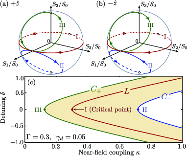
Away from the critical point, the metasurface ceases to act as a linear polarizer under equal-power incident beams, as each output beam becomes elliptically polarized. However, there is a remnant of the critical behavior, due to the winding behavior on the Poincaré sphere. Right at the critical point, one cycle of winds each output amplitude along the equator of the Poincaré sphere, as depicted by the red loops in Fig. 2(a)–(b). Away from the critical point, the trajectory no longer follows the equator exactly, but one complete cycle of still induces one winding of the longitudinal angle —and hence a full rotation of the angle of the polarization ellipse’s semi-major axis, . This is true so long as the loops do not cross the poles (where the output beams become circularly polarized). It can be shown that the pole-crossings occur when
| (10) |
For , the signs correspond to an RCP (LCP) output and an LCP (RCP) output. This results in the “phase diagram” shown in Fig. 2(c). The solutions to Eq. (10) lie along the curves labeled . In the region between these two curves, the longitudinal angle undergoes a complete winding with . The behavior for can be similarly deduced. When Eq. (10) is satisfied, varying switches the output between linear polarization and circular polarization, as shown by the green and blue curves in Fig. 2(a)–(b).
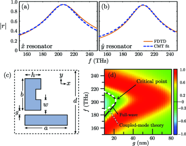
We have verified the above coupled-mode theory using numerical simulations of an exemplary plasmonic metasurface, shown schematically in Fig. 3(c). Each unit cell contains a silver strip antenna radiating in the direction, and a silver split-ring resonator (SRR) radiating in . The cells are arranged in a square lattice with period nm, and the entire metasurface is free-standing in vacuum, which guarantees that no high-order diffraction mode exists below THz. The dielectric function of silver is modeled by a Drude formula , where THz, THz, and . To extract the coupled-mode parameters for each resonator, we perform full-wave (finite-difference time-domain) numerical simulations of single-sided illumination incident on each antenna separately, in the absence of the other antenna, with the appropriate linear polarization. The computed reflectance spectrum is fitted to the theoretical result obtained from Eqs. (1b)–(2c) in the limit. Using the parameters stated in the caption of Fig. 3, the resonators have equal resonance frequencies THz and dissipation rates THz, thus satisfying Eq. (4). Furthermore, the radiative decay rates are THz and THz, satisfying Eq. (5a).
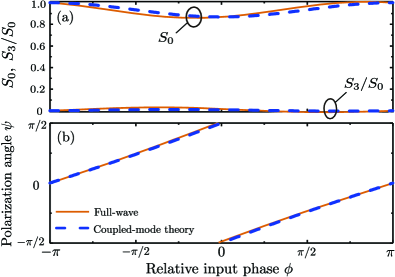
We then include both resonators in the metasurface, separated by distance , and perform another set of full-wave simulations. Varying , with all other geometrical parameters fixed, alters the near-field coupling parameter , as well as (weakly) the resonant frequency . Nonlinear fits of the simulation results to the coupled-mode theory give the functional relations , where and have units of THz and nm, and in THz. The fitted coupled-mode theory gives results for the various output Stokes parameters that agree well with the simulation results. For instance, Fig. 3(d) shows the simulation results of for one of the output beams, with a pair of symmetric input beams. The locus of according to the simulation (black line) closely matches coupled-mode prediction (white dashes). Using Eq. (5b), we find that the critical point occurs at nm, THz. Fig. 4 shows the behavior at this critical point, which is in good agreement with the coupled-mode theory, particularly in the fact that for all .
In summary, we have shown that the principles of CPA and PT symmetry can be used to design metasurfaces for coherently manipulating polarization using two input beams. This is an example of an emerging class of photonic devices that exploit the properties of “critical points” or “exceptional points” Lin ; Peng ; Rotter12 ; Rotter14 . Here, the critical behavior corresponds to the output beams achieving exactly zero ellipticity. With other choices of metasurface parameters, other forms of polarization control can be achieved, such as switching between circular and linear polarization. Generalizations of the coupled-mode theory, such as having resonators which are not exclusively coupled to a single linear polarization channel, might be useful for designing other classes of polarization-controlling metasurfaces.
M. Kang acknowledges supports from the National Natural Science Foundation of China under Grant 11304226, and the China Postdoctoral Science Foundation under Grant No. 2014M560414. Y. D. Chong acknowledges support from the Singapore National Research Foundation under Grant No. NRFF2012-02, and from the Singapore MOE Academic Research Fund Tier 3 Grant MOE2011-T3-1-005. We are grateful to N. I. Zheludev, R. Singh, C. Altuzarra, and S. Vezzoli for helpful discussions and comments.
References
- (1) Y. D. Chong, L. Ge, H. Cao, and A. D. Stone, Phys. Rev. Lett. 105, 053901 (2010).
- (2) W. Wan, Y. D. Chong, L. Ge, H. Noh, A. D. Stone, and H. Cao, Science 331, 889 (2011).
- (3) S. Longhi, Phys. Rev. A 83, 055804 (2011).
- (4) H. Noh, Y. D. Chong, A. D. Stone, and H. Cao, Phys. Rev. Lett. 108, 186805 (2012).
- (5) J. Zhang, K. F. MacDonald, and N. I. Zheludev, Light: Sci. Appl. 1, e18 (2012).
- (6) S. Dutta-Gupta, O. J. Martin, S. D. Gupta, and G. S. Agarwal, Opt. Ex. 20, 1330 (2012).
- (7) M. Pu, Q. Feng, M. Wang, C. Hu, C. Huang, X. Ma, Z. Zhao, C. Wang, and X. Luo, Opt. Ex. 20, 2246 (2012).
- (8) N. Gutman, A. A. Sukhorukov, Y. D. Chong, and C. M. de Sterke, Opt. Lett. 38, 4970 (2013).
- (9) M. Kang, F. Liu, T. Li, Q. Guo, J. Li, and J. Chen, Opt. Lett. 38, 3086 (2013).
- (10) M. Kang, Y. D. Chong, H.-T. Wang, W. Zhu, and M. Premaratne, Appl. Phys. Lett. 105, 131103 (2014).
- (11) J. Zhang, C. Guo, K. Liu, Z. Zhu, W. Ye, X. Yuan, and S. Qin, Opt. Ex. 22, 12524 (2014).
- (12) C. M. Bender and S. Boettcher, Phys. Rev. Lett. 80, 5243 (1998).
- (13) C. M. Bender, M. V. Berry, and A. Mandilara, J. Phys. A 35, L467 (2002).
- (14) S. Klaiman, U. Günther, and N. Moiseyev, Phys. Rev. Lett. 101, 080402 (2008).
- (15) A. Guo, G. J. Salamo, D. Duchesne, R. Morandotti, M. Volatier-Ravat, V. Aimez, G. A. Siviloglou, and D. N. Christodoulides, Phys. Rev. Lett. 103, 093902 (2009).
- (16) C. E. Rüter, K. G. Makris, R. El-Ganainy, D. N. Christodoulides, M. Segev, and D. Kip, Nat. Phys. 6, 192 (2010).
- (17) S. Bittner, B. Dietz, U. Gunther, H. L. Harney, M. Miski-Oglu, A. Richter, and F. Schafer, Phys. Rev. Lett. 108, 024101 (2012).
- (18) A. Mostafazadeh, Phys. Rev. Lett. 102, 220402 (2009).
- (19) S. Longhi, Phys. Rev. Lett. 103, 123601 (2009).
- (20) S. Longhi, Phys. Rev. A 82, 031801(R)(2010).
- (21) Y. D. Chong, L. Ge, and A. D. Stone, Phys. Rev. Lett. 106, 093902 (2011).
- (22) L. Ge, Y. D. Chong and A. D. Stone, Phys. Rev. A 85, 023802 (2012).
- (23) Z. Lin, H. Ramezani, T. Eichelkraut, T. Kottos, H. Cao, and D. N. Christodoulides, Phys. Rev. Lett. 106, 213901 (2011).
- (24) A. Regensburger, C. Bersch, M.-A. Miri, G. Onishchukov, D. N. Christodoulides, and U. Peschel, Nature (London) 488, 167 (2012).
- (25) G. Castaldi, S. Savoia, V. Galdi, A. Alú, and N. Engheta, Phys. Rev. Lett. 110, 173901 (2013).
- (26) B. Peng, Ṣ. K. özdemir, F. Lei, F. Monifi, M. Gianfreda, G. L. Long, S. Fan, F. Nori, C. M. Bender, and L. Yang, Nat. Phys. 10, 394 (2014).
- (27) M. Kang, F. Liu, J. Li, Phys. Rev. A 87, 053824 (2013).
- (28) M. Crescimanno, N. J. Dawson, and J. H. Andrews, Phys. Rev. A 86, 031807(R) (2012).
- (29) Y. D. Chong, H. Cao, and A. D. Stone, Phys. Rev. A 87, 013843 (2013).
- (30) Y. Wang, M. Pu, C. Hu, Z. Zhao, C. Wang, and X. Luo, Opt. Comm. 319, 14 (2014).
- (31) S. A. Mousavi, E. Plum, J. Shi, and N. I. Zheludev, Appl. Phys. Lett. 105, 011906 (2014).
- (32) S. A. Mousavi, E. Plum, J. Shi, and N. I. Zheludev, Sci. Rep. 5, 8977 (2015).
- (33) H. A. Haus, Waves and Fields in Optoelectronics(Prentice-Hall, Englewood Cliffs, NJ, 1984).
- (34) W. Suh, Z. Wang, and S. Fan, IEEE J. Quantum Electron. 40, 1511 (2004).
- (35) R. E. Hamam, A. Karalis, J. D. Joannopoulos, and M. Soljacic, Phys. Rev. A 75, 053801 (2007).
- (36) S. Zhang, D. A. Genov, Y. Wang, M. Liu, and X. Zhang, Phys. Rev. Lett. 101, 047401 (2008).
- (37) N. Liu, L. Langguth, T. Weiss, J. Kästel, M. Fleischhauer, T. Pfau, and H. Giessen, Nature Mater. 8, 758(2009).
- (38) L. Verslegers, Z. Yu, Z. Ruan, P. B. Catrysse, and S. Fan, Phys. Rev. Lett. 108, 083902(2012).
- (39) P. Tassin, L. Zhang, R. Zhao, A. Jain, T. Koschny, and C. M. Soukoulis, Phys. Rev. Lett. 109, 187401(2012).
- (40) M. Lawrence, N. Xu, X. Zhang, L. Cong, J. Han, W. Zhang, and S. Zhang, Phys. Rev. Lett. 113, 093901 (2014).
- (41) M. Liertzer, L. Ge, A. Cerjan, A. D. Stone, H. E. Türeci, and S. Rotter, Phys. Rev. Lett. 108, 173901 (2012).
- (42) M. Brandstetter, M. Liertzer, C. Deutsch, P. Klang, J. Schöberl, H. E. Türeci, G. Strasser, K. Unterrainer, and S. Rotter, Nature Comm. 5, 4034 (2014).