Muon Emittance Exchange with a Potato Slicer
D. J. Summers, T. L. Hart, J. G. Acosta, L. M. Cremaldi,
S. J. Oliveros, and L. P. Perera
University of Mississippi - Oxford, University, MS 38677 USA
D. V. Neuffer
Fermilab, Batavia, IL 60510 USA
MAP-DOC - 4405, Apr 2015
Abstract
We propose a novel scheme for final muon ionization cooling with quadrupole doublets followed by emittance exchange in vacuum to achieve the small beam sizes needed by a muon collider. A flat muon beam with a series of quadrupole doublet half cells appears to provide the strong focusing required for final cooling. Each quadrupole doublet has a low beta region occupied by a dense, low Z absorber. After final cooling, normalized transverse, longitudinal, and angular momentum emittances of 0.100, 2.5, and 0.200 mm-rad are exchanged into 0.025, 70, and 0.0 mm-rad. A skew quadrupole triplet transforms a round muon bunch with modest angular momentum into a flat bunch with no angular momentum. Thin electrostatic septa efficiently slice the flat bunch into 17 parts. The 17 bunches are interleaved into a 3.7 meter long train with RF deflector cavities. Snap bunch coalescence combines the muon bunch train longitudinally in a 21 GeV ring in 55 s, one quarter of a synchrotron oscillation period. A linear long wavelength RF bucket gives each bunch a different energy causing the bunches to drift in the ring until they merge into one bunch and can be captured in a short wavelength RF bucket with a 13% muon decay loss and a packing fraction as high as 87 %.
| (mm) | (mm) | (mm) | (mm3) | Ref. | |
|---|---|---|---|---|---|
| Emittance after Phase Rotation | 48.6 | 48.6 | 17.0 | 40,200 | [4] |
| Helical Cooling Channel | 0.523 | 0.523 | 1.54 | 0.421 | [3] |
| Rectlinear Cooling Channel | 0.28 | 0.28 | 1.57 | 0.123 | [4] |
| Muon Collider | 0.025 | 0.025 | 70 | 0.044 | [1] |
| z(m) | 0.000 | 0.016 | 0.030 | 0.092 | 0.183 | 0.402 | 0.625 | 0.717 | 0.779 | 0.793 | 0.806 |
|---|---|---|---|---|---|---|---|---|---|---|---|
| (cm) | 3.08 | 3.93 | 5.92 | 26.16 | 42.64 | 33.75 | 42.64 | 26.16 | 5.92 | 3.93 | 3.10 |
| (mm) | 2.11 | 2.39 | 2.93 | 6.16 | 7.86 | 7.00 | 7.86 | 6.16 | 2.93 | 2.39 | 2.12 |
| (mrad) | 68.6 | 60.7 | 49.5 | 23.5 | 18.4 | 20.7 | 18.4 | 23.5 | 49.5 | 60.7 | 68.4 |
| Material | Density | LR | dE/ds | (equilibrium) |
|---|---|---|---|---|
| g/cm3 | cm | MeV/cm | mm - rad | |
| H2 gas | 0.000084 | 750,000 | 0.00037 | 0.036 |
| Li H | 0.82 | 97 | 1.73 | 0.059 |
| Be | 1.85 | 35.3 | 3.24 | 0.087 |
| B4C | 2.52 | 19.9 | 4.57 | 0.109 |
| Diamond | 3.52 | 12.1 | 6.70 | 0.123 |
| Be O | 3.01 | 13.7 | 5.51 | 0.132 |
Introduction
Due to s-channel production, a muon collider [1] may be ideal for the examination of H/A Higgs scalars which could be at the 1.5 TeV/c 2 mass scale and are required in supersymmetric models [2]. But what is the status of muon cooling? As noted in Table 1, more than five orders of magnitude of muon cooling have been shown in two simulated designs [3, 4] but not quite the six orders of magnitude needed for a high luminosity muon collider. Also as noted in Table 1, some of the longitudinal cooling needs to be exchanged for lower transverse emittance.
The breakdown of RF cavities operating in strong magnetic fields is an issue [6]. The Helical Cooling Channel inhibits breakdown with high pressure hydrogen [7]. Hydrogen at moderate pressures, lower than those used in interstate natural gas pipelines, may work for the Rectilinear Cooling Channel [8]. As seen in Table 2, the Rectlinear Cooling Channel does have some high regions, but these only cause minimal heating if hydrogen pressure is modest [9].
An infinite solenoid [10] with a 14 Tesla magnetic field and a 200 MeV/c muon beam gives a betatron function of = 9.5 cm. As noted in Table 2, the short solenoids in the final stage of the Rectilinear Cooling Channel give a betatron function of 3.1 cm which is used with lithium hydride. To possibly get to the lower betatron values of about 1 cm needed by a muon collider for final cooling [11], quadrupole doublet cells are explored in Appendix Z. Table 3 gives transverse equilibrium emittances for a number of low Z materials, particularly those with high densities.
Round to Flat Beam Transformation
Assume that a muon beam with a normalized transverse emittance of 0.100 mm is available. Further assume that the beam has some modest and smooth residual angular momentum coming out of a 6D cooling channel. The beam does pick up canonical angular momentum as it passes though absorbers in solenoids.
First, a round spinning muon beam with angular momentum is transformed to a flat non-spinning beam with a skew quadrupole triplet [14] as shown in Fig. 1. This should make slicing easier. The to emittance ratio of the flat beam is , where is the intrinsic normalized transverse emittance, is the quadrature emittance contribution of the canonical angular momentum, is the solenoidal field strength that the beam is exiting, and is the round beam radius. is chosen to give an emittance ratio of 16 for a beam with new nominal transverse normalized emittances of 0.0264 mm and 0.4206 mm. The muon momentum is 20010 MeV/c. Higher momentum spreads dilute performance, but beam preconditioning may help [15].
Slice the Flat Beam with 16 Septa
| Number | Number of | RF | RF | Output | Output | |
|---|---|---|---|---|---|---|
| Tier | of Trains | RF Deflector | Frequency | Wavelength | Spacing in | Bunch |
| Interleaving | Cavities | MHz | Wavelengths | Spacing | ||
| 1 | 17 6 | 6 | (9/16)1300 = 731 | 410 mm | 9/4 | 923 mm |
| 2 | 6 2 | 3 | (3/8)1300 = 487 | 616 mm | 3/4 | 462 mm |
| 3 | 2 1 | 1 | (1/2)1300 = 650 | 462 mm | 1/2 | 231 mm |
Slice [16] the flat muon beam into 17 pieces. The slice width is chosen to give a horizontal emittance of 0.025 mm-rad and includes 91% of the muons; 9% of the muons are in the tails and lost. A 0.1 mm wide electrostatic septa was used with 98% efficiency at the Fermilab Tevatron fixed target program for multiturn extraction. At the Tevatron the fractional loss was given by
| (1) |
where is the beam size with the usual of the lattice and a larger function, , is used in the extraction region to make the beam bigger. The physical width of the muon beam is
| (2) |
giving a modest 3% slicing loss. The geometrical width of the beam needs to be much larger than the width of the electrostatic septa for efficient slicing.
Create a 3.7 m long bunch train with RF deflector cavities
Combine 17 bunches into a 3.7 m long train with RF deflector cavities as used in CLIC tests. Each cavity interleaves two or three bunch trains. Deflection is 4.5 mrad or zero at 300 MeV/c [18]. The final train has a 231 mm bunch spacing for acceleration by 1300 MHz RF cavities (see Table 4). Estimate the required kick [19] to inject a 300 MeV/c ( = 300/105.7 = 2.84) beam with a normalized emittance of 0.025 mm-rad and a of 8000 mm. The kick must be 4x greater than the rms divergence of the beam or 4 = 4.2 mrad, which matches CLIC. The beam diameter is 8 = 67 mm.
Snap bunch coalesce a train of 17 bunch into one in a ring
Finally, snap bunch coalescing with RF is used to combine the 17 muon bunches longitudinally. In snap bunch coalescing, all bunches are partially rotated over a quarter of a synchrotron period in energy-time space with a linear long wavelength RF bucket and then the bunches drift in a ring until they merge into one bunch and can be captured in a short wavelength RF bucket. The bunches drift together because they each have a different energy set to cause the drift. Snap bunch coalescing replaced adiabatic bunch coalescing at the Fermilab Tevatron collider program and was used for many years [20]. Sets of fifteen bunches were combined in the Tevatron. A 21 GeV ring has been used in a simulation [21] with ESME [22] to show the coalescing of 17 muon bunches in 55 s. The lattice has = 5.6 [23]. The muon decay loss is 13%. The longitudinal packing fraction is as high as 87% [24]. So nominally, the initial normalized 2.5 mm longitudinal emittance is increased by a factor of 17/0.87 to become 49 mm, which is less than the 70 mm needed for a muon collider.
Conclusions
Emittance exchange with a potato slicer may be able to achieve the final normalized 0.025 mm transverse and 70 mm longitudinal emittances needed for a high luminosity muon collider,
| (3) |
where is average luminosity, is the initial number of muons per bunch (one positive and one negative), is the collision frequency (two detectors), is the duty cycle with a 15 Hz repetition rate, and is the betatron function in the collision region. The initial 6D emittance must be small enough, the potato slicer does not cool muons. The longitudinal emittance is as large as can be tolerated by the chromaticity requirement [25] of a 1.5 TeV/c 2 muon collider final focus with round 750 GeV beams, = 0.99999999, = E/mμ, and a 10 mm long collision region.
| (4) |
Acknowledgements
Many thanks to Yuri Alexahin, Chuck Ankenbrandt, Scott Berg, Chandra Bhat, Alex Bogacz, Moses Chung, Mary Anne Cummings, Jean-Pierre Delahaye, Ben Freemire, Carol Johnstone, Trey Lyons, Bob Palmer, Mark Palmer, Philippe Piot, Tom Roberts, Robert Ryne, Hisham Sayed, Pavel Snopok, Diktys Stratakis, Mike Syphers, Yagmur Torun, and Katsuya Yonehara for many useful conversations.
Appendix A: Skew quadrupole triplet algebra
Define magnetic normalized emittance as
.
Define transverse intrinsic normalized emittance as
which assumes and .
When exiting solenoid, is transformed to
with and
Define .
The relationship between the quadrupole focal length and integrated magnetic field is

Appendix B: Skew Quadrupole Triplet for a Large Emittances.
The emittance exchange of a large 50 mm transverse emittance beam is simulated. Parameters are chosen (see Fig. 2) to give an ideal emittance ratio of 16. The actual new nominal transverse normalized emittances are 13 mm and 295 mm. Round to flat beam transformations may have many uses. A beam with a low emittance in one dimension might be spread with a dipole to separate isotopes [27].
Appendix C: Deflecting RF Transverse to Longitudinal Exchange
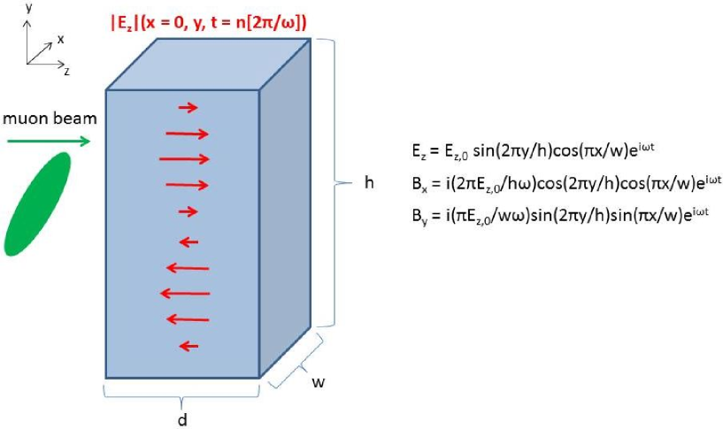
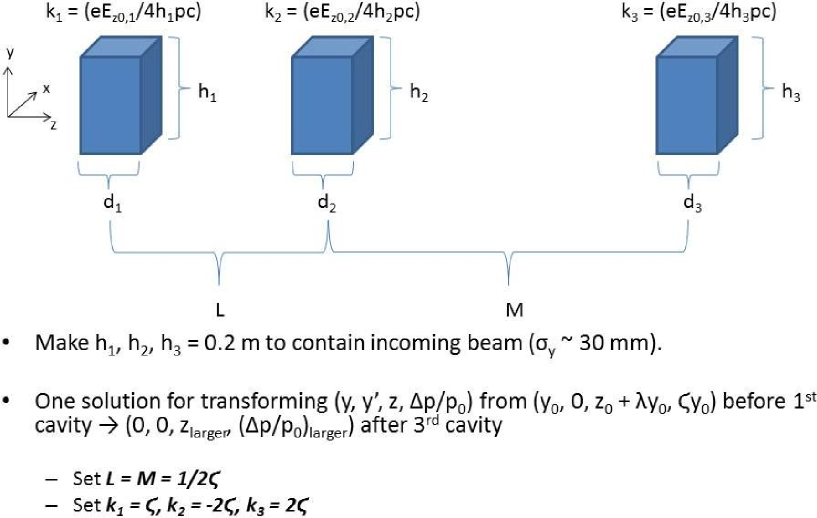
We explore the possibility of using deflecting RF cavities to transfer transverse emittance to longitudinal emittance. The desired normalized emittance transfer is m so that () is (decreased/increased) by a factor of 16. would be kept at 25 m. Figure 3 shows a schematic diagram of a box RF deflecting cavity. The inital muon momentum is roughly 200 10 MeV/c, and the Gaussian beam position spread in is 30 mm. Transforming the and longitundinal normalized emittances by a factor of 16 with deflecting RF cavities involves increasing the beam momentum spread 16-fold to 160 and establishing a correlation between and the momentum. As this treatment is very approximate, the longitudinal quantity will be defined as so that the following derivations may be missing a factor or two of which is 0.884 for a 200 muon.
An algorithm [28] is used for determining the optics of a triplet of deflecting RF cavities that will enact the transvere-longitudinal emittance transformation. Figure 4 shows the layout of a triplet of RF deflecting cavities.
There are an infinite number of solutions, and section VI -A of [28] includes a solution in which the three deflecting RF cavities are equally spaced and the normalized strength of the first deflecting RF cavity, , is set equal to the correlation ratio between the energy deviation and the transverse position, . Defining the normalized strengths of the deflecting RF cavites as , , and and the distances between the deflecting RF cavities as :
(first deflecting RF cavity)
(second deflecting RF cavity)
(third deflecting RF cavity)
(distances between RF cavities)
Distances and strengths of the RF cavities will be now be worked out, which has (160/200)/(0.03 m) = 26.7/m. Then, L = distance between cavities = 1/(2 26.7/m) = 0.01875 m. To capture the beam with , the deflecting RF cavity should be about h = total height = 0.2 m tall. The longitudinal electric field in a box deflecting RF cavity with total height (along ) and total width (along ) is
Also, the total length, , of deflecting RF cavites should be a fraction of the separation between the cavities, so that we can set = total cavity length = 0.01 m. Also, so that = 0.02 m and = 15 GHz. Finally, the normalized strength, of a deflecting RF cavitiy is related to through where and are the total length and total width of the deflecting RF cavity respectively. For and ,
Ez,0 = 432,000 MV/m for the first deflecting RF cavity,
Ez,0 = -864,000 MV/m for the second deflecting RF cavity,
Ez,0 = 864,000 MV/m for the third deflecting RF cavity.
The electric fields gradients required appear to be vastly too high to perform a transverse to longitudinal exchange for large emittances.
Appendix Z: Quadrupole Doublet Focusing for Final Muon Cooling
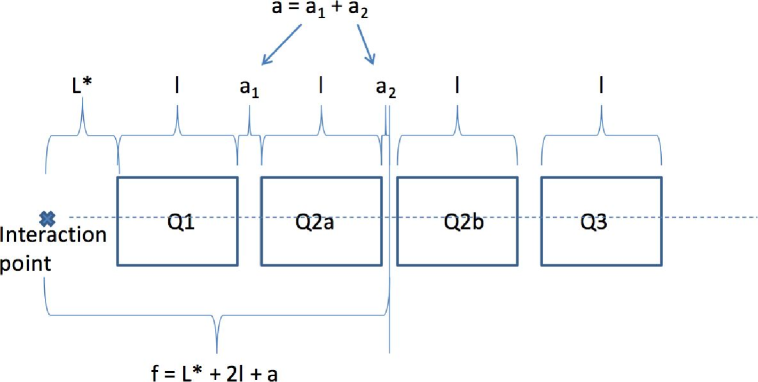
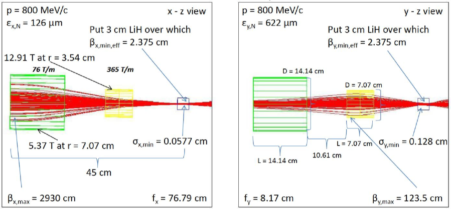
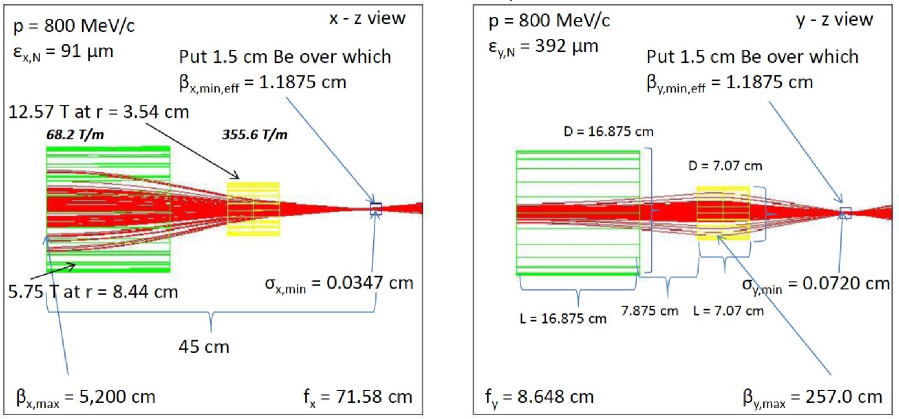
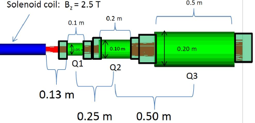
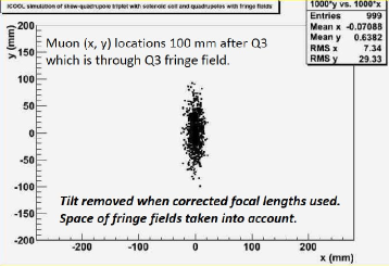
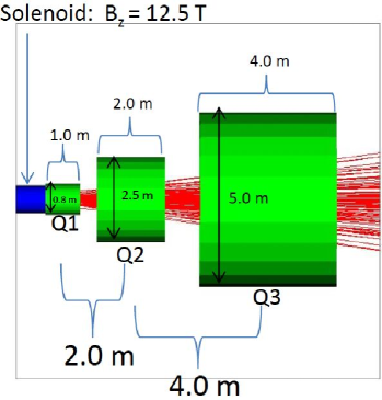
Following Feher and Strait [29] and their paper on hadron collider final focus quadrupole triplet design in 1996 with a of 50 cm, we look into a short quadrupole doublet for final muon cooling with a of 1 cm. Focal lengths in x and y are not the same in the doublet. The LHC inner triplet is composed of four identical 5.5 m long quadrupoles as shown in Figure 5. The outer two quadrupoles are focusing in the first transverse dimension and defocusing in the second transverse dimension. The inner two quadrupoles are focusing in the second transverse dimension and defocusing in the first transverse dimension. Add 0.3 m for trim coils and take a quadrupole length, , of 5.8 m. The focusing strength to be proportional to the lengths of the four quadrupoles 4, times field gradient G in T/m, times focal length (Lf = L∗ + 2 + ) in meters, divided by beam momentum in TeV/c. L∗ is the distance from the interaction point to the front of the first quadrupole and is additional length for magnet interconnections. The focal length is just the distance from the interaction point to the center of the quadrupole triplet as shown in Figures 6 and 7. The relation between functions and the focal length is given by , where b is a fudge factor equal to 1.65 for the LHC.
A short length of low Z absorber absorber is placed at the focus of each quadrupole doublet as shown in Figures 6 and 7. Flat beams are used with the quadrupole doublets which do not exceed 14 T as in the LHC Nb3Sn LARP quadrupoles [30]. Note that . As becomes smaller, the absorber must become thinner in the beam direction , so one may want to employ beryllium or diamond. The fringe fields of the magnet fall off as the cube of distance [31] and may be small enough to not cause breakdown even in vacuum RF. The beam power of 800 MeV/c muons (KE = 701 MeV) arriving at 15 Hz is 6700 watts of which only a tiny fraction would heat the superconductor even in the absence of shielding.
In summary, quadrupole doublets and dense, low Z absorbers are being examined to cool the current outputs given either by the Helical [3] or Rectilinear [4] 6D muon cooling channels and prepare the input for the potato slicer which reduces the normalized transverse beam emittance to the 25 m size required by a high luminosity muon collider. A more complete simulation of a tapered quadrupole doublet channel is in progress.
References
-
[1]
G. Budker, Conf.Proc. C690827 (1969) 33;
A. N. Skrinsky, Morges 1971, AIP Conf. Proc. 352 (1996) 6;
D. V. Neuffer and R. B. Palmer, EPAC 94, BNL - 61267;
D. J. Summers, Bull. Am. Phys. Soc. 39 (1994) 1818;
R. Palmer et al., Nucl. Phys. Proc.Suppl. 51A (1996) 61;
C. M. Ankenbrandt et al., Phys. Rev. ST Accel. Beams 2 (1999) 081001;
M. M. Alsharo’a et al., Phys. Rev. ST Accel. Beams 6 (2003) 081001;
R. B. Palmer et al., PAC 07, arXiv:0711.4275. - [2] E. Eichten and A. Martin, Phys. Lett. B728 (2014) 125.
-
[3]
C. Yoshikawa et al., IPAC -2014 -TUPME016;
Y. Derbenev and R. P. Johnson, Phys. Rev. ST Accel. Beams 8 (2005) 041002. -
[4]
D. Stratakis et al., IPAC -2014 -TUPME020;
D. Stratakis et al., Phys. Rev. ST Accel. Beams 18 (2015) 044201;
D. Stratakis and R. B. Palmer, Phys. Rev. ST Accel. Beams 18 (2015) 031003;
V. Balbekov, MAP- DOC - 4365 (2013);
D. Stratakis et al., Phys. Rev. ST Accel. Beams 16 (2013) 091001;
R. B. Palmer et al., Phys. Rev. ST Accel. Beams 8 (2005) 061003. - [5] Diktys Stratakis, private communication.
- [6] A. Moretti et al., LINAC 04, Conf.Proc. C0408164 (2004) 271.
-
[7]
M. Chung et al., Phys. Rev. Lett. 111 (2013) 184802;
B. Freemire et al., IPAC -2014 -THPRI064;
D. Neuffer and K. Paul, EPAC -2006 -WEPLS012. -
[8]
D. Stratakis, IPAC - 2014 - TUPME024;
J. C. Gallardo and M. S. Zisman, AIP Conf. Proc. 1222 (2010) 308. -
[9]
K. Yonehara,
“Emittance growth by gas in a hybrid channel (preliminary),”
13 Jan 2015, MAP D&S Meeting,
https://indico.fnal.gov/conferenceDisplay.py?confId=9267 - [10] J. C. Gallardo et al., Snowmass 96, BNL - 52503, pp. 245 -250.
-
[11]
H. K. Sayed, IPAC -2014 -TUPME019;
D. Neuffer, Advanced Accelerator Concepts 2014, arXiv:1502.02709;
D. Neuffer, NuFact 2014, MAP-DOC - 4403;
D. V. Neuffer et al., IPAC -2015 -TUBD2;
D. Summers et al., IPAC -2015 -TUPWI044;
D. Stratakis et al., IPAC -2015 -THPF153. -
[12]
David Neuffer, arXiv:1312.1266;
D. Neuffer, Nucl. Instrum. Meth. A532 (2004) 26;
David Neuffer, Part. Accel. 14 (1883) 75;
A. N. Skrinsky and V. V. Parkhomchuk, Sov. J. Part. Nucl. 12 (1981) 223. - [13] http://pdg.lbl.gov/2014/AtomicNuclearProperties/
- [14] R. Brinkmann, Y. Derbenev, and K. Flöttmann, Phys. Rev. ST Accel. Beams 4 (2001) 053501; B. E. Carlsten and K. E. Bishofberger, New J. Phys. 8 (2006) 286.
- [15] J. Zhu, P. Piot, D. Mihalcea, and C. R. Prokop, Phys. Rev. ST Accel. Beams 17 (2014) 084401.
- [16] D. Edwards and M. Syphers, “An Introduction to the Physics of High Energy Accelerators,” (1993) p. 126.
- [17] R. C. Fernow, PAC 2005, Conf. Proc. C0505161 (2005) 2651.
-
[18]
M. Aicheler et al.,
“A Multi-TeV Linear Collider Based on CLIC Technology : CLIC Conceptual Design Report,”
CERN-2012-007, p. 32;
Robert Corsini et al., Phys. Rev. ST Accel. Beams 7 (2004) 040101. -
[19]
David Neuffer, Nucl. Instrum. Meth. A503 (2003) 374;
G. Schröder, “Fast Pulsed Magnet Systems,” CERN-SL-98-17-BT (1998). -
[20]
I. Kourbanis, G. P. Jackson, and X. Lu, Conf. Proc. C930517 (1993) 3799;
G. W. Foster, FERMILAB -TM-1902 (1994). - [21] R. P. Johnson, C. Ankenbrandt, C. Bhat, M. Popovic, S. A. Bogacz, and Y. Derbenev, “Muon Bunch Coalescing,” PAC 07 -THPMN095.
- [22] S. Stahl and J. MacLachlan, FERMILAB -TM -1650 (1990).
-
[23]
Alex Bogacz, “Lattices for Bunch Coalescing,”
Low Emittance Muon Collider Workshop, Fermilab,
6 -10 Feb 2006, MAP-DOC - 4406,
http://map-docdb.fnal.gov:8080/cgi-bin/RetrieveFile?docid=4406. - [24] Chandra Bhat, private communication.
- [25] Y. Alexahin et al., IPAC -2010, arXiv:1202.0198.
- [26] T. J. Roberts et al., EPAC 08, Conf. Proc. C0806233 (2008) WEPP120.
- [27] P. Bertrand et al., “Flat beams and application to the mass separation of radioactive beams,” Conf. Proc. C060626 (2006) 1687.
- [28] B. E. Carlsten, K. A. Bishofberger, L. D. Duffy, S. J. Russell, R. D. Ryne, N. A. Yampolsky, and A. J. Dragt, “Arbitrary emittance partitioning between any two dimensions for electron beams ,” Phys. Rev. ST Accel. Beams 14 (2011) 050706.
- [29] S. Feher and J. Strait, “Estimated Inner Triplet Quadrupole Length and Aperture for Really Large Hadron Colliders of E = 30, 60 and 100 TeV,” Snowmass-1996-ACC042.
- [30] F. Borgnolutti et al., “Fabrication of a Second-Generation of Nb3Sn Coils for the LARP HQ02 Quadrupole Magnet,” IEEE Trans. Appl. Supercond. 24 (2014) 4003005.
- [31] C. Johnstone, M. Berz, D. Errede, and K. Makino, “Muon beam ionization cooling in a linear quadrupole channel” (Fig. 5 on page 479), Nucl. Instrum. Meth. A519 (2004) 472.