Optimal Hierarchical Radio Resource Management for HetNets with Flexible Backhaul
Abstract
Providing backhaul connectivity for macro and pico base stations (BSs) constitutes a significant share of infrastructure costs in future heterogeneous networks (HetNets). To address this issue, the emerging idea of flexible backhaul is proposed. Under this architecture, not all the pico BSs are connected to the backhaul, resulting in a significant reduction in the infrastructure costs. In this regard, pico BSs without backhaul connectivity need to communicate with their nearby BSs in order to have indirect accessibility to the backhaul. This makes the radio resource management (RRM) in such networks more complex and challenging. In this paper, we address the problem of cross-layer RRM in HetNets with flexible backhaul. We formulate this problem as a two-timescale non-convex stochastic optimization which jointly optimizes flow control, routing, interference mitigation and link scheduling in order to maximize a generic network utility. By exploiting a hidden convexity of this non-convex problem, we propose an iterative algorithm which converges to the global optimal solution. The proposed algorithm benefits from low complexity and low signalling, which makes it scalable. Moreover, due to the proposed two-timescale design, it is robust to the backhaul signalling latency as well. Simulation results demonstrate the significant performance gain of the proposed solution over various baselines.
Index Terms:
Flexible backhaul, heterogeneous networks, cross-layer radio resource management, two-timescale stochastic optimization, non-convex optimization, 5G, future networks.I Introduction
Heterogeneous networks (HetNets) are a promising network architecture in future mobile access networks [2]. In current HetNet designs, many pico cells are deployed across the network, each with fixed high-capacity backhaul connectivity. However, due to the large number of pico base stations (BSs) in future HetNet deployments, providing the fixed backhaul for all BSs will lead to high capital and operating expenditures [3, 4, 5]. In addition, future networks should provide better support of emergency communications as well as fast recovery, in case of the unpredicted crash of access points. However, in a fixed backhaul deployment, the crash of one point requires a physical replacement (e.g., using an emergency communication vehicle), which causes slow network recovery and low reliability.
To overcome the aforementioned problems of fixed backhaul deployment, the idea of flexible backhaul has been proposed [6]. The concept behind flexible backhaul is to flexibly utilize any idle network resources to maximize end-to-end experience with minimal cost. Under flexible backhaul deployment, not all of the pico BSs are provided with backhaul connectivity, and those BSs without backhaul connectivity communicate with the other BSs and utilise their idle system resources to reach the backhaul. Such a flexible backhaul architecture results in a significant reduction in infrastructure costs, and lower capital and operational expenditures can be gained through aggregation and reuse of idle system resources. Moreover, as the data flows are routed in a multi-hop manner between the backhaul and the mobile users (MUs), dynamically adjusting the flow routings and flexibly allocating the associated system resources in such networks will provide dynamic topology, reliability and a better end-to-end user experience. For example, when an access point (AP) crashes, the users associated with the crashed AP may be redirected to other APs, and the APs which used this crashed AP as a relay to fetch the backhaul data may still find another route to fetch the backhaul data. Therefore, with flexible backhaul deployment, the network can dynamically reroute the traffic to other access points. Such capability provides resilience of the data path in the network.
Considering the above discussion, the key features of flexible backhaul technology can be identified as follows:
-
•
Flexible utilization of system resources: It flexibly utilizes any idle system resources in the network in order to increase the resource utilization efficiency.
-
•
Dynamic resource scheduling: It fully exploits the degree of freedom of network resources (in terms of time, frequency, space, etc.), in order to maximize the transmission capability of backhaul.
-
•
Dynamic network topology: It intelligently adjusts network topology and backhaul transmission strategies in order to match the traffic variation and meet the transmission/reliability requirements.
To achieve the above benefits of flexible backhaul, it is important to design an efficient dynamic cross-layer radio resource management (RRM) control that can adapt to the changing environment, while fully exploiting the resources of different layers in order to match the traffic variation and meet the transmission requirements. Moreover, it should dynamically and jointly allocate the system resources in order to fully and flexibly utilise them in the network, as well as provide reliability and robustness.
We would like to note that the idea of flexible backhaul extends the idea of cellular relay networks [7, 8, 9, 10]. In a cellular relay network, relaying stations are employed to enhance the network coverage at the cell edges [9] or to divert traffic from possibly congested areas of a cellular system to cells with a lower traffic load [7]. Therefore, HetNets with flexible backhaul and cellular relay networks share some similarities as they are both multihop-augmented and infrastructure-based, and they reduce infrastructure deployment costs. A complete overview of relay-based deployments for wireless networks can be found in [10]. However, the flexible backhaul considered in this paper has several new features that are the key to achieve the aforementioned benefits of flexible backhaul and are not considered in existing works on relay networks, as follows:
-
(1)
In HetNets with flexible backhaul, dynamic multi-path routing is employed for intelligently adjusting the network topology and backhaul access strategies and flexibly utilising idle system resources. However, the existing works on relay networks only consider static single-path routing, where each node has one fixed path to the backhaul [10]. There are a few works on relay selection only, but the routing is still fixed under each relay choice [8].
-
(2)
The existing works on relay networks do not consider joint optimization of network layer controls (flow and routing control) and physical layer controls (interference control and link scheduling), which is the key to flexible utilization of system resources. Our considered joint resource optimization for flexible backhaul enables important benefits of flexible backhaul, including improved resource utilization efficiency, intelligent and dynamic network topology flexibility and improved dynamic backhaul transmission capability.
-
(3)
In order to fully utilise the available mixed-timescale CSI knowledge in the network and provide scalability and robustness (which are important features for future HetNets with flexible backhaul), we consider a hierarchical (i.e., two-timescale) design for RRM in HetNets with flexible backhaul. While there are some works considering hierarchical RRM (i.e., multi-timescale design, as will be discussed later), their approaches are heuristic and the solution is not derived from a single optimization problem. The optimization of the long-term (e.g., relay placement) and short-term variables (e.g., power control) are considered separately, and hence, there is no guarantee of optimality in the overall network utility [11].
In this paper, we focus on the problem of dynamic joint resource control for HetNets with flexible backhaul. We model the problem as a two-timescale stochastic optimization problem and propose a hierarchical two-timescale control structure that can provide scalability and robustness to signalling latency. The main contributions of this paper can be summarized as follows:
Two-timescale hierarchical formulation for RRM control in HetNets with flexible backhaul: This problem modelling and formulation is highly important for the following reasons:
-
1.
Most existing works on RRM in HetNets only consider short-term (instantaneous) CSI adaptation or long-term (statistical) CSI adaptation. However, in most practical cases, mixed-timescale CSI knowledge is available in the HetNet: The local instantaneous CSI is available at each BS, while the global statistical CSI can be available at a central network controller. Therefore, in order to fully utilize the available mixed timescale CSI knowledge and provide scalability and robustness to signalling latency, a two-timescale hierarchical RRM should be considered. While fast-timescale RRM design imposes huge signalling overhead and slow-timescale RRM design does not have good performance (as it cannot achieve multi-user diversity gain), the proposed two-timescale RRM design benefits from better performance as well as low signalling overhead, as will be verified by the simulation results presented later.
-
2.
The existing works on two-timescale RRM for HetNets are mostly based on heuristic approaches [12], [13], i.e., the RRM solution is not derived from a single optimization problem. In [14] the authors formulate a two-timescale RRM problem for HetNets with enhanced inter-cell interference coordination and propose an asymptotically optimal solution in high SNR regimes. Yet none of these works consider multi-hop routing, which is an intrinsic characteristic of HetNets with flexible backhaul. Recently, works [15] and [16] consider multi-hop routing in RRM as well. However, their objective is to minimize the the total average transmit power subject to instantaneous rate constraints, which is different from the goal of this paper. This problem formulation is very restrictive, since it is only suitable for a narrow class of applications that require a fixed end-to-end data rate for each user. Moreover, their solution is also heuristic.
Global optimal solution for the two-timescale hierarchical RRM control problem: In general, the problem of two-timescale hierarchical RRM in HetNets with flexible backhaul is highly non-trivial and includes several challenges that need to be tackled properly:
-
1.
Mixed time-scale non-convex optimization problem: Due to the mixed-timescale hierarchical RRM structure, the problem is a two-timescale stochastic optimization, where the optimization variables change at different timescales and the constraints involve expectation operations related to the average data rate of the links, which do not have a closed-form expression.
-
2.
Complex coupling between long-term and short-term control variables: Since the average data rate constraint of the links involves both long-term and short-term control variables, there is a strong coupling between the variables. Therefore, the short-term and long-term control variables cannot be solved independently.
To address the above challenges, we first apply the primal-dual decomposition method to decouple the optimization problem into an inner and an outer subproblem. The inner problem involves data flow control and routing control, while the outer problem involves long-term interference mitigation among BSs (DTX control) and short-term link scheduling control. The inner problem is convex and can be solved by standard convex optimization methods, while the outer problem is non-convex and involves combinatorial optimization. Using a hidden convexity in the outer problem, we propose a sufficient condition for global optimality in this problem. Then, based on the derived global optimality condition, we propose an iterative algorithm that converges to the global optimal solution. Finally, we simulate and compare our proposed solution with various baselines to illustrate the significant performance gain of our proposed solution.
II System Model
II-A Heterogeneous Network Topology
Consider the downlink of a two-tier multi-cell heterogeneous network, as illustrated in Fig. 1. Within each cell, there is one macro BS, several pico BSs and several MUs. Moreover, there exists a radio resource management server (RRMS) in the network which coordinates the resource allocation among BSs. All the BSs are connected to and controlled by this central RRMS via a low-cost signalling backhaul.
In order to reduce the backhaul cost, only the macro BSs and a portion of the pico BSs are connected to the high-speed payload backhaul. The other pico BSs do not have direct access to the backhaul and hence need to communicate with the other BSs in order to reach the backhaul. It is assumed that the set of BSs with a backhaul connection is known.
There are data flows that are to be routed from some source BSs, which have connections to the backhaul, to some destination MUs in the network. The BSs need to communicate with each other to transfer these flows from the sources to the end-users in a multi-hop mode. In this regard, some BSs need to relay the data of other source BSs in order to help their data flows reach the associated mobile users. Moreover, the total available bandwidth is divided into subbands, which are shared by the BSs for the data transmission (BS to MU or BS to BS transmission). The HetNet topology is represented by a topology graph defined below.
Definition 1.
(HetNet Topology Graph) Define the topology graph of the HetNet as a directed graph , where is the set of all BSs and MUs and is the set of all directed edges (BS-to-BS or BS-to-MU links). Each edge is a directed link connecting its head node to its tail node, and is associated with its CSI label , where represents the channel coefficient between the head and tail nodes of the link on subband .
The set of edges that are outgoing from node is denoted by . Note that since the coverage area of the macro BS includes the whole cell, there is a direct link between the macro BS and each MU, and hence all the MUs are also associated with the macro BS as well. Moreover, let , and be the number of all nodes, links, and BSs in the network topology graph, respectively. The topology of the network can be summarized using its node-link incidence matrix , defined below.
Definition 2.
(Node-link Incidence Matrix) The node-link incidence matrix for the HetNet is an matrix, with a row for each node and a column for each link, in which its element is associated with node and link and is given by
| (1) |
The time domain is divided into time slots of fixed length called a superframe, each consisting of subframes, as illustrated in Fig. 2. Moreover, there are available subbands that can be used in each subframe. For clarity, we refer to the superframe, subframe and subband by different indices , and , respectively.
As in many standard channel models, a two-timescale fading model has been assumed for the wireless channels between different nodes (BS-to-BS or BS-to-MU channels). Accordingly, the channel fading coefficient is given by , where the small-scale fading remains constant in each subframe and changes over different subframes. On the other hand, the large-scale fading process is caused by path loss and shadow fading (which are almost the same for all subbands, as long as the bandwidth is small compared to the carrier frequency [17], [18]) and is assumed to be a slow ergodic process, i.e., it remains constant for many superframes.
II-B Two-Timescale Hierarchical Radio Resource Control Variables
The radio resource management control variables are categorized into two groups of long-term and short-term control variables. The long-term control variables are determined centrally at the RRMS in the longer timescale (i.e., in each superframe, as shown in Fig. 2) and are adaptive to the large-scale fading process . On the other hand, the short-term control variables are adaptive to the instantaneous CSI and are determined locally at each BS in the shorter timescale (i.e., in each subframe, as shown in Fig. 2).
a) Long-term Control Variables
II-B1 Flow Control
As mentioned before, there are data flows that are to be routed in the downlink of the HetNet. We define flow control vector, , in which each element indicates the average allowed traffic rate for the data flow.
As the flow control is an end-to-end control variable in the network, it should be determined centrally at the RRMS. Moreover, as ’s are average values, they do not need to be adapted to the short-term realizations of the channels. Hence, it is more appropriate to adapt them to the long-term statistical information of the channels (i.e., ). Therefore, flow control is categorized as a long-term control variable, which is centrally determined at the RRMS.
II-B2 Routing Control
As the destination users may not be in the coverage area of their source BSs, the other BSs should help in between in order to provide an accessible routing path between the source and destination.
To better utilise the capacity of the links and provide more flexibility for the network to efficiently route more data flows and with higher rates, we allow multi-path routing in the network. It brings many advantages, including efficient resource utilisation, better load balancing, and even improved security, for various applications [19]. Moreover, it is compatible with the current LTE systems that have fixed routing [20]. Due to these advantages, it has emerged as the technology of choice for future wireless networks and a variety of incrementally deployable techniques have been proposed in the literature to implement it in practice [21, 22, 23, 24]. In particular, software-defined networking (SDN) can be used to implement multi-path routing [25]. Through network programmability, SDN enables the network controller to tell a network node how to split a single fow into sub-fows and route the sub-flows among different paths, using some traffic splitting approaches such as round robin [24, 21, 25].
Under multi-path routing, the traffic corresponding to each data flow can be split arbitrarily across multiple paths between the source and destination nodes in the network. As a result, each link may carry some part of the data flow , . This is determined in the routing vector defined as follows: For each data flow , the corresponding routing vector is denoted by , in which each element indicates the average carried traffic of demand over link . Moreover, the overall -dimensional routing vector is defined as .
The routing vectors are adaptive to the global network topology, which is a function of the mobility of MUs, and hence does not change in the short timescale (e.g., during several subframes in LTE [26, 2]). Therefore these control variables are also regarded as long-term control variables and they can be determined according to statistical CSI in the longer timescale. Moreover, since they are end-to-end control variables, they are implemented centrally in the RRMS.
For better illustration of the multi-path routing scheme for a data flow, consider the simple HetNet example depicted in Fig. 3, where a data flow is going to be routed from macro BS1 to the MU. There are three different paths available from the source to the destination, as shown by different colors in the figure. The flow control variable (i.e., ) determines the traffic rate that will be carried in the network for this data flow, while the routing control determines how this data flow is going to be routed in the network from the source to the destination. Assume the rate of the data flow is equal to 1 (i.e., ) and the capacity of all the links is equal to . As such, a single-path routing solution is not feasible for this data flow, while using multi-path routing, the network will still be able to route such a data flow. A possible multi-path routing solution is shown in the figure, where the blue path carries an average rate of , the green path carries and the red path carries . Hence, the total data flow is fractioned into three different paths, each carrying , and , respectively. For each link indexed by , the value of shown in the figure is the amount of traffic flow that is routed via that link.
II-B3 Discontinuous Transmission (DTX) Control
As a macro BS covers all the other nodes (pico BSs and MUs) in its cell, it can cause strong interference to them. This is called cross-tier interference. Moreover, pico BSs may also suffer from co-tier interference caused by their neighbouring pico BSs. To control both cross-tier and co-tier interference, we propose discontinuous transmission (DTX) to mitigate interference in the HetNet. When a DTX is scheduled in a macro or pico BS, the BS will shut down the transmission on the current subframe. This eliminates the interference from this BS to the other BSs. Hence, scheduling DTX over the time domain allows us to control interference. Specifically, at each subframe, a DTX pattern indicates which BSs are allowed to transmit, and which are not. Note that a similar concept has been adopted in LTE-A systems as almost blank subframe (ABS), which is a method for enhanced inter-cell interference coordination (eICIC) [27]. In fact, the ABS scheme in LTE-A is designed for coordinating the interference of macro BSs to pico BSs in traditional HetNets (i.e., with fixed backhaul) by determining the macro BSs that are allowed to transmit in each subframe. Our proposed DTX control scheme extends the existing ABS scheme from considering only macro BSs to considering all the BSs (macro and pico) in the network. This is necessary because with flexible backhaul, there is also interference between pico BSs that needs to be coordinated as well.
A DTX pattern is denoted by , where indicates whether a DTX is scheduled for on all subbands of subframe () or not (), and is the set of all feasible DTX patterns. The DTX control determines the probability of using each DTX pattern in the subframes of that superframe, and is defined as follows.
Definition 3.
(DTX Control) For a given set of DTX patterns , the DTX (time-sharing) control variable at any superframe determines that each DTX pattern will be used in a percentage of the subframes, where and . Hence, the feasibility set for the DTX control is defined as
| (2) |
To avoid excessive signalling overhead/latency, we consider long-term DTX control which does not directly determine the DTX control at each subframe based on instantaneous global CSI, but determines the probability (percentage) of using each DTX pattern over the subframes within a superframe.
For better understanding of the DTX control, consider the simple network in Fig. 4. Assume that the set of all DTX patterns consists of two DTX patterns, (i.e., only is allowed to transmit) and (i.e., both BSs are allowed to transmit), with the associated time-sharing of and , respectively. Note that DTX pattern covers only and , and it does not cover . Furthermore, under DTX pattern , usually cannot be scheduled due to the strong interference caused by . Therefore, time-sharing between DTX patterns is necessary to ensure fairness among different users.
Assume that a superframe consists of subframes. At each of these ten subframes of a superframe, one of the two DTX patterns will be chosen by the pico BSs, randomly and according to their time-sharing of the current superframe, as its probability profile. For example, one possible realization of DTX patterns within a superframe is shown in Fig. 5. Note that all BSs generate the same sequence of DTX patterns by using identical pseudo-random generators with the same seed (e.g., using the subframe index as the seed).
Although the DTX pattern changes at each subframe, the DTX time-sharing control is fixed for all subframes of each superframe, as a long-term control variable. Moreover, the set of all feasible patterns may include DTX patterns with any desired level of interference. For example, apart from patterns with low interference, it may also allow DTX patterns with a more aggressive reuse factor (i.e., with a higher percentage of BSs turned on) to improve the spectrum efficiency at the cost of a higher interference level in the network. It may also include DTX patterns with all macro BSs turned on/off, which is the ABS scheme in LTE-A for eICIC [27]. Consequently, our interference coordination scheme includes all the existing state-of-the-art designs, such as universal frequency reuse (i.e., all BSs are turned on all the time), ABS in LTE-Advanced [20] and dynamic ABS [14], as special cases.
Remark 1.
It should be noted that determining the set of all feasible DTX patterns is an off-line problem that will be solved at the network planning level, prior to our RRM problem, which is out of the scope of this paper. Determining this set for a network topology depends on the level of interference that the network planner would like to allow in the network. In general, a good DTX profile set should include the DTX patterns that can maximize the spatial reuse efficiency (i.e., turn on as many links as possible subject to the constraint that the interference is below the desired level), and meanwhile, this set needs to cover all users. The size of this set is usually small in practice. For example, in the simulations in Section VII, is no more than , which can already achieve a good performance. The details are out of the scope of this paper and interested readers may refer to [28, Section V.C] for more details.
b) Short-term Control Variables (Dynamic Link Scheduling)
To avoid inter-link interference at the outgoing links of a BS and exploit multi-user diversity, we apply link scheduling control. At each BS, link scheduling allocates the outgoing links of an active BS to different subbands, allowing at most one link to be scheduled over each subband so that the transmissions over different outgoing links will not interfere with each other.
Definition 4.
(Link Scheduling) The links schedule at each subframe is represented by a set of functions . Specifically, under DTX pattern and instantaneous CSI , means that link is scheduled over subband and means the opposite. Moreover, we define link scheduling policy as , which is the collection of scheduling of all links under all DTX patterns and CSI realisations.
It should be noted that if a is not scheduled under the current DTX pattern (i.e, ), then none of its outgoing links can be scheduled over any subband (i.e., the link scheduling variables of all its outgoing links should set to zero). Moreover, each subband can only be scheduled to at most one of its outgoing links. These constraints are reflected in the link scheduling feasibility set:
| (3) |
Note that link scheduling is decided locally by each BS and is adapted to the instantaneous CSI. Therefore, we consider this variable as a short-time control variable which is updated at each subframe.
Before introducing the problem formulation in the next section, we summarise the key notations in Table I.
| Notation | Description |
|---|---|
| The number of data flows | |
| The number of links, nodes and BSs in the network topology graph | |
| The node-link incident matrix of the network topology graph | |
| Average traffic rate of the data flow | |
| The amount of traffic carried on link for the data flow | |
| The set of all admissible DTX patterns | |
| The DTX patterns, time-sharing vector | |
| The link scheduling variable for link over subband | |
| The power level of a transmitting macro/pico BS over each subband | |
| The set of outgoing links from | |
| The head BS of link | |
| The tail node of link |
III Two-Timescale Hierarchical RRM Problem Formulation
For given DTX control , and link scheduling policy and under large-scale channel fading state , the average data rate of link is given by
| (4) |
where
| (5) |
where for any link , denotes the set of its active interfering links under DTX pattern on subband . Moreover, is the transmission power level of on each subband and is given by
where and are the power levels of the macro BS and pico BS, respectively, on each subband. Note that under DTX control, the inter-cell interference among the active BSs is sufficiently small, even if all active BSs transmit at the maximum power. Therefore, it is near-optimal for each active BS to transmit with its maximum power so as to maximize its desired signal power. Nonetheless, the considered problem formulation can be easily extended to include power control as well, by treating the power level of each macro/pico BS as another optimization variable. It should be noted that all expectations in (III) are with respect to the random instantaneous CSI and conditional on the large-scale channel fading state .
The performance of the network is measured by a utility function , where is the average data flow vector, as mentioned before. We make the following assumption on the utility function.
Assumption 1.
(Utility Function) The utility function is expressed as , where is a twice continuously differentiable, strictly concave and increasing function of the average data flow rate .
Note that Assumption 1 on the utility function can capture a lot of interesting cases, such as -fairness [29] and proportional fairness[30].
For a given HetNet topology graph and known source-destination pairs, the hierarchical RRM optimization problem can be formulated as follows:
| (6a) | |||||
| subject to: | |||||
| (6b) | |||||
| (6c) | |||||
| (6d) | |||||
Constraint (6b) is the flow conservation constraint, in which is the node-link incidence matrix of the HetNet (as defined in (1)), and , which specifies the net outgoing data rate for in each node, is defined as
Furthermore, constraint (6c) is the capacity constraint on each link that denotes the physical layer limitation on the average data rate of each link. Finally, constraint (6d) is the feasibility constraint for the DTX control and link scheduling variables (i.e., and ).
Note that in the above problem formulation, there is a tight coupling between different control variables, and hence, we need to optimise them jointly. For example, the network layer control variables (including flow control and routing) and the physical layer control variables (including the DTX control and link scheduling) cannot be optimised independently. Moreover, for fixed network layer controls, there is a coupling between the DTX time-sharing and link scheduling controls, and even for fixed DTX time-sharing control, the link scheduling variables for different subframes of a superframe are still coupled together.
It should be noted that although the application focused on in this paper is flexible backhaul, the proposed model can be utilised in a broader range of scenarios, including conventional HetNets (i.e., with full backhaul connection), relay networks, D2D networks, cellular networks with inbound backhaul and multi-hop cellular networks. Moreover, the proposed two-timescale design and solution techniques (which will be presented later) can also be adapted to various applications to give a highly scalable and practical RRM design.
IV Problem Transformation and Decomposition
Note that according to (4) and (III), the average data rate in (6c) involves a stochastic expectation over CSI realizations and does not have a closed-form expression. Moreover, due to the combinatorial link scheduling variables and the production terms in the average rate expression, is a non-convex stochastic optimization problem which cannot be solved by the common stochastic optimization techniques such as stochastic subgradient and stochastic cutting plane. In the following, we will show how to tackle this challenge by transforming the original problem into a form which can exploit a hidden convexity.
First, using primal decomposition [31, 32], we decompose the original problem into two sub-problems: the inner (a.k.a slave) problem and the outer (a.k.a master) problem , as follows.
Subproblem 1 (Optimization of the routing control and flow control under a fixed DTX control and link scheduling policy):
| (7a) | ||||||
| subject to: | ||||||
| (7b) | ||||||
| (7c) | ||||||
Subproblem 2 (Optimization of the physical layer controls, i.e, DTX time-sharing and link scheduling):
| (8) |
Lemma 1.
If is the optimal solution of and is the optimal solution of with the DTX control and link scheduling policy fixed as , then is the optimal solution to the original problem .
The intuition behind this decomposition of the original problem formulation into the sub-problems corresponds to the network layers structure. In other words, we have decoupled the original cross-layer problem into individual layer sub-problems, namely the network layer sub-problem (flow and routing control) and the physical layer (PHY) sub-problem (DTX and link scheduling). The network layer problem is a long-term problem due to the fact that the network layer control variables (i.e., routing and flow controls) are long-term control variables. However, since the physical layer control variables include both short-term (i.e., link scheduling) and long-term control variables (i.e., DTX control), the physical layer sub-problem is still a mixed-timescale problem.
It should be noted that under any fixed DTX control and link scheduling policy , or equivalently any data rate vector , problem is a standard convex optimization problem. Hence, using existing convex optimization methods, it can be easily solved in the RRMS at the beginning of each superframe in order to obtain the routing vector and data flow rate vector for that superframe.
Remark 2.
(Solving Problem ) Note that for solving problem , we specifically use primal-dual methods [33, Chapter 11]. Consequently, by solving problem , we will simultaneously obtain the Lagrangian multipliers or dual variables associated with constraints (7c) as well. Using the conditions in Assumption 1, [32, Proposition 3.3.3] shows that the weight vector is actually the gradient vector of , i.e., , which will be used later on in our proposed algorithm.
On the other hand, it is very difficult to find the solution for Problem , because is a non-convex stochastic optimization problem with the objective function being the optimal objective of Problem . In the next section, we focus on addressing the following challenge.
Challenge 1. Exploit the specific structure of Problem to find a global optimal solution for this non-convex stochastic optimization problem whose objective has no closed-form expression.
V Solution to Problem
In this section we aim to address Challenge 1. For this purpose, we first study a hidden convexity of , which can then be exploited to tackle the first challenge and derive the global optimality condition for this problem. Next, based on the global optimality condition, we propose an iterative algorithm to efficiently solve the problem. Note that all the proofs have been provided at the end of the paper in Appendices.
V-A Hidden Convexity and Global Optimality Condition of
The average data rate region can be defined as:
| (9) |
Using this definition, Lemma 2 shows the relationship between problem and the following optimization problem:
| (10) |
Lemma 2.
Suppose that is the global optimal solution of . Then is the optimal solution of ; and if is the optimal solution of , then any satisfying is the global optimal solution of .
Moreover, the following proposition shows that the equivalent problem is a convex problem.
Proposition 1.
(Convexity of Problem ) In problem , the objective function is concave and the feasible set is a convex set. Hence, is convex.
It should be noted that although problem is convex, it is not trivial to find its solution because its objective function as well as its feasible set do not have any closed-form representations. However, the convexity of problem results in a hidden convexity in problem , which will be utilized in order to tackle the aforementioned Challenge 1. For this purpose, using the first-order optimality condition of problem , we propose a sufficient global optimality condition for , as stated in Theorem 1.
Theorem 1.
(Global Optimality Condition of ) A point is a global optimal solution of if it satisfies the following condition:
| (11) |
where is the gradient of at point .
V-B Globally Optimal Solution of
In the rest of this section, we propose an iterative algorithm for iteratively updating the optimization variables and the gradient vector such that the global optimality condition stated in Theorem 1 is achieved.
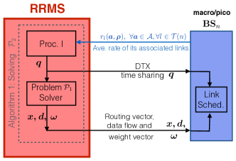
Algorithm 1 shows the pseudo-code of the proposed solution. The indices and are for subframes and superframes, respectively. For updating the short-term control variables at each subframe of the superframe, each BS randomly selects a DTX pattern from the DTX patterns profile based on the DTX time-sharing vector of the current superframe. Then the link scheduling is chosen to maximize the weighted rate as in (7). It should be noted that the DTX patterns generated at different BSs are the same, as explained before.
For updating the long-term control variables at the end of each superframe , first, all BSs feed back the average rate of their outgoing links to the RRMS. Then, the RRMS updates the DTX time sharing vector by Procedure I in section V-B1. Finally, for the updated DTX control and link scheduling policy, the routing and flow control variables and the weight vector (Lagrangian multipliers of ) are updated by solving Problem using the primal-dual method. Note that as earlier mentioned in Remark 2, the weight vector is actually the gradient of the objective function at point .
| (12) |
V-B1 Procedure I (Update of time-sharing vector )
This procedure obtains the updated time-sharing vector by solving the following problem:
| (13) |
where is the link scheduling policy in the superframe as determined by (7), and , where is given in (III). It is easily verified that problem (13) is a convex optimization problem. Therefore, it can be easily solved by the RRMS using the existing convex optimization methods (e.g., primal-dual interior point methods) [33].
Remark 3.
Procedure I requires the conditional average rates as the input, which can be calculated at the RRMS if the distribution of small-scale fading is known. When the distribution of the small-scale fading is not available, the conditional average rates can be calculated at each BS using the running sample average over the subframes of the superframe and then fed back to the RRMS.
V-B2 Convergence and Optimality of Algorithm 1
The following theorem states that Algorithm 1 converges to the global optimal solution of the original problem . The proof is obtained by showing that this algorithm updates the control variables in such a way that the global optimality condition in Theorem 1 is satisfied. Please refer to Appendix A-D for the details.
VI Implementation Considerations
VI-A Signalling Flow
According to the description of the proposed algorithm in the previous section, the signalling flow between the RRMS, macro/pico BSs and MUs within each superframe or each subframe can be illustrated as follows.
Fig. 6 shows the slow-timescale signalling flows that are being passed between the RRMS and each BS at the end of each superframe :
-
1.
Each calculates the average rates of its outgoing links, , and reports them to the RRMS.
-
2.
After updating the long-term control variables based on these average rates, the RRMS sends the updated long-term control variables , and the weights for all outgoing links of to it for the next superframe.
Remark 4.
To provide robustness to the backhaul latency in practical implementations, we allow subframes before the end of each superframe to start to do all of the above long-timescale signalling and calculations. The parameter is chosen as a sufficient time for calculation and message passing. Moreover, since subframes is a small portion of a superframe, it is much less than the coherence time of the channels statistics that are considered to be constant over a long time (i.e., over a large number of superframes). Accordingly, the delay imposed will have no effect on the accuracy of the algorithm.
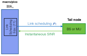
Fig. 7 shows the fast-timescale message passing between the head and tail of each link at each subframe. Note that as we have considered downlink transmission, the head node is always a BS, while the tail node can be either an MU or another BS. At each subframe, each tail node needs to feed back its received SINR over each subband to its transmitting BS so that the transmitting BS can update the short-term link scheduling of its corresponding links accordingly.
From the above analysis, the proposed hierarchical RRM has several advantages in terms of signalling overhead. First, the RRMS requires only global statistical information, which can be provided and fed back by the BSs in long-timescale signalling. This makes the proposed solution robust to the backhaul latency. On the other hand, in the short timescale, BSs only require the local CSI of their outgoing direct links, which can be provided by local message passing between each BS and its associated MUs. As a result, the proposed hierarchical algorithm benefits from low signalling overhead and message passing among different nodes and good scalability of the complexity. In the next subsection, we provide rigorous analysis of the computational complexity and signalling overhead per iteration of the proposed algorithm.
VI-B Signalling Overhead and Computational Complexity
In this section, we elaborate the signalling overhead (in terms of the number of bits exchanged among nodes) and the complexity of the proposed algorithm for each step in each iteration (superframe). For simplicity, we assume that each real number is quantized by bits.
-
1.
Step 1 (link scheduling at each subframe):
Signalling Overhead: For each link , the received SINR over each subband of the tail node should be reported to the head BS. Therefore, the total number of feedback bits per subframe is , and hence, the total signalling overhead per iteration (i.e., superframe) will be bits.
-
2.
Step 2a (DTX time-sharing update):
Signalling Overhead: In this step, the average rate of each link under each DTX pattern is fed back by the associated head BS of the link to the RRMS. Moreover, the RRMS sends the updated DTX time-sharing vector to the BSs. Therefore, the required signalling overhead is bits per iteration.
Computational Complexity: Procedure I that updates DTX time-sharing control includes solving a convex optimization problem as in (13) with the number of variables equal to . Therefore, using primal-dual interior point methods (that are well known to be very efficient for solving convex problems), this problem can be solved in [35], [33, Chapter 11].
-
3.
Step 2b (routing, flow control and the weights update):
Signalling Overhead: The RRMS needs to send the updated long-term variables and to the BSs. Therefore, the signalling overhead of this step is bits per iteration.
To conclude the above discussion, it can be seen that the per-iteration complexity of the overall proposed algorithm is , which is at most polynomial in terms of the key system parameters, such as the number of links, data flows (active users), subbands and DTX patterns. This indicates that the proposed algorithm scales very well with the size of the problem. Moreover the signalling overhead of the proposed scheme is much lower than the signalling overhead of the fast-timescale RRM baseline (which has the signalling overhead of bits per superframe).
VII Simulation Results
In this section, we consider a multi-cell HetNet, as shown in Fig. 8, where each macro cell consists of a macro BS at the center, and four and eight uniformly distributed pico BSs and MUs, respectively. The existence of a line between two nodes in this graph shows that those nodes are in each other’s coverage area, i.e., they can communicate/interfere with each other. The typical values of dBm and dBm have been considered for the transmit power of each macro BS and pico BS, respectively [2]. We consider subframes within each superframe, and assume there are ten available subbands in the network. The PFS utility is considered as the network utility function [30].
For the BS-BS links and BS-MU links, the path loss models of [36, Senario b5a] and [36, Senario c2] (which are compatible with the LTE standard [37]) are considered, respectively. The backhaul delay for global CSI exchange and local CSI exchange are considered to be and , respectively. All the simulation results have been obtained by MATLAB R2014a on a simulation platform with a Windows 7 x64, 2.6-GHz CPU and 8 GB RAM.
We compare the performance of the proposed RRM scheme with the following baselines using numerical simulations. Note that all the baselines are considered with flexible backhaul deployment. Moreover, the first three baselines are two-timescale designs, while the last two baselines are single-timescale designs and are included to show the effectiveness of the proposed two-timescale approach over the conventional fast-timescale or slow-timescale RRM approaches.
-
•
Baseline 1, Alternating Optimisation Approach [38]: The RRMS alternately updates each of the control variables by optimising the objective function with respect to that variable, while considering all the other variables to be fixed. This baseline is included in the simulations in order to show the importance of our considered joint optimization of the control variables and its advantage over alternating optimization.
-
•
Baseline 2, Fixed Routing with Dynamic DTX and Link Scheduling Controls: In this scheme, we consider fixed routing where each MU selects the nearest BS for its last hop communication link. The other control variables are updated in the same way as in our proposed algorithm.
-
•
Baseline 3, Fixed DTX Control with Dynamic Routing, Flow Control and Link Scheduling: Under this scheme, the DTX patterns are selected for each subband with equal probabilities (i.e., ) at each superframe, and the other control variables are determined based on our proposed algorithm. This baseline is included in our comparison in order to show the effectiveness of our proposed DTX time-sharing control scheme.
-
•
Baseline 4, Fast-Timescale RRM Adaptive to the Global Instantaneous CSI: In this baseline, all the RRM control variables (either the long-term or short-term controls) are updated at each subframes, based on the global instantaneous CSI.
-
•
Baseline 5, Slow-Timescale RRM Adaptive to the Statistical CSI: In this baseline, all the RRM control variables are updated at a the slower timescale, i.e., at each superframe, based on the global long-term channel statistics.
VII-A Performance Evaluation and Comparison
Fig. 10 shows the utility function value versus the transmit power of the pico BSs for the proposed algorithm and the aforementioned baselines, when of the BSs are connected to the backhaul. It can be seen from Fig. 10 that the proposed scheme outperforms all the other baselines, due to various advantages of the proposed design over the considered baselines. For example, as shown by our theoretical analysis, the proposed algorithm achieves the optimal solution, while the alternating optimization (AO) algorithm (Baseline 1) does not converge to the optimal solution (as the problem is non-convex, the AO method cannot guarantee global optimality) and hence, it cannot achieve the same performance as ours. Moreover, the proposed two-timescale RRM design outperforms the fast-timescale design (Baseline 4), because, due to the considered two-timescale design, the long-term controls, which require global coordination and signalling, are updated at the slow timescale, and hence the proposed design is less sensitive to the backhaul signalling delay. On the other hand, since the proposed two-timescale approach can exploit multi-user diversity gain by updating the local short-term controls (i.e., link scheduling) in the fast timescale, it also outperforms the slow-timescale design (i.e., Baseline 5). Furthermore, since we also perform dynamic routing in our design, the proposed RRM solution achieves higher performance than Baseline 2, which has fixed routing. In addition, the performance of Baseline 3 shows that if the DTX time-sharing control is not optimised, the performance of the RRM algorithm will be highly degraded compared to our proposed RRM design that optimises the time-sharing of different DTX patterns. Finally, Baseline 5 has the worst performance, since it does not exploit the instantaneous CSI that is locally available at each node to achieve multi-user diversity gain.
Next, Fig. 10 compares the performance of the proposed RRM solution to the baselines, under different portions of BSs connected to the backhaul ranging from to (i.e., the conventional case with full backhaul connection). As expected, when the percentage of the BSs with backhaul connection varies from to , the performance of all the baselines is increasing. Specifically in our proposed scheme, the performance first increases quickly (almost linearly) with the portion of BSs with backhaul connection, and then increases more slowly for larger portions.
VII-B The Average Computational Time and Signalling Overhead
Fig. 12 shows the computational complexity of the proposed algorithm and the baselines in terms of the average CPU time per subframe (for a fair comparison) for different network sizes. We have considered that of the BSs are connected to the backhaul and the pico BS power is . As can be seen from this figure, the computational time (the average CPU time per subframe) of the proposed method grows polynomially with the network size, which is consistent with our analytical results in Section VI-B. Moreover, the computational time of Baseline 4 (fast-timescale RRM) is the highest among all the baselines. This is because this baseline needs to update all the control variables at each subframe. Furthermore, Baseline 1 (the AO approach) also has high computational time, as it needs to optimise each control variable alternatively with other variables fixed, and hence, for updating each control variable at each time, it needs to run an iterative algorithm to solve the optimization problem with respect to the corresponding variable, which takes more time. Finally, the figure shows that the average computational time of the proposed scheme is similar to the other baselines (Baselines 2, 3 and 5) (while the proposed scheme achieves higher performance than them). Specifically, the proposed two-timescale scheme has similar computational time as the slow-timescale RRM scheme (Baseline 5), which is known for having low computational complexity.
Furthermore, Fig. 12 shows the computational complexity of our proposed scheme and the baselines in terms of the average CPU time per subframe, under different portions of the BSs connected to the backhaul, when the pico BS power on each subband is . It can be verified from this figure that under our proposed scheme or any of the baselines, the average CPU time per subframe is similar for different portions of the BSs with backhaul connection. Moreover, it can be seen that the average computational time of our proposed scheme is similar to Baselines 2, 3 and 5. This shows that while the performance of our proposed RRM scheme for flexible backhaul is better than these baselines, its computational complexity is still similar to those baselines with low computational complexity. Furthermore, the average computational time of Baseline 2 per subframe is the smallest, since this baseline does not update the routing controls. However, as shown earlier, the this baseline worse than our proposed method, as it does not utilise dynamic routing. Finally, expected, Baselines 1 and 4 have the highest computational times.
Table II shows the signalling overhead of the proposed scheme and the baselines per BS per subband at each subframe when of the BSs are connected to the backhaul. The signalling overhead is calculated based on the average number of bits that needs to be fed back to/from each BS per one subframe. We have considered bits as the average number of bits used to quantify the each real signalling. As can be seen from this table, the signalling overhead of the proposed two-timescale design is similar to the simple slow timescale design and is much smaller than the fast timescale design. This is mainly due to the proposed two-timescale structure for updating the RRM control variables, in which, the global control variables are updated in a less frequent manner (once per each superframe) than the local control variables. Therefore, while the performance of the proposed scheme highly outperforms the slow timescale RRM scheme (as previously seen in Fig.s 10 and 10), its signalling overhead is similar to the slow timescale RRM design which is well-known for having low signalling overhead. Moreover, the signalling overhead of Baseline 4 (the short-timescale RRM scheme) is significantly higher than the other schemes, since in this baseline, the iterations are done at the short-timescale (i.e., per each subframe), and hence, the required signalling and message passing need to be done significantly more frequently (at each subframe). Furthermore, Baseline 2 (RRM with fixed routing) has the lowest signalling overhead, which is due to the fact that this baseline does not need to update or report the routing variables (Note that its performance is worse than the proposed scheme). Finally, the signalling overhead of Baseline 1 is less than the proposed scheme. However, as seen in the previous figures, its performance as well as computational complexity are worse than the proposed scheme.
| Baselines | Proposed Scheme | Baseline 1 | Baseline 2 | Baseline 3 | Baseline 4 | Baseline 5 |
|---|---|---|---|---|---|---|
| Signalling Overhead (bits) | 43.92 | 21.72 | 11.22 | 44.52 | 17110.92 | 34.81 |
VII-C Trade-off between Cost Saving and Performance Loss under Flexible Backhaul
Fig. 14 shows the trade-off between cost saving and performance loss by reducing the backhaul connections in the network with flexible backhaul. We have assumed 1 unit cost as the average cost of connecting each BS to the backhaul, and have changed the portion of BSs with backhaul connection from to . For each backhaul connection portion, the backhaul cost saving is calculated as the difference between the cost of the backhaul connections for the portion of the BSs connected to the backhaul and the cost of full backhaul connection case, normalised to the cost of full backhaul connection case (which is the maximum cost). As can be seen from this figure, by reducing the backhaul connections, the performance is reduced (as always expected), but at the same time a significant cost in deploying the network will be saved, which can be huge in the emerging densely deployed HetNets with a large number of pico BSs. As a result the considered flexible backhaul can help to save significant share of infrastructure costs for future HetNets.
VII-D Convergence of the Proposed Algorithm
Finally, Fig. 14 shows the convergence result of the proposed scheme and baselines, when pico BS power is . As can be seen in this figure, our proposed scheme achieves the best network utility among all the baselines, with a significant gap compared to them. In fact, the proposed algorithm accomplishes the optimal RRM solution (as previously shown by the analytical proofs), but the other baselines fail to reach the optimal solution and converge to solutions with pretty low network utility values. Moreover, although Baseline 1 (AO approach) achieves a higher network utility than the other baselines, it is still sub-optimal and and the convergence speed of this baseline is very slow, compared to our proposed algorithm that converges to the optimal value very fast (as can be easily seen in this figure). Compared to the other baselines, the proposed algorithm has similar convergence speed, but much higher utility.
VIII Conclusion
In this paper, we considered the problem of RRM for HetNets with flexible backhaul. We formulated the problem with a two-timescale stochastic optimization problem and considered the cross-layer design of flow control, routing control, interference control and link scheduling. Deriving a sufficient condition for the global optimality of a solution, we then proposed an iterative algorithm to reach the global optimal solution. The proposed two-timescale hierarchical design combines the benefits of both fast timescale RRM design and slow timescale RRM design and provides a significant performance gain while low signalling overhead and complexity and robustness to the backhaul latency. Simulation results show that the proposed RRM design achieves significant performance gains over various baselines.
Appendix A
A-A Proof of Lemma 2
If is the global optimal solution of , then from the definition of problems and it follows that would be the optimal solution of . On the other hand, suppose that is the optimal solution to , and satisfies . If is not the global optimal solution of , then there exists another such that . As a consequence, would not be the optimal solution of problem , which is a contradiction.
A-B Proof of Proposition 1
To prove the concavity of the objective function , using the concept of epigraph for convex functions [33], it is sufficient to show that the following set is convex:
| (15) |
Lemma 3.
The set is a convex set.
Proof.
First note that at any arbitrary , the Lagrangian multipliers vector is the gradient of function [32, Proposition 3.3.3] at point . Hence, the -dimensional vector defines a non-vertical supporting hyperplane to at any point [33], i.e.,
| (16) |
We prove Lemma 3 by contradiction: Let’s assume that is NOT a convex set. This implies that there exists some and some , such that
| (17) |
According to the definition of , and belong to the set , and since it is a convex set, as well. This, along with (17), implies that
| (18) |
Now consider point . The supporting hyperplane of at this point, so called , would be as follows:
| (19) | ||||
Substituting into (16), along with (18) and (19), concludes that and any are not located at the same side of the aforementioned hyperplane. In other words, we have
| (20) |
Substituting into (20) and noting that , the following two inequalities are concluded
| (21) | ||||
| (22) |
Multiplying (21) and (22) by and , respectively, and then summing them up together, it is obtained that . However, according to (17), the right-hand side of the above expression equals to . This is obviously a contradiction, and therefore Lemma 3 is proven.
Next, as in the second part of Proposition 1, we prove that the feasible set of is convex, too.
Lemma 4.
is a convex set.
Proof.
In order to prove the convexity of , we show that is the convex hull of the following set, i.e., , where . Note that obviously, . Hence, it is sufficient to show that . According to the definition of in (9), if any point lies in , then every point , where , lies in this region as well. Therefore, in order to prove , it is sufficient to show that any Pareto boundary point of lies in .
As is an -dimensional Pareto boundary point, it can be expressed as a convex combination of points in , i.e., , where , , and . Furthermore, as is a Pareto boundary point of , it follows that the point lies in the supporting hyperplane of at the Pareto boundary point . This fact implies that we can express as a convex combination of points in the set . Hence, , where , , and . Consequently, lies in , which completes the proof of Lemma 4. ∎
A-C Proof of Theorem 1
For proving the sufficient global optimality condition in Theorem 1, we first state the first order optimality condition of problem by Lemma 5. Next, using this lemma, we derive the sufficient global optimality condition for problem , as stated in Theorem 1.
Lemma 5.
(First Order Optimality Condition of Problem ) The vector is the optimal solution for problem if
| (23) |
where is the gradient of at point .
Proof.
Suppose satisfies (23), and define a function over the domain . From the concavity of function , it follows that . Moreover, from (23), it is easy to see that . Therefore, combining the aforementioned two inequalities results that . Hence, is the global optimal solution for problem .
Now suppose satisfies condition (11) in Theorem 1. It easily follows from (11) along with the definition of in (9) that
| (24) |
Using Lemma 5, the above inequality results that satisfies the first-order global optimality condition for , and hence, it is the global optimal solution to problem . Consequently, according to Lemma 2, it is the optimal solution to problem as well.
A-D Proof of Theorem 2
Assume that is the DTX time-sharing and link scheduling control policy obtained in the iteration of Algorithm 1. According to (7) and (13), clearly , which implies that Algorithm 1 is increasing. This, along with the fact that the objective value is upper bounded, concludes that the algorithm is convergent, i.e., , where is the convergence value of Algorithm 1.
Now, let be any limiting point of the sequence generated by the algorithm and define and as the optimal solution of the following optimization problem:
| (25) |
where is determined by (7). Obviously, we have
Moreover, according to (7), is maximising with respect to over the domain . Therefore, it is concluded that
| (26) |
where the second inequality is due to the definition of and the last one is due to the fact that . Combining (A-D) and the concavity of results in
| (27) |
where is the global optimal solution of problem and is the optimal value. Consequently, it follows that
| (28) |
where the last inequality follows from the fact that is the optimal (i.e., maximum) value of .
To prove that the convergence value of Algorithm 1 equals to the global optimal solution of the problem, i.e., , it suffices to show that the left hand side of (A-D) is less than or equal to 0. In the following, we will prove it by contradiction: Assume that , for some . Hence, using Taylor expansion at point , we have
| (29) |
for some sufficiently small . Consequently, for a sufficiently small value of , we have Therefore, we have found some point with a strictly larger utility value than the utility value at point . Note that this point is in fact , where
Hence, , which contradicts with the fact that is the maximiser of with respect to (according to (13)). Therefore, the left hand side of (A-D) is equal to 0 and hence, , which indicates that the proposed algorithm converges to the optimal solution of . Moreover, assume that is the solution to subproblem under , derived from Step 2b of Algorithm 1. According to Lemma 1, we have that is the optimal solution to the original problem . Therefore, we have , which completes the proof.
References
- [1] N. Omidvar, A. Liu, V. Lau, F. Zhang, D. Tsang, and M. R. Pakravan, “Two-timescale radio resource management for heterogeneous networks with flexible backhaul,” in 2015 IEEE Global Communications Conference (GLOBECOM). IEEE, 2015, pp. 1–6.
- [2] A. Damnjanovic, J. Montojo, Y. Wei, T. Ji, T. Luo, M. Vajapeyam, T. Yoo, O. Song, and D. Malladi, “A survey on 3GPP heterogeneous networks,” Wireless Communications, IEEE, vol. 18, no. 3, pp. 10–21, 2011.
- [3] M. Paolini, “Crucial economics for mobile data backhaul,” White paper, 2011.
- [4] S. Tombaz, P. Monti, K. Wang, A. Vastberg, M. Forzati, and J. Zander, “Impact of backhauling power consumption on the deployment of heterogeneous mobile networks,” in Global Telecommunications Conference (GLOBECOM 2011). IEEE, 2011, pp. 1–5.
- [5] F. Farias, P. Monti, A. Vastberg, M. Nilson, J. Costa, and L. Wosinska, “Green backhauling for heterogeneous mobile access networks: What are the challenges?” in 9th International Conference on Information, Communications and Signal Processing (ICICS). IEEE, 2013, pp. 1–5.
- [6] M. Tornatore, G.-K. Chang, and G. Ellinas, Fiber-Wireless Convergence in Next-Generation Communication Networks: Systems, Architectures, and Management. Springer, 2017.
- [7] H. Wu, C. Qiao, S. De, and O. Tonguz, “Integrated cellular and ad hoc relaying systems: iCAR,” Selected Areas in Communications, IEEE Journal on, vol. 19, no. 10, pp. 2105–2115, 2001.
- [8] V. Sreng, H. Yanikomeroglu, and D. D. Falconer, “Relayer selection strategies in cellular networks with peer-to-peer relaying,” in 58th Vehicular Technology Conference, vol. 3. IEEE, 2003, pp. 1949–1953.
- [9] Ö. Bulakci, A. B. Saleh, S. Redana, B. Raaf, and J. Hämäläinen, “Flexible backhaul resource sharing and uplink power control optimization in LTE-advanced relay networks,” in Vehicular Technology Conference (VTC Fall). IEEE, 2011, pp. 1–6.
- [10] R. Pabst, B. H. Walke, D. C. Schultz, P. Herhold, H. Yanikomeroglu, S. Mukherjee, H. Viswanathan, M. Lott, W. Zirwas, M. Dohler et al., “Relay-based deployment concepts for wireless and mobile broadband radio,” Communications Magazine, IEEE, vol. 42, no. 9, pp. 80–89, 2004.
- [11] D. Niyato, E. Hossain, D. I. Kim, and Z. Han, “Relay-centric radio resource management and network planning in IEEE 802.16 j mobile multihop relay networks,” IEEE Transactions on wireless communications, vol. 8, no. 12, 2009.
- [12] Y. Wang and K. I. Pedersen, “Performance analysis of enhanced inter-cell interference coordination in LTE-advanced heterogeneous networks,” in 75th Vehicular Technology Conference (VTC Spring). IEEE, 2012, pp. 1–5.
- [13] J. Pang, J. Wang, D. Wang, G. Shen, Q. Jiang, and J. Liu, “Optimized time-domain resource partitioning for enhanced inter-cell interference coordination in heterogeneous networks,” in Wireless Communications and Networking Conference (WCNC). IEEE, 2012, pp. 1613–1617.
- [14] A. Liu, V. K. Lau, L. Ruan, J. Chen, and D. Xiao, “Hierarchical radio resource optimization for heterogeneous networks with enhanced inter-cell interference coordination (eICIC),” Signal Processing, IEEE Transactions on, vol. 62, no. 7, pp. 1684–1693, 2014.
- [15] N. Omidvar, F. Zhang, A. Liu, V. K. Lau, D. H. Tsang, and M. R. Pakravan, “Cross-layer QSI-aware radio resource management for HetNets with flexible backhaul,” in Wireless Communications and Networking Conference (WCNC 2016), Doha, Qatar. IEEE, 2016, pp. 945–950.
- [16] N. Omidvar, A. Liu, V. Lau, F. Zhang, D. H. Tsang, and M. R. Pakravan, “Two-timescale QoS-aware cross-layer optimisation for HetNets with flexible backhaul,” in Personal, Indoor, and Mobile Radio Communications (PIMRC), 2015 IEEE 26th Annual International Symposium on. IEEE, 2015, pp. 1072–1076.
- [17] N. Khaled, B. Mondal, G. Leus, R. W. Heath, and F. Petré, “Interpolation-based multi-mode precoding for MIMO-OFDM systems with limited feedback,” IEEE Transactions on Wireless Communications, vol. 6, no. 3, 2007.
- [18] A. K. Sadek, W. Su, and K. R. Liu, “Transmit beamforming for space-frequency coded MIMO-OFDM systems with spatial correlation feedback,” IEEE Transactions on Communications, vol. 56, no. 10, pp. 1647–1655, 2008.
- [19] M. Z. Hasan, H. Al-Rizzo, and F. Al-Turjman, “A survey on multipath routing protocols for QoS assurances in real-time wireless multimedia sensor networks,” IEEE Communications Surveys & Tutorials, 2017.
- [20] A. Khandekar, N. Bhushan, J. Tingfang, and V. Vanghi, “LTE-advanced: Heterogeneous networks,” in European Wireless Conference (EW). IEEE, 2010, pp. 978–982.
- [21] J. He and J. Rexford, “Toward internet-wide multipath routing,” IEEE network, vol. 22, no. 2, 2008.
- [22] S. Kandula, D. Katabi, S. Sinha, and A. Berger, “Dynamic load balancing without packet reordering,” ACM SIGCOMM Computer Communication Review, vol. 37, no. 2, pp. 51–62, 2007.
- [23] W. Xu and J. Rexford, MIRO: multi-path interdomain routing. ACM, 2006, vol. 36, no. 4.
- [24] S. K. Singh, T. Das, and A. Jukan, “A survey on internet multipath routing and provisioning,” IEEE Communications Surveys & Tutorials, vol. 17, no. 4, pp. 2157–2175, 2015.
- [25] I. Gasparis, U. C. Kozat, and M. O. Sunay, “Programming flows in dense mobile environments: A multi-user diversity perspective,” arXiv preprint arXiv:1506.07816, 2015.
- [26] D. Astély, E. Dahlman, A. Furuskär, Y. Jading, M. Lindström, and S. Parkvall, “LTE: the evolution of mobile broadband,” IEEE Communications magazine, vol. 47, no. 4, 2009.
- [27] S. Deb, P. Monogioudis, J. Miernik, and J. P. Seymour, “Algorithms for enhanced inter-cell interference coordination (eICIC) in LTE HetNets,” IEEE/ACM transactions on networking, vol. 22, no. 1, pp. 137–150, 2014.
- [28] A. Liu, V. K. N. Lau, L. Ruan, J. Chen, and D. Xiao, “Hierarchical radio resource optimization for heterogeneous networks with enhanced inter-cell interference coordination (eICIC),” CoRR, vol. abs/1305.5884, 2013. [Online]. Available: http://arxiv.org/abs/1305.5884.
- [29] J. Mo and J. Walrand, “Fair end-to-end window-based congestion control,” IEEE/ACM Transactions on Networking (ToN), vol. 8, no. 5, pp. 556–567, 2000.
- [30] F. P. Kelly, A. K. Maulloo, and D. K. Tan, “Rate control for communication networks: Shadow prices, proportional fairness and stability,” Journal of the Operational Research Society, pp. 237–252, 1998.
- [31] D. P. Palomar and M. Chiang, “A tutorial on decomposition methods for network utility maximization,” IEEE Journal on Selected Areas in Communications, vol. 24, no. 8, pp. 1439–1451, 2006.
- [32] D. P. Bertsekas, Nonlinear Programming. Athena Scientific, 1999.
- [33] S. Boyd and L. Vandenberghe, Convex Optimization. Cambridge University Press, 2009.
- [34] S. E. Anderson, “Bit twiddling hacks,” URL: http://graphics.stanford.edu/~seander/bithacks. html, 2005.
- [35] S. S. Skiena, The algorithm design manual. Springer Science & Business Media, 2008.
- [36] I. IST-WINNER, “Deliverable 1.1.2 v.1.2, “WINNER II channel models”, IST-WINNER2,” Tech. Rep., 2008 (http://projects.celti c-initiative.org/winner+/deliverables.html), Tech. Rep., 2007.
- [37] M. Hossain, R. Adhikary, and N. Yesmin, “Performance evaluation of WINNER-II channel model for long term evolution (LTE),” International Journal of Scientific & Engineering Research, vol. 4, no. 5, 2013.
- [38] J. C. Bezdek and R. J. Hathaway, “Convergence of alternating optimization,” Neural, Parallel & Scientific Computations, vol. 11, no. 4, pp. 351–368, 2003.