Chiral structures and defects of lyotropic chromonic liquid crystals induced by saddle-splay elasticity
Abstract
An experimental and theoretical study of lyotropic chromonic liquid crystals (LCLCs) confined in cylinders with degenerate planar boundary conditions elucidates LCLC director configurations. When the Frank saddle-splay modulus is more than twice the twist modulus, the ground state adopts an inhomogeneous escaped-twisted configuration. Analysis of the configuration yields a large saddle-splay modulus, which violates Ericksen inequalities but not thermodynamic stability. Lastly, we observe point defects between opposite-handed domains and explain a preference for point defects over domain walls.
pacs:
61.30.Jf, 61.30.Pq, 62.20.de, 68.37.-dThe elastic properties of nematic liquid crystals (LCs) are crucial for liquid crystal display applications Schadt and Helfrich (1971); Yeh and Gu (2010), and they continue to give rise to unanticipated fundamental phenomena Jeong et al. (2014, 2015); Škarabot et al. (2008); Rao et al. (2009); Gibaud et al. (2012); Jones (2012); Li (2012). Three of the bulk nematic LC deformation modes, splay, twist and bend, are well known and have associated elastic moduli , and , respectively. These moduli have been intensely studied because they are easy to visualize, and because it is possible to independently excite the modes via clever usage of sample geometry Hakemi et al. (1983); Giavazzi et al. (2014); Zhou et al. (2014), LC boundary conditions Sparavigna et al. (1994); Lavrentovich (1992), and external fields Fréedericksz and Zolina (1933); Zhou et al. (2012). As a result, these moduli have been measured for a variety of thermotropic and lyotropic LCs Karat and Madhusudana (1976, 1977); Madhusudana and Pratibha (1982); Bogi and Faetti (2001); Zhou et al. (2012, 2014). By contrast, a much less studied fourth independent mode Nehring and Saupe (1971); Crawford and Žumer (1995); Schmidt (1990) of elastic deformation in nematic LCs can exist; it is called saddle-splay. Saddle-splay is hard to visualize and to independently excite Schmidt (1990); Palffy-Muhoray (1990). Moreover, the energy of this deformation class can be integrated to the boundary, so that the mode does not appear in the Euler-Lagrange equations, and with fixed boundary conditions, the saddle-splay energy will have no effect on the LC director configuration. Even with free boundary conditions, the saddle-splay energy will not affect the bulk LC configuration unless the principal curvatures of the surface are different, i.e., saddle-splay effects are not expected for spherical or flat surfaces. Thus, although much progress in understanding saddle-splay has been made de Gennes and Prost (1995); Alexander et al. (2012), especially with thermotropic nematic LCs, unambiguous determination of saddle-splay energy effects on liquid crystal configurations and measurement of the saddle-splay elastic modulus, , remain difficult Joshi et al. (2014).
While the bulk elastic constants described above strongly influence LC director configurations, LC boundary conditions at material interfaces also influence bulk structure. Indeed, considerable effort has gone into development of surface preparation techniques to produce particular bulk director configurations Schadt et al. (1992); Nazarenko et al. (2010); Zimmermann et al. (2015); Lee and Clark (2001); Willman et al. (2014); Sparavigna et al. (1994); McGinn et al. (2013). The saddle-splay term integrates to the boundary and effectively imposes boundary conditions at free surfaces favoring director alignment along the direction of highest surface curvature for positive Koning et al. (2014) and outwardly pointing surface normals. For this effect to be present, the director cannot be held perpendicular to the surface, as was the case in our prior work Jeong et al. (2015). The potential role of saddle-splay effects in determining bulk director configurations by spontaneous symmetry breaking has been appreciated Pairam et al. (2013); Crawford et al. (1992); Hough et al. (2009); Sparavigna et al. (1994) but has been difficult to fully characterize; generally, molecular surface forces can impose preferred boundary conditions that are hard to disentangle from effects due to Ondris-Crawford et al. (1993); Melzer and Nabarro (1977). As a result, the measurements of to date have wide confidence intervals Allender et al. (1991); Pairam et al. (2013); Polak et al. (1994) and even vary in sign Polak et al. (1994). Finally, additional factors that have complicated assignment of saddle-splay effects are the so-called Ericksen inequalities Ericksen (1966) that require and . These inequalities were derived assuming spatially uniform gradients of the director. They do not, however, apply in geometries such as ours in which gradients are not uniform.
In this contribution, we investigate director configurations of the nematic lyotropic chromonic liquid crystal (LCLC) Sunset Yellow (SSY) confined within cylindrical glass capillaries with degenerate planar boundary conditions as initially reported by Refs. Davidson et al. (2014, 2015); Chang et al. (2015). Our study employs a combination of polarized optical microscopy, measurements of director-field thermal fluctuations, and Frank-free-energy calculations to rationalize the observed structures. Importantly, we show that a large leads to an escaped-twist (ET) ground state, which exhibits a classic double-twist configuration. Note, chiral symmetry breaking in the ET configuration is fundamentally different from symmetry breaking in other LCLC systems with uniform principal curvatures Jeong et al. (2014), or with homeotropic boundary conditions Jeong et al. (2015). In the previous work, spontaneous twist deformation arises because is much smaller than and ; played no role in the energetics. In the present work, comparison of theory and experiment enables us to measure for the first time in a LCLC; we find a value of , which strongly violates the Ericksen inequalities. Finally, we observe and characterize chiral hegdehog point defects separating chiral domains of opposite handedness. Interestingly, the presence of point defects rather than smooth domain walls also provides precise quantitative information about that is consistent with our other conclusions.
Before discussing the experimental results, we formulate the theoretical problem. We assume the achiral nematic LCLC is described by a Frank free energy, i.e.,
| (1) |
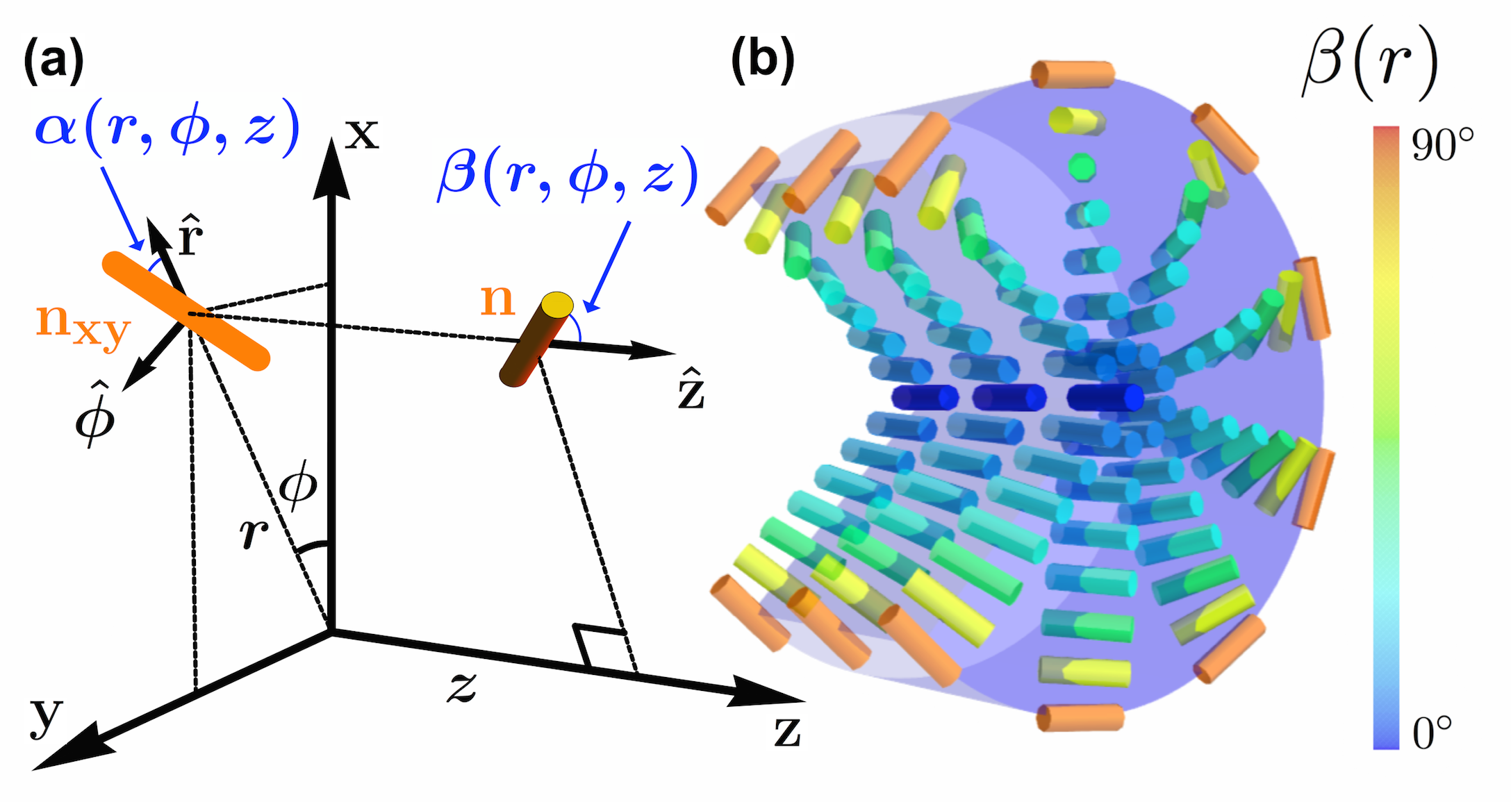
where is the nematic director. Equation (1) explicitly includes the saddle-splay term with modulus , which can in principle be mimicked by a surface anchoring term that is coupled to surface curvature; thus we consider a saddle-splay term that combines the two effects Biscari and Terentjev (2006); Not . A Rapini-Papoular type surface anchoring term with in-plane anisotropy Ondris-Crawford et al. (1993); Crawford and Žumer (1995) is excluded and discussed later in the text. The LC is contained inside a capillary of radius and cylindrical coordinates are used to parameterize its director field, , with along the capillary axis (see Fig. 1), i.e.,
| (2) |
To determine the configuration of the ground state, we assume the director depends only on and minimize the Frank free energy with respect to and . Degenerate planar anchoring conditions at the capillary surface prevent the director from having an -component, so . Cylindrical symmetry sets . Both and are free to vary, but stationarity of the free energy provides the boundary conditions: and .
With these boundary conditions, the Euler-Lagrange equations of the Frank free energy give Ondris-Crawford et al. (1993)
| (3) | |||||
| (4) |
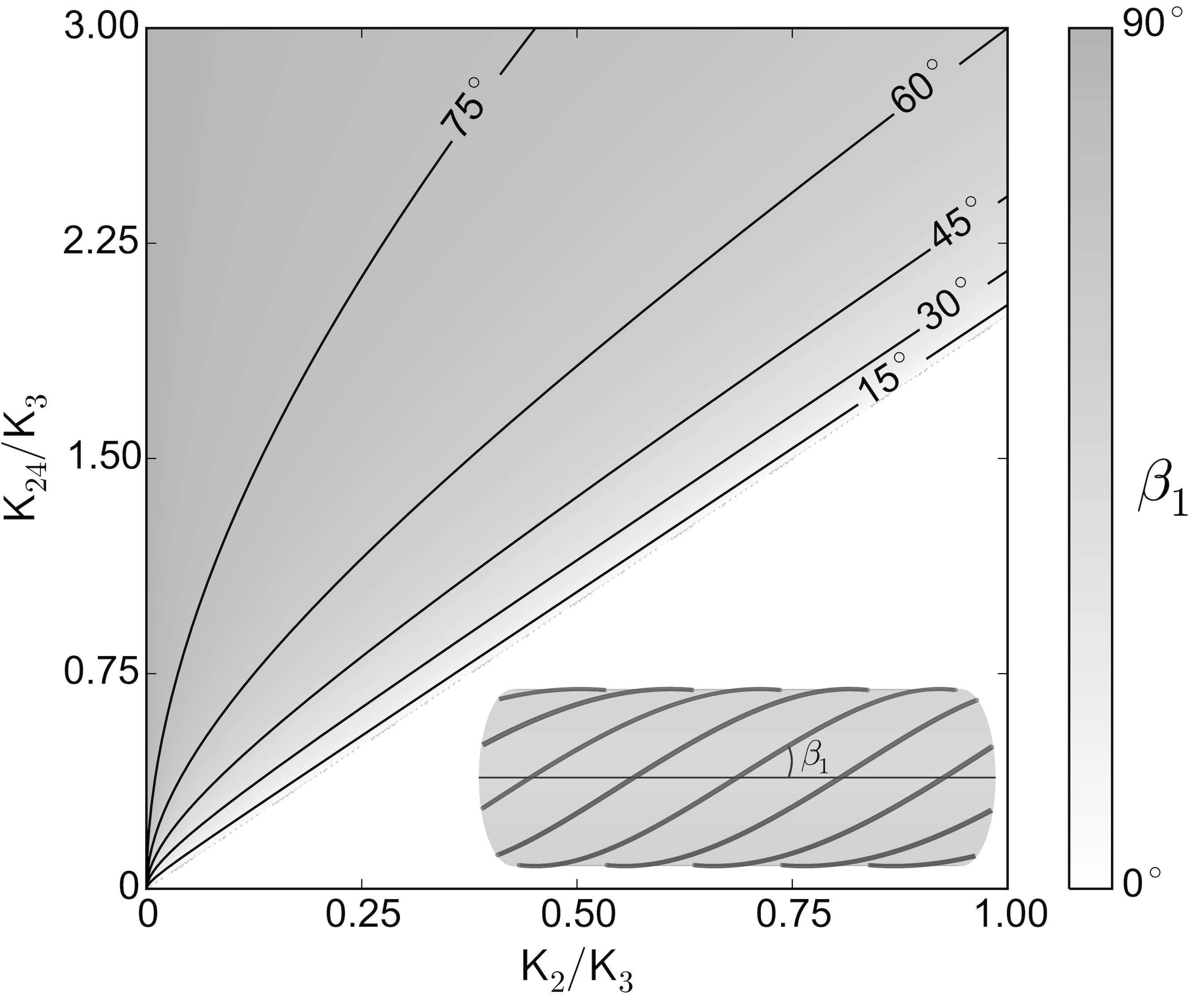
This ET solution exists for and has right-handed chirality, i.e., the director streamlines form right-handed helices. A mirror-image solution exists with the same energy. Notice that the radial position is scaled by the cylinder radius and that does not appear because this configuration has no splay. If , then only the trivial solution exists, which corresponds to the simple parallel-axial configuration Crawford et al. (1992). As surpasses , which is exactly the upper bound found by Ericksen, the system spontaneously breaks chiral symmetry, and an ET configuration of one handedness grows continuously from the trivial solution. is plotted in Fig. 2. Prior work with thermotopic LCs has found this ET configuration when an azimuthal anchoring condition dominates the behavior of at the capillary surface through a chemical or mechanical treatment of the surface Ondris-Crawford et al. (1993); Melzer and Nabarro (1977); Cladis and Kléman (1972). (Eq. 4) can only be approximated by a linear twist model Koning et al. (2014) for certain ratios of elastic constants. For LCs whose elastic moduli do not satisfy these ratios, such as SSY, polarized optical microscopy textures are strongly affected by the nonlinear behavior of Not .
The normalized free energy of the ET configuration is readily calculated to be
where is the length of the capillary. Notice that as increases beyond , the free energy decreases continuously from , thereby confirming that the ET configuration as a ground state is preferred over the uniform configuration whenever it can exist; marks a second-order phase transition line. The key to this energetic stabilization is the saddle-splay term:
| (6) |
As noted by Ref. Koning et al. (2014), who use an opposite surface normal convention, couples the nematic director to the surface curvature tensor and favors alignment in the direction of highest curvature for . In our case, this is the azimuthal direction along the circumference of the capillary. Thus, the saddle-splay free energy stabilizes the ET configuration despite introducing bulk director distortion. We also have verified that both the ET and the deformation-free solutions are stable whenever they are preferred ( and , respectively); that is, their stability matrices have positive eigenvalues (see Supplemental Information) Not .
Our experimental investigations used nematic SSY, a LCLC with relatively low twist modulus Zhou et al. (2012). Briefly, five SSY samples were loaded into five different capillary tubes with diameters 100 µm , from VitroCom (CV1017-100). The sealed samples were illuminated between cross-polarizers by 10nm-bandpass-filtered 660 nm LED light at high (160x) magnification, enabling small depth of field and high spatial resolution imaging. Images were captured by a Uniq UP680-CL video camera, and a piezo-objective positioner was moved to image focal planes within the samples in 1 µm intervals.
The capillaries without surface treatment were loaded with SSY and sealed to prevent evaporation. A critical experimental question for any saddle-splay study concerns possible structure on the cylinder interfaces that could induce a preferred anchoring direction. To this end, we examined the inner capillary surfaces using atomic force microscopy (AFM) and scanning electron microscopy (SEM), and we compared the inner capillary surfaces to rubbed glass; the capillaries had no discernible grooved structures as on the rubbed glass. Since SSY is known to exhibit natural planar anchoring on smooth glass surfaces Nazarenko et al. (2010), our observations of the capillary surface strongly suggest that degenerate planar boundary conditions are present on the inner surfaces of the cylinders and any anisotropic Rapini-Papoular type anchoring effect would be small Ondris-Crawford et al. (1993); Crawford and Žumer (1995); Not . We also considered alignment caused by flow during capillary filling. Loading capillaries with the LCLC in either the nematic or the isotropic phase resulted in the same type of director configurations. Further, since the filling flow is nearly perpendicular to the final alignment found at the capillary surface, flow alignment appears unlikely. Finally, we considered the possibility that a layer of molecules adsorbed to the capillary surface sets an easy access at the capillary surface during or shortly after filling. We exclude this possibility by cycling the filled capillary between nematic and isotropic phase and observing that the director at the capillary surface retains no memory from cycle to cycle Not .
We measure the director angle, , directly by observing a flickering speckle pattern and its direction in the LC. The pattern originates from director field temporal fluctuations and accompanying fluctuations in the ordinary and extraordinary refractive indices which cause scattering de Gennes and Prost (1995). These types of fluctuations of the director field have been exploited previously to measure the viscoelastic ratios of liquid crystals Hakemi et al. (1983); Giavazzi et al. (2014); Zhou et al. (2014). Our work follows Ref.Giavazzi et al. (2014), which proposed using videos of LC flickering to discern local orientation of the director field Not . Flickering shape and direction depend on the local director field configuration and LC viscoelastic anisotropy.

The experimentally measured for one of the five LCLC samples studied is shown in Fig. 3c. It is well fit by the calculated expression (Eq. 4), and the fitting provides experimental values for ratios of the twist-to-bend and saddle-splay-to-bend elastic constants. The twist-to-bend ratio is in close agreement with prior measurements Zhou et al. (2012). Since when , the fit values become increasingly sensitive to experimental uncertainties as . For example, the fit value of is sensitive to the uncertainty of the measured size of the capillary radius, Not . For the data in Fig. 3c, the capillary was measured to have a diameter of µm to within µm. This relatively small uncertainty, however, leads to the large uncertainty we give for our estimate of , i.e., has a mean value averaged across experiments of with bounding interval . By contrast, is a stiff parameter in the fit; it has a mean value averaged across experiments of 0.12 and a standard deviation Not .
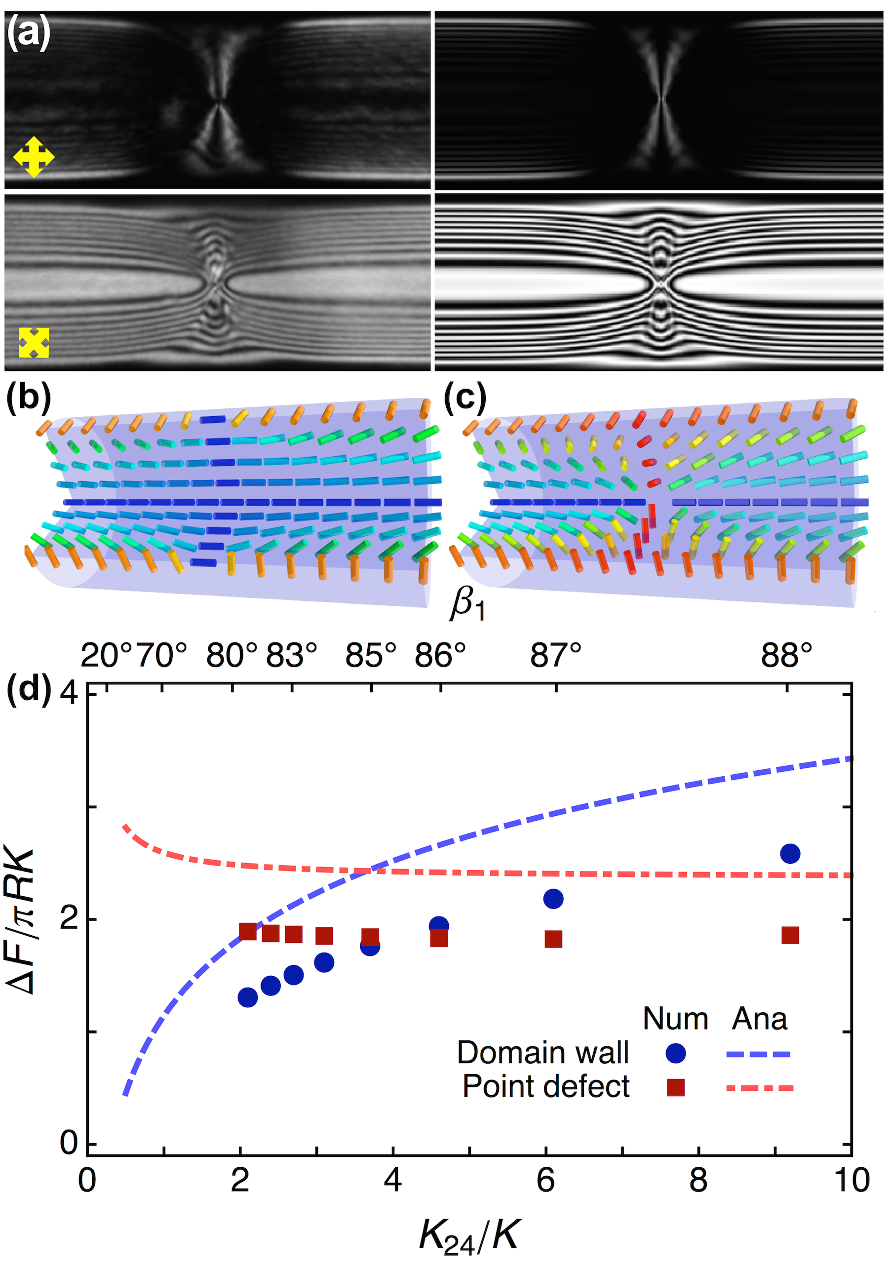
We also observed hedgehog defects associated with the ET configuration. In long capillaries, we typically observed ET domains of opposite handedness separated by chiral point defects. These defects were qualitatively proposed in Ref. Melzer and Nabarro (1977). We observed annihilation of neighboring defects, indicating that they carry opposite topological chargeNot . The presence of nematic director singularities are apparent in Fig. 4a; bright-field microscopy Not reveals dark spots from scattered light along the center of the capillary. Once found, we image the point defect under crossed-polarizers with the same illumination described above. We compare these experimental textures with those simulated numerically using Jones matrices Not . The comparison requires a test director configuration, which we calculate using Eqs. 1 and 2. For configurations in the presence of defects, however, the director depends on both and ; the boundary conditions at bring the director configuration back to ET configurations with opposite handedness. To arrive at an optimized guess, we solve the Euler-Lagrange equations numerically with a relaxational technique Not . The configurations that emerge are very similar to what one gets if one takes the standard radial and hyperbolic hedgehogs and simply rotates all directors by about the -axis Not . This simple operation, which is guaranteed to preserve hedgehog charge, automatically produces opposite chirality on opposite sides along of the hedgehog defect regardless of the sign () of its charge. The topological charges of successive hedgehogs necessarily alternate in sign Not . Using , and , numbers which are consistent with our measurements in the ET ground state, we observed remarkable agreement between experimental and theoretical textures (Fig. 4a).
In principle, smooth domain walls can also separate domains of opposite handedness, in which the escaped-twist configuration continuously untwists from one domain to the wall mid-plane and then continuously re-twists with opposite handedness into the other domain (see Fig. 4b). In this case, throughout the mid-plane, the director would align along the capillary axis. However, in SSY, we have never experimentally observed such a domain wall structure. Defect energetics provide an explanation for this observation which has an interesting consequence. Again, we numerically calculate the configurations of both domain walls and point defects to obtain their energies Not . For these calculations, we fix in accordance with Zhou et al. (2012) and our fluctuation experiments, and we allow to vary. As shown in Fig. 4d, point defects (domain walls) have lower energy than domain walls (point defects) for (). Using from Zhou et al. (2012) and , a typical dimensionless energy difference of corresponds to , where is the experimental temperature. If is greater than the crossover value , then, according to theory, one should not expect to observe smooth domain walls. Thus, both our observations of defects (or lack thereof) and our energy analysis set as an approximate lower bound for , in agreement with our fluctuation-measured value of .
In summary, we have completed an experimental and theoretical study of a lyotropic chromonic liquid crystal, Sunset Yellow, in its nematic phase and confined in a hollow cylinder with degenerate planar boundary conditions. The escaped-twist configurations found to form in the bulk require a large saddle-splay modulus, which we have measured. We also observed point defects in this system whose existence (compared to the absence of smooth domain walls) provides independent confirmation of . In the future, it will be interesting to study and manipulate these chiral configurations and investigate their formation from the isotropic phase.
Acknowledgements.
We thank Randall Kamien for helpful discussions and gratefully acknowledge financial support from National Science Foundation Grants DMR-1205463, DMR-1120901, DMR-1104707 and National Aeronautics and Space Administration Grant #NNX08AO0G.References
- Schadt and Helfrich (1971) M. Schadt and W. Helfrich, Appl. Phys. Lett. 18, 127 (1971).
- Yeh and Gu (2010) P. Yeh and C. Gu, Optics of Liquid Crystal Displays (John Wiley & Sons, 2010).
- Jeong et al. (2014) J. Jeong, Z. S. Davidson, P. J. Collings, T. C. Lubensky, and A. G. Yodh, Proc. Nat. Acad. Sci. 111, 1742 (2014).
- Jeong et al. (2015) J. Jeong, L. Kang, Z. S. Davidson, P. J. Collings, T. C. Lubensky, and A. G. Yodh, Proc. Nat. Acad. Sci. , 201423220 (2015).
- Škarabot et al. (2008) M. Škarabot, M. Ravnik, S. Žumer, U. Tkalec, I. Poberaj, D. Babič, and I. Muševič, Phys. Rev. E 77, 061706 (2008).
- Rao et al. (2009) L. Rao, Z. Ge, S.-T. Wu, and S. H. Lee, Appl. Phys. Lett. 95, 231101 (2009).
- Gibaud et al. (2012) T. Gibaud, E. Barry, M. J. Zakhary, M. Henglin, A. Ward, Y. Yang, C. Berciu, R. Oldenbourg, M. F. Hagan, D. Nicastro, R. B. Meyer, and Z. Dogic, Nature 481, 348 (2012).
- Jones (2012) C. Jones, in Handbook of Visual Display Technology, edited by J. Chen, W. Cranton, and M. Fihn (Springer Berlin Heidelberg, 2012) pp. 1507–1543.
- Li (2012) Q. Li, Liquid Crystals Beyond Displays: Chemistry, Physics, and Applications (John Wiley & Sons, 2012).
- Hakemi et al. (1983) H. Hakemi, E. F. Jagodzinski, and D. B. DuPré, J. Chem. Phys. 78, 1513 (1983).
- Giavazzi et al. (2014) F. Giavazzi, S. Crotti, A. Speciale, F. Serra, G. Zanchetta, V. Trappe, M. Buscaglia, T. Bellini, and R. Cerbino, Soft Matter 10, 3938 (2014).
- Zhou et al. (2014) S. Zhou, K. Neupane, Y. A. Nastishin, A. R. Baldwin, S. V. Shiyanovskii, O. D. Lavrentovich, and S. Sprunt, Soft Matter 10, 6571 (2014).
- Sparavigna et al. (1994) A. Sparavigna, O. D. Lavrentovich, and A. Strigazzi, Phys. Rev. E 49, 1344 (1994).
- Lavrentovich (1992) O. D. Lavrentovich, Phys. Rev. A 46, R722 (1992).
- Fréedericksz and Zolina (1933) V. Fréedericksz and V. Zolina, Trans. Faraday Soc. 29, 919 (1933).
- Zhou et al. (2012) S. Zhou, Y. A. Nastishin, M. M. Omelchenko, L. Tortora, V. G. Nazarenko, O. P. Boiko, T. Ostapenko, T. Hu, C. C. Almasan, S. N. Sprunt, J. T. Gleeson, and O. D. Lavrentovich, Phys. Rev. Lett. 109, 037801 (2012).
- Karat and Madhusudana (1976) P. P. Karat and N. V. Madhusudana, Mol. Cryst. Liq. Cryst. 36, 51 (1976).
- Karat and Madhusudana (1977) P. P. Karat and N. V. Madhusudana, Mol. Cryst. Liq. Cryst. 40, 239 (1977).
- Madhusudana and Pratibha (1982) N. V. Madhusudana and R. Pratibha, Molecular Crystals and Liquid Crystals 89, 249 (1982).
- Bogi and Faetti (2001) A. Bogi and S. Faetti, Liquid Crystals 28, 729 (2001).
- Nehring and Saupe (1971) J. Nehring and A. Saupe, J. Chem. Phys. 54, 337 (1971).
- Crawford and Žumer (1995) G. P. Crawford and S. Žumer, Int. J. Mod. Phys. B 09, 2469 (1995).
- Schmidt (1990) V. H. Schmidt, Phys. Rev. Lett. 64, 535 (1990).
- Palffy-Muhoray (1990) P. Palffy-Muhoray, Phys. Rev. Lett. 65, 1828 (1990).
- de Gennes and Prost (1995) P. G. de Gennes and J. Prost, The Physics of Liquid Crystals (Clarendon Press, 1995).
- Alexander et al. (2012) G. P. Alexander, B. G. Chen, E. A. Matsumoto, and R. D. Kamien, Rev. Mod. Phys. 84, 497 (2012).
- Joshi et al. (2014) A. A. Joshi, J. K. Whitmer, O. Guzm n, N. L. Abbott, and J. J. de Pablo, Soft Matter 10, 882 (2014).
- Schadt et al. (1992) M. Schadt, K. Schmitt, V. Kozinkov, and V. Chigrinov, Jpn. J. Appl. Phys. 31, 2155 (1992).
- Nazarenko et al. (2010) V. G. Nazarenko, O. P. Boiko, H.-S. Park, O. M. Brodyn, M. M. Omelchenko, L. Tortora, Y. A. Nastishin, and O. D. Lavrentovich, Phys. Rev. Lett. 105, 017801 (2010).
- Zimmermann et al. (2015) N. Zimmermann, G. Jünnemann-Held, P. J. Collings, and H.-S. Kitzerow, Soft Matter 11, 1547 (2015).
- Lee and Clark (2001) B. Lee and N. A. Clark, Science 291, 2576 (2001).
- Willman et al. (2014) E. Willman, L. Seddon, M. Osman, A. Bulak, R. James, S. E. Day, and F. A. Fernandez, Phys. Rev. E 89, 052501 (2014).
- McGinn et al. (2013) C. K. McGinn, L. I. Laderman, N. Zimmermann, H.-S. Kitzerow, and P. J. Collings, Phys. Rev. E 88, 062513 (2013).
- Koning et al. (2014) V. Koning, B. C. van Zuiden, R. D. Kamien, and V. Vitelli, Soft Matter 10, 4192 (2014).
- Crawford et al. (1992) G. P. Crawford, D. W. Allender, and J. W. Doane, Phys. Rev. A 45, 8693 (1992).
- Pairam et al. (2013) E. Pairam, J. Vallamkondu, V. Koning, B. C. van Zuiden, P. W. Ellis, M. A. Bates, V. Vitelli, and A. Fernandez-Nieves, Proc. Nat. Acad. Sci. 110, 9295 (2013).
- Hough et al. (2009) L. E. Hough, H. T. Jung, D. Krüerke, M. S. Heberling, M. Nakata, C. D. Jones, D. Chen, D. R. Link, J. Zasadzinski, G. Heppke, J. P. Rabe, W. Stocker, E. Körblova, D. M. Walba, M. A. Glaser, and N. A. Clark, Science 325, 456 (2009).
- Ondris-Crawford et al. (1993) R. J. Ondris-Crawford, G.P. Crawford, S. Žumer, and J. W. Doane, Phys. Rev. Lett. 70, 194 (1993).
- Melzer and Nabarro (1977) D. Melzer and F. R. N. Nabarro, Phil. Mag. 35, 901 (1977).
- Allender et al. (1991) D. W. Allender, G. P. Crawford, and J. W. Doane, Phys. Rev. Let. 67, 1442 (1991).
- Polak et al. (1994) R. D. Polak, G. P. Crawford, B. C. Kostival, J. W. Doane, and S. Žumer, Phys. Rev. E 49, R978 (1994).
- Ericksen (1966) J. L. Ericksen, Physics of Fluids 9, 1205 (1966).
- Davidson et al. (2014) Z. Davidson, J. Jeong, M. Lohr, P. Collings, T. Lubensky, and A. Yodh, Bull. Am. Phys. Soc. 59 (2014).
- Davidson et al. (2015) Z. S. Davidson, J. Jeong, L. Kang, P. J. Collings, T. C. Lubensky, and A. Yodh, Bull. Am. Phys. Soc. 60 (2015).
- Chang et al. (2015) R. Chang, K. Nayani, J. Fu, E. Reichmanis, J. O. Park, and M. Srinivasarao, Bull. Am. Phys. Soc. 60 (2015).
- Biscari and Terentjev (2006) P. Biscari and E. M. Terentjev, Phys. Rev. E 73, 051706 (2006).
- (47) See Supplemental Material at [URL will be inserted by publisher] for theoretical details, experimental method details, error calculation of , and movies.
- Cladis and Kléman (1972) P. Cladis and M. Kléman, J. Phys. (Paris) 33, 591 (1972).