Design and development activities for in-vessel and in-port components of ITER microwave diagnostics
Abstract
The ITER tokamak will be operating with 5 microwave diagnostic systems. While they rely on different physics, they share a common need: transmitting low and high power microwave in the range of (different bandwidths for different diagnostics) between the plasma and a diagnostic area tens of meters away. The designs proposed for vacuum windows, in-vessel waveguides and antennas are presented together with the development activities needed to finalise this work.
keywords:
ITER , microwave , reflectometry , ECE , CTS1 Introduction
ITER environment
ITER is the first tokamak designed for extensive operation using tritium and therefore producing high neutron fluence. During the nuclear phase, ITER is foreseen to produce up to from up to of tritium. This nuclear environment has strong implications in the design of every components of the tokamak. Radiological barriers ensures tritium confinement in the main vacuum vessel. Neutron shielding protects ex-vessel components from neutrons and limit their activation. In-vessel activation allows only maintenance using remote handling techniques. All these constraints have to be taken into account during the design of ITER microwave diagnostics and their implications in term of the diagnostic performance assessed.
Reflectometers
ITER will have 3 different reflectometry systems: Low Field Side Reflectometry (LFS-R), High Field Side Reflectometry (HFS-R), Plasma Position Reflectometry (PPR) [1]. They are active systems emitting microwaves in the range at low power (around ). They rely on the plasma property to reflect microwave at a given position called cut-off layer. A probing microwave is launched into the plasma and propagates up to the cut-off layer where it is reflected. The wave travels back and is captured by a detection system. From the phase-delay of the wave doing its round-trip different physical properties can be extracted: plasma electron density, position, turbulence and velocity [2]. These diagnostics rely on an accurate measurement of the complex reflected signal (phase and amplitude).
Electron-Cyclotron-Emission (ECE)
For temperature measurement, an ECE system will be installed [3]. This is a passive diagnostic measuring the microwave spectrum emitted by the plasma in the range . From the low frequencies, the temperature profile is deduced. Higher frequencies (above ) are used for plasma radiation power evaluation. A good signal amplitude is required to be able to get a good accuracy.
Collective Thomson Scattering (CTS)
Fast ion velocity distribution function will be measured by a CTS diagnostic. This diagnostic relies on emitting a powerful (about ) microwave beam at into the plasma. The scattered radiation is collected and recorded for different positions. This system will emit a high power beam while measuring a very low power radiation (in nW) [4].
All these diagnostics have in common to transmit microwaves from the plasma to the outside world. The challenges reside in transmitting low power signal within a hostile environment: tight space, important heat fluxes, neutron fluence, large electromagnetic and seismic loads, stray microwave radiation and ultra-high vacuum. While the microwave performance is a key aspect for the design of the different diagnostic components, nuclear safety remains the main concern.
2 Vacuum windows
Microwaves are guided between the vacuum vessel and the emission/detection equipment, located in a different building, using oversized waveguides. To pass the vacuum barriers, vacuum-tight, safety-important windows are used. On top of their role as vacuum container, they also have to contain tritium in case of accidental events (severe disruptions, earthquakes, fire…). They are critical in term of safety but also for the good performance of the diagnostic: they have to be designed to minimise the microwave reflection while keeping a robust and safe approach to meet the requirements of a radiological barrier.
Nuclear regulation imposes some constraints on the window design. They need to be able to sustain the usual loads as listed in Section 1. In term of pressure they have to be qualified for a differential pressure of . As a radiological barrier, we have to assure they are not leaking. To do so, double windows are installed with a monitored interspace. The interspace is pressurised at about with, potentially, a tracer gas. If the pressure is observed to decrease, the leaking window is the plasma side one; if the pressure increases, it signals an air-side leak. A tracer gas can also be used in conjunction with a mass spectrometer to detect any leak.
Two approaches have been followed to design such windows depending on the space available to house them. When enough space is available, the vacuum windows are placed on the vacuum boundary and the microwave are transmitted across in a free space propagation. When the space available is too tight to allow free space propagation, the vacuum windows are placed inside the waveguides, the later being the vacuum boundary.
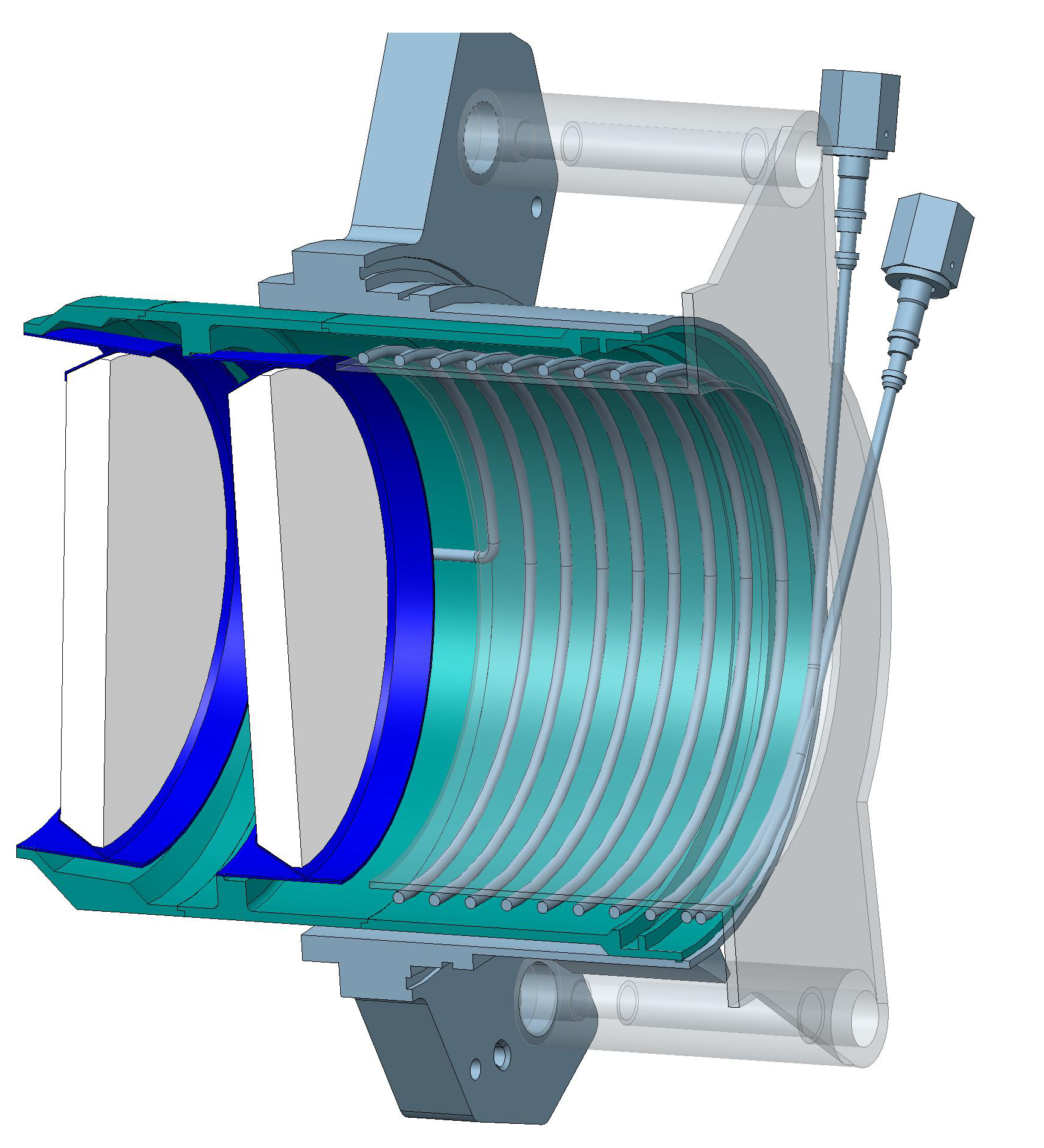
2.1 Free space propagation
This approach is inspired by what has been done on JET for the reflectometry and ECE transmission lines [5]. Bolted and welded double window assemblies have been designed. They will be installed on the closure plate at the back of the diagnostic port-plugs as shown on Figure 1 for the ECE and LFS-R systems. A Gaussian beam telescope will be used to transmit the microwaves through the windows. Antenna on the air-side is aligned with the vacuum-side optic (waveguide or mirrors) and the double vacuum windows using elliptical mirrors. The impact of high power stray microwave radiation [6] on theses windows is being assessed.
2.2 In-waveguide
In the case of in-waveguide vacuum barriers, the double windows are embedded into the waveguide. Figure 2 shows one conceptual design to position the reflectometry in-waveguide windows close to the upper-port feed-outs.
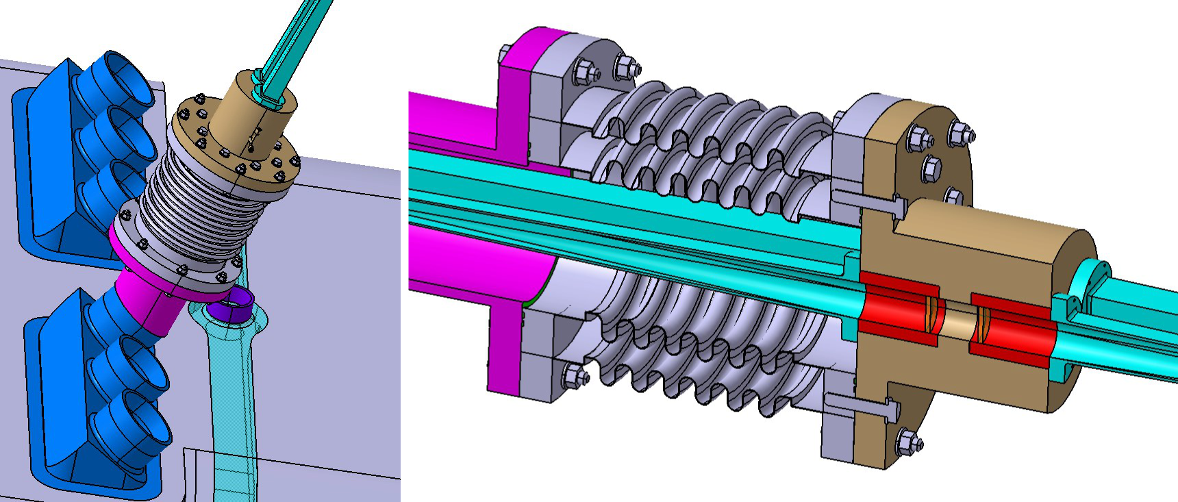
For this design, the microwave performance is checked by doing numerical simulations. The losses simulated without any optimisation were between 2 and . Mock-ups are also being manufactured for leak, thermal stress and microwave transmission tests.
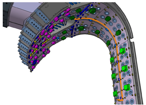
3 In-vessel waveguides
For HFS-R and PPR, waveguides are used to route microwaves between windows and antennas through the vacuum vessel. Space available being tight, the route has to be carefully designed in order not to jeopardise measurements made through these small waveguides. Some lines of sight are using an antenna on the inboard side of the vacuum vessel. The waveguides are running for almost along the vacuum vessel from the upper ports of ITER as shown in Figure 3. The space available is limited as the nominal gap between the vacuum vessel and the blankets is about . Special cutouts have to be made on the back of the blanket modules to allow the waveguides to run.
The internal section of the waveguides is smooth and rectangular, 12 by with a thickness of . Traditionally such waveguides are in copper but this cannot be done in ITER because of the large electro-magnetic loads appearing during disruptions. To reduce the intensity of these forces, stainless steel is used as its conductivity is much lower than copper. In order to retain the microwave performance, a thin layer (less than ) of copper is deposed on the waveguide inner surfaces. This design is a challenge to manufacture but some pieces have already been produced by RF-DA. The copper adherence was good but microwave performance is still being improved. The maximum length expected to be produced is about . Flanges will be used to assemble the complete run.
Waveguides run in pairs as one is used for emission and one for reception. A casing has also to be added in order to strengthen the waveguides and allow them to cope the electro-magnetic loads. The final section of the whole assembly is about 26 by . To avoid mode conversion in order to keep acceptable microwave performance, the waveguides must stay within the poloidal plane. Assembly will thus be challenging as the maximum deviation to this plane is only per meter in the toroidal direction.
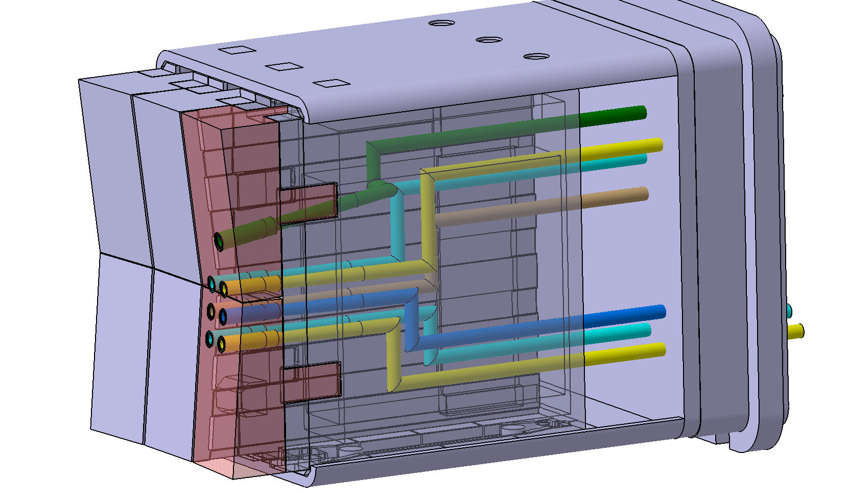
ECE, CTS and some reflectometry systems will also be installed in diagnostic port-plugs [7] where more space is available. Depending on the system, quasi-optics or over-sized corrugated waveguides will be used. The circular waveguide inner-diameters will be 31.75, 50.8 or . Mitre bends are used to create simple labyrinth in order to avoid straight lines allowing neutron streaming as shown in Figure 4. Nevertheless, neutron fluence will induce material activation and all the port plug components will be maintained using remote handling tools.
4 Antennas
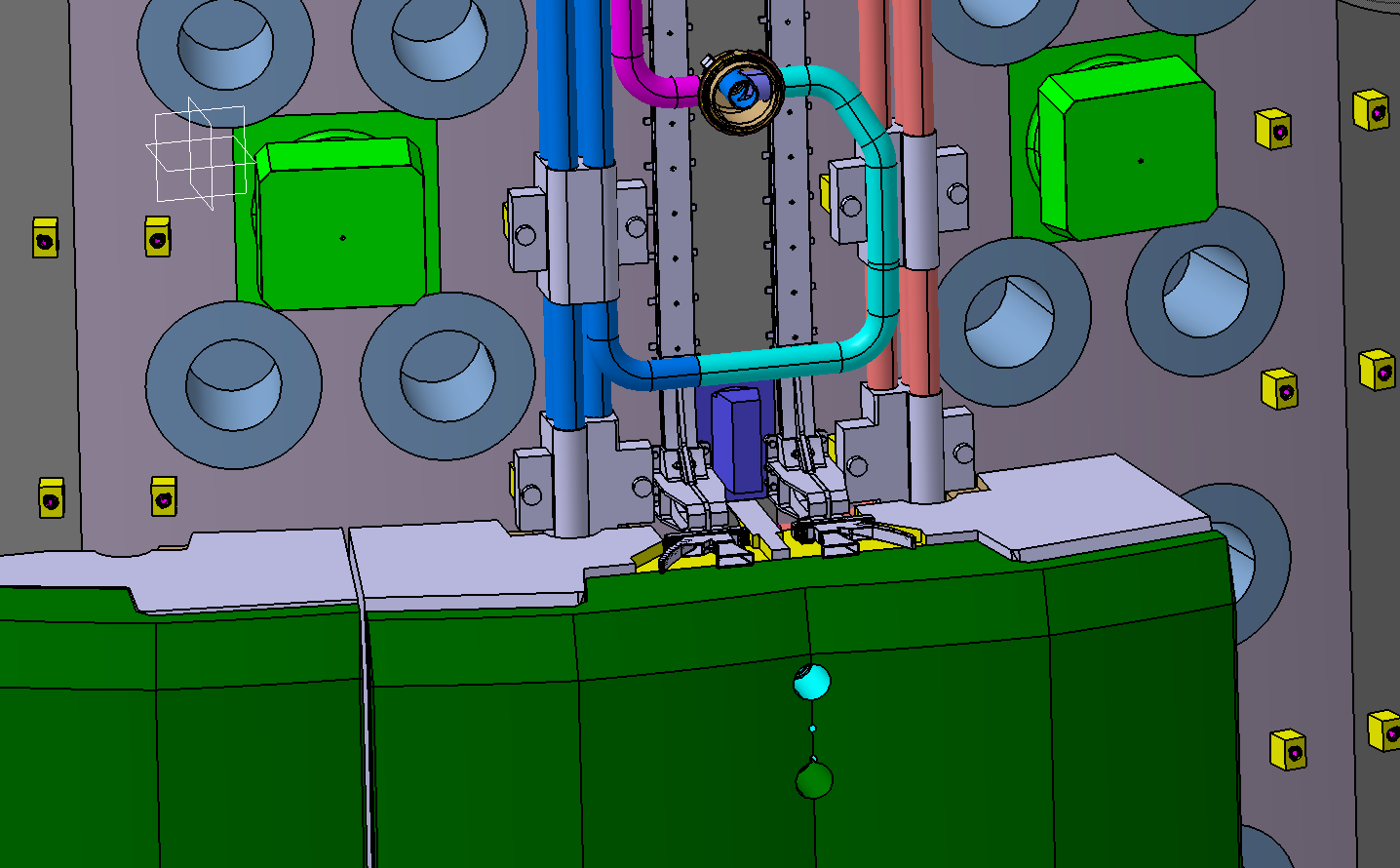
Depending on their position, antennas are facing different challenges. For the inner board reflectometry systems, a gap is allowed between two blanket modules in order to get a clear view to the plasma. The design of the antenna and its support has been constrained by the very tight space available as seen in Figure 5. The waveguide bend has been carefully designed to keep good microwave performance across the whole frequency band () and in both polarisations. Some attention has also been taken to avoid having too much current running in the bend structure during disruptions in order to minimise the electro-magnetic loads.
Where more space is available, such as in the outboard side, collection optic can be larger and recessed in the port plug. This is the case for the ECE and CTS diagnostics. For reflectometry, more lines of sight are required, and thus the last optics components cannot be recessed without posing problem in terms of heat flux handling and neutron shielding. In this case the waveguides are carrying the microwave up to first wall where the antenna mouth are installed as shown in Figure 4. Being close to the plasma the antennas need to be actively water cooled. Because of the amount of water required, the design has to observe the French regulation on pressurised equipment in a nuclear environment (ESPN) [8].
5 Summary and future work
While microwave diagnostic components require great attention for their design in order to obtain good performance, ITER environment brings additional constraints into the design: thermal and electro-magnetic loads, neutron activation, tritium containment, interface with other systems in a tight environment, microwave stray radiation and remote handling maintenance. Antenna, waveguide and vacuum window designs have followed these constraints.
Most of the components described here are in an intermediate design phase and are expected to go the final design phase in the next few year. Some mock-ups have already been manufactured and tested to check the designs fulfill the mechanical and thermal requirement, while keeping acceptable microwave performance. This activity is expected to intensify in the coming years. For the HFS-R and PPR systems, as they run along the vacuum vessel, the main present activity is to consolidate the assembly sequence in agreement with the blanket systems.
The views and opinions expressed herein do not necessarily reflect those of the ITER Organization. This publication reflects the views only of the author, and Fusion for Energy cannot be held responsible for any use which may be made of the information contained therein.
References
References
- [1] G. Vayakis, et al., Status and prospects for mm-wave reflectometry in ITER, Nuclear Fusion 46 (9) (2006) S836.
- [2] E. Mazzucato, Microwave reflectometry for magnetically confined plasmas, Review of Scientific Instruments 69 (6) (1998) 2201–2217.
- [3] V. S. Undintsev, et al., Progress in the development of the ITER ECE diagnostic, Fusion Science and Technology 59 (4) (2011) 678–683.
- [4] H. Bindslev, et al., Fast-ion dynamics in the TEXTOR tokamak measured by collective thomson scattering, Plasma Physics and Controlled Fusion 49 (12B) (2007) B551.
- [5] L. Cupido, et al., New millimeter-wave access for JET reflectometry and ECE, Fusion Engineering and Design 74 (1–4) (2005) 707 – 713.
- [6] J. W. Oosterbeek, et al., Loads due to stray microwave radiation in ITER, in: this conference, 2014.
- [7] C. Pitcher, et al., Nuclear engineering of diagnostic port plugs on ITER, Fusion Engineering and Design 87 (5–6) (2012) 667 – 674.
- [8] T. Giacomin, et al., Engineering requirements due to the ESP/ESPN regulation apply at the port plug for ITER diagnostic system, in: this conference, 2014.