Spin Textures of Polariton Condensates in a Tunable Microcavity with Strong Spin-Orbit Interaction
Abstract
We report an extended family of spin textures in coexisting modes of zero-dimensional polariton condensates spatially confined in tunable open microcavity structures. The coupling between photon spin and angular momentum, which is enhanced in the open cavity structures, leads to new eigenstates of the polariton condensates carrying quantised spin vortices. Depending on the strength and anisotropy of the cavity confinement potential and the strength of the spin-orbit coupling, which can be tuned via the excitonic/photonic fractions, the condensate emissions exhibit either spin-vortex-like patterns or linear polarization, in good agreement with theoretical modelling.
pacs:
Quantized vortices are topological defects occurring in many physical systems in optics, condensed matter, cosmology and fundamental particles, characterized by a phase winding of an integer multiple of around a vortex core. In semiconductor microcavities, quantized vortices Lagoudakis et al. (2008); Nardin et al. (2011); Sanvitto et al. (2011) and vortex-antivortex pairs Keeling and Berloff (2008); Cancellieri et al. (2014); Hivet et al. (2014); Christmann et al. (2012) may form spontaneously in exciton-polariton superfluids and non-equilibrium polariton Bose-Einstein condensates (BECs). Much effort has been devoted to the development of methods to create orbital angular momentum(vortices) in polariton condensates, providing ways to study the fundamental physics of metastable currents or for potential use as quantum sensors G. Franchetti and Baumberg (2012) or information encoding devices Kapale and Dowling (2005). Optical imprinting Krizhanovskii et al. (2010) of vortices as well as robust spontaneous vortices using chiral polaritonic lenses Dall et al. (2014) have been demonstrated. Interestingly, the coherent coupling of the photon pseudo-spin (polarization) with vortex orbital angular momentum has been shown to lead to new types of topological entities, named spin vortices, characterised by quantised spin current instead of phase winding. Uncontrolled spontaneous spin vortices were reported in atomic spinor BECsSadler et al. (2006) and in polariton condensates subject to structural disorderManni et al. (2013), although the exact origin of the polariton spin currents remains unclear. We also note that the degrees of freedom associated with both the orbital angular momentum and the polarization of a photon may find useful applications in quantum information processing Mair et al. (2001); Nagali et al. (2009); Khoury et al. (2013).
More recently, considerable attention has been focused on the investigation of polariton spin-orbit (SO) coupling, i.e. the interaction between the polariton orbital motion and its spin due to the effective magnetic field induced by the transverse-electric transverse-magnetic (TE-TM) splitting characteristic of semiconductor microcavities Panzarini et al. (1999). In condensed matter SO coupling has led to significant physical phenomena such as the spin-Hall effect Kato et al. (2004) and topologically protected conducting states Hasan and Kane (2010), whereas in optical microcavities, SO coupling of exciton-polaritons enables observations of interesting optical counterparts, including the optical spin-Hall effect Leyder et al. (2007), magnetic-monopole-like half-solitons Hivet et al. (2012) and possibly topological insulators Lu et al. (2014); Nalitov et al. (2014).
In this paper we demonstrate polariton condensation in our recently developed tunable open microcavity system Dufferwiel et al. (2014), where a top concave mirror creates a zero-dimensional confinement potential for polaritons. Multiple coexisting condensates are observed under non-resonant pumping exhibiting an extended family of spin vortices and textures. These effects are associated with the strong SO coupling in the open cavity system consisting of semiconductor bottom and dielectric top Bragg mirrors separated by an air gap. We observe condensate emissions showing both spin-vortex-like patterns as well as linearly-polarised states. The resultant condensate polarization patterns depend on the interplay between the strength and the anisotropy of the confinement potential and the strength of the SO coupling, which can be modified with change of exciton/photon fraction. We note that polariton condensates exhibiting less rich spin vortex phenomena were observed in a geometry of photonic micropillars coupled in a hexagonal pattern Sala et al. (2014).
The open microcavity system consists of planar bottom distributed Bragg reflectors (DBR) and a concave top DBR (see Supplementary Information Sup ) controlled independently by nanopositioners (top-left inset of Fig. 1), which allows free tuning of the spectral resonance by changing the mirror separation Dufferwiel et al. (2014). A total number of 12 GaAs quantum wells (QWs) are grown above the surface of the bottom DBR at electric field antinodes, allowing the strong exciton-cavity coupling regime to be reached with a Rabi splitting of meV Sup . Polariton condensation is demonstrated with nonlinear increase of emission intensity, sharp linewidth reduction and a small blueshift ( meV) far below the bare cavity mode at meV to higher energy Sup .
The top concave mirror induces a strong and almost harmonic lateral confinement of the polariton condensateDufferwiel et al. (2014). For this reason the system eigenmodes are studied in the basis of Laguerre-Gauss modes with the SO coupling or the asymmetries in the circular shape of the top mirror included perturbatively Sup . In order to fully describe the eigenmodes of the system two bases of Laguerre-Gauss modes are needed, one for each pseudo-spin component: , where represent polaritons associated with left/right circularly polarized light, and and are quantum numbers quantifying the radial and azimuthal phase evolution, respectively.
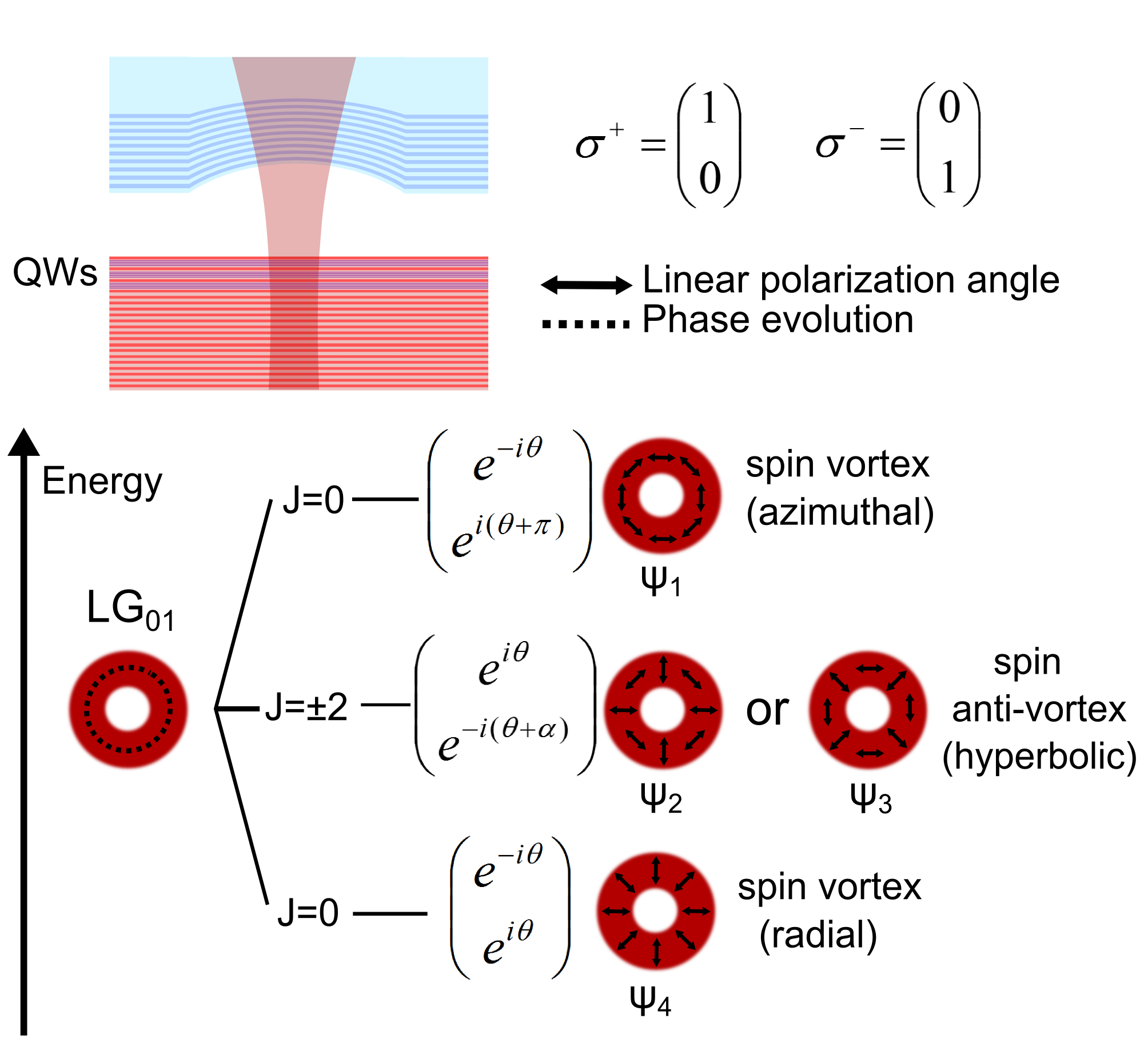
We consider the simplest case of perfectly circular mirrors. Since only Laguerre-Gauss modes with carry non zero orbital angular momentum , corresponding to a phase rotation of either clockwise (phase vortex) or anti-clockwise (phase anti-vortex), our analysis starts from the first excited manifold (FEM) of the harmonic potential (without SO coupling):
where is the azimuthal part of the polariton wavefunction with for polaritons associated with polarized light, is its radial part, and and are angular and radial coordinates. , with the lower-polariton mass and the strength of the confining harmonic potential. Using degenerate perturbation theory and including the SO interaction, one obtains the following new eigenmodes (see Sup ):
| (1) |
with eigenenergies: , , and , where is the energy of the mode and is a parameter describing the strength of the SO coupling Sup . The structure of the new eigenmodes, illustrated in Fig. 1, can be understood by observing that in the presence of SO coupling the conserved quantity of the system is the total angular momentum . Since and are both equal to either or the new possible eigenmodes have total angular momentum or . The SO coupling lifts the degeneracy by coherently combining the wavefunctions ( and ) to form new eigenstates, while leaving the energy of the two modes unaffected. For these any linear combination of and is a suitable eigenmode in the presence of SO coupling.
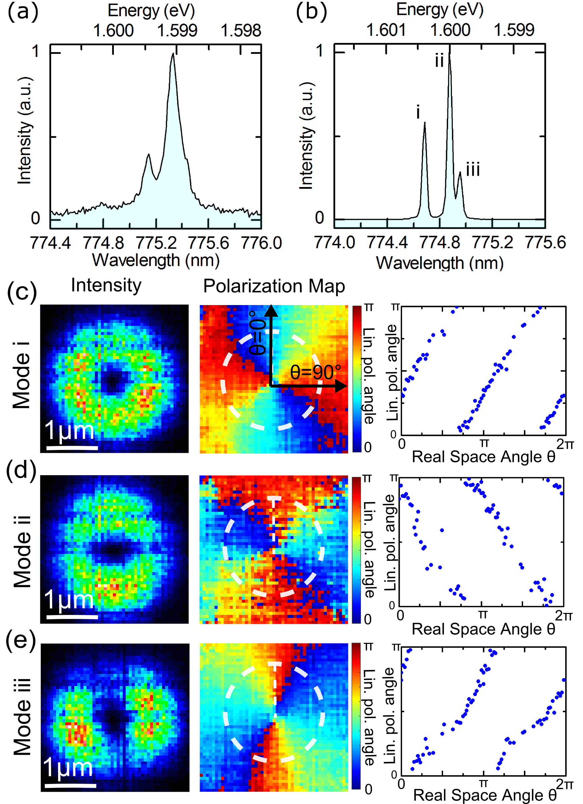
To investigate the properties of spin vortices low temperature photoluminescence (PL) measurements were carried out (details in Sup ). In the first set of measurements, a concave mirror with a radius of curvature (RoC) of 20 µm was employed and the mirror separation was µm. The cavity is detuned so that polaritons in the FEM modes have a photonic fraction of %. Below the condensation threshold, the spectrum associated with the FEM displays two broad features, as shown in Fig. 2 (a). With increase of pump power, condensation occurs and the linewidths drop sharply due to an increase of temporal coherence. Three well-resolved modes labelled by i, ii and iii are now revealed in Fig. 2 (b). Energy resolved images, shown in the left panels of Fig. 2 (c),(d) and (e), show a ring-like field distribution for all the three modes. The imperfection of the ring shape of mode iii is due to slight asymmetry of the confinement potential as will be discussed later. A linear polariser and a quarter wave plate are inserted into the optical path to collect polarization and energy resolved images for each mode in the horizontal-vertical ( ) basis, diagonal () basis and circular () basis, and the associated Stokes parameters, , and , are calculated for each pixel of the image Sup . The linear polarization angle , defined as , is mapped out for each mode in the middle panels of Fig. 2 (c),(d) and (e). As the circular polarization degree () is low for all the three modes Sup , the linear polarization vectors characterize well the spin textures.
All three modes display quantised pseudospin currents characterized by a rotation of around the mode cores, with a high linear polarization degree being exhibited. For both modes i and iii, changes nearly linearly with the real space azimuthal angle , corresponding to the rotation of the vector of linear polarization clockwise around the mode centre, which indicates a co-rotating relation between and , as indicated by the right panels of Fig. 2 (c) and (e). At , we observe (horizontal polarization) for mode i and (vertical polarization) for mode iii ( is defined as vertical, see the middle panel of Fig. 2 (c)), showing they are azimuthal and radial spin vortices corresponding to the extremal modes and in Fig. 1, respectively. By contrast, mode ii is a spin anti-vortex displaying the opposite pseudospin vector rotation with respect to i and iii, with and counter-rotating (right panel Fig. 2 (d)). As discussed in Manni et al. (2013), its hyperbolic-like polarization pattern results from the coherent combination, with any initial phase difference, of half-vortices with different polarization (modes and in Fig. 1 correspond to the case with a phase difference of or ). The energy splitting of meV observed between modes i and iii indicates strong SO interaction, consistent with transfer matrix simulations performed for the case of a planar open cavity revealing values of TE-TM splitting at high momenta of meV. Such a large value mainly arises from the phase shifts due to reflections at the air gap interfaces in the open cavity system. Possible reasons for the unequal energy spacing between modes i, ii and iii are discussed in Sup .
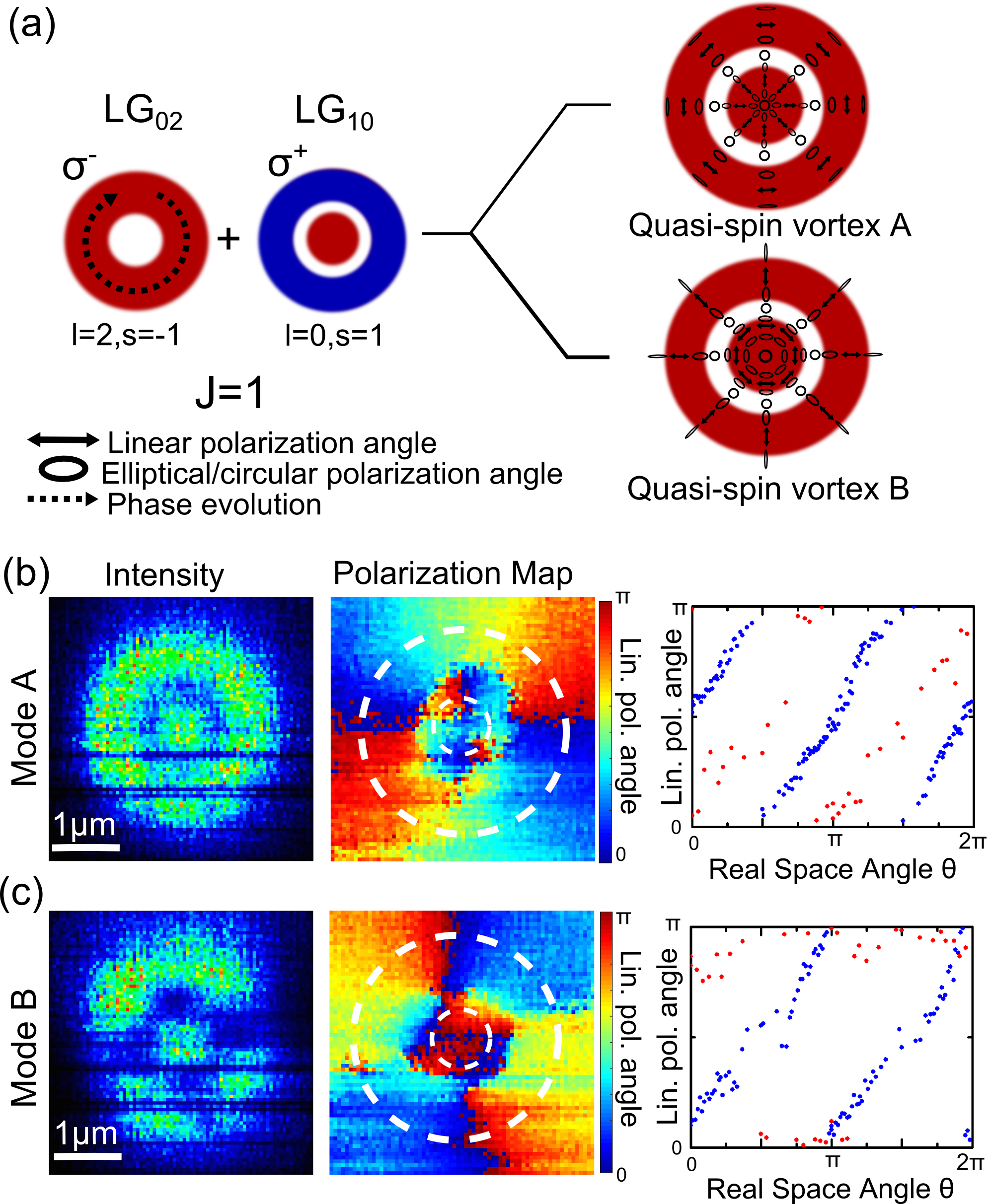
We also observe spin textures for polaritons condensed into higher order LG-associated modes, when these are tuned into resonance with the exciton. Similar to the case, SO coupling also mixes modes in the second excited manifold like, for example, and modes. As illustrated in Fig. 3 (a), the modes formed are quasi-spin vortices labelled as type A and B. The polarization vectors exhibit radial (A) or azimuthal (B) spin vortex character in the inner core and azimuthal (A) or radial (B) spin vortex character in the outer ring, connected by transient elliptically polarised states. Such quasi-spin vortices of polariton condensates were experimentally observed as shown in Fig. 3 (b) and (c), with a change of linear polarization angle of between the inner core and outer ring. Here above condensation threshold four spectrally resolved condensates are observed and for simplicity we show polarization patterns only for two of them, which fully demonstrate the principle illustrated in Fig. 3 (a). The imperfection of the mode spatial profile and the linear-like polarization vector of the inner core in Fig. 3 (c) compared to (a) are most likely due to the slightly elliptical shape of the top concave mirror.
If the concave top mirror has a sufficiently strong ellipticity which perturbs the harmonic confinement potential along the two orthogonal directions with strength (see Sup for details) it may induce Mathieu-Gauss (MG) modes Gutierrez-Vega et al. (2003); Nardin et al. (2010) which are characterised by linearly-polarised orthogonal double-lobe profiles (See Fig. 4(d)). The eigenmodes of the cavity arise from the competition between the asymmetry of the mirror and the strength of the SO coupling: either spin vortices or linear polarised states will be formed depending on which term dominates. In order to demonstrate condensation in MG modes the strength of SO coupling can be reduced by tuning the energy of the condensed modes closer to the exciton, and mirrors with smaller RoC chosen where the confinement potential is stronger and the spatial anisotropy is more pronounced.
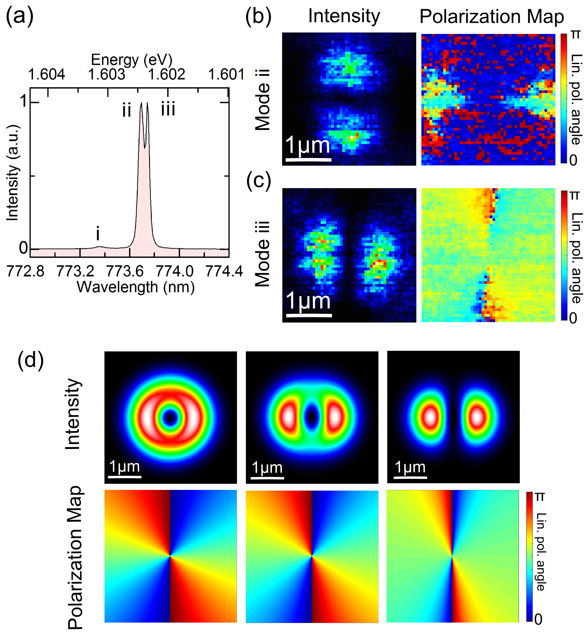
From these considerations a concave mirror with a RoC of µm is chosen, and a photon fraction of 41% employed. Fig. 4 (a) shows the spectrum of the polariton condensate associated with the FEM, where the low energy modes ii and iii are preferentially selected above threshold leading to significantly larger intensity than mode i. Non-trivial differences, compared to the spin vortices in Fig. 2, are found in the mode spatial profiles and polarization patterns, as shown in Fig. 4 (b) and (c) for mode ii and iii. Instead of being spin vortices/anti-vortices, modes ii and iii clearly show MG-like orthogonal double-lobe profiles (left panels) with vertical (ii) and horizontal (iii) linear polarization (right panels). The simulated intensity distribution and polarization maps of one of the eigenstates confined in an elliptical potential are shown in Fig. 4 (f) for decreasing TE-TM splitting factors. Theoretically, it is seen that smaller SO coupling leads to the MG mode being the eigenstates of the system as the ellipticity term has greater influence. Importantly, for the same RoC= µm mirror, we can recover the vortex-like spin textures for all three modes similar to those shown in Fig. 2 by doubling the photonic fraction up to 82%, as shown in the supplementary material Sup . In addition, as expected this enhancement of SO coupling with increase of the photon fraction results in increase of the i-ii mode splitting from 0.71 meV to 1.02 meV. This demonstrates the advantages of the tunability of the open cavities in permitting the degree of the light/matter fractions of the cavity polaritons to be varied but also in allowing flexible manipulation of the condensate polarization textures.
In summary, we have demonstrated polariton condensate emission exhibiting spin vortices and more elaborate spin textures in a tunable microcavity system with lateral confinement. We note that below threshold the tomographic energy-resolved images of broad polariton modes also exhibit spin-vortex structures, but not all patterns are observed due to the lack of spectral resolution. In order to reveal the complete mode structure it is important to be in the regime of condensation where the temporal coherence is increased. Our observations are promising for optical information applications involving photon orbital angular momentum and polarization Kapale and Dowling (2005) and are interesting for further studies on cavity quantum electrodynamics (CQED) involving polaritonic spin.
We acknowledge support by EPSRC grant EP/J007544, ERC Advanced Grant EXCIPOL and the Leverhulme Trust.
References
- Lagoudakis et al. (2008) K. G. Lagoudakis, M. Wouters, M. Richard, A. Baas, I. Carusotto, R. Andre, L. S. Dang, and B. Deveaud-Pledran, Nat Phys 4, 706 (2008).
- Nardin et al. (2011) G. Nardin, G. Grosso, Y. Léger, B. Piȩtka, F. Morier-Genoud, and B. Deveaud-Plédran, Nature Physics 7, 635 (2011).
- Sanvitto et al. (2011) D. Sanvitto, S. Pigeon, A. Amo, D. Ballarini, M. De Giorgi, I. Carusotto, R. Hivet, F. Pisanello, V. G. Sala, P. S. S. Guimaraes, R. Houdre, E. Giacobino, C. Ciuti, A. Bramati, and G. Gigli, Nat Photon 5, 610 (2011).
- Keeling and Berloff (2008) J. Keeling and N. G. Berloff, Phys. Rev. Lett. 100, 250401 (2008).
- Cancellieri et al. (2014) E. Cancellieri, T. Boulier, R. Hivet, D. Ballarini, D. Sanvitto, M. H. Szymanska, C. Ciuti, E. Giacobino, and A. Bramati, Phys. Rev. B 90, 214518 (2014).
- Hivet et al. (2014) R. Hivet, E. Cancellieri, T. Boulier, D. Ballarini, D. Sanvitto, F. M. Marchetti, M. H. Szymanska, C. Ciuti, E. Giacobino, and A. Bramati, Phys. Rev. B 89, 134501 (2014).
- Christmann et al. (2012) G. Christmann, G. Tosi, N. G. Berloff, P. Tsotsis, P. S. Eldridge, Z. Hatzopoulos, P. G. Savvidis, and J. J. Baumberg, Phys. Rev. B 85, 235303 (2012).
- G. Franchetti and Baumberg (2012) N. B. G. Franchetti and J. Baumberg, Arxiv 1210.1187, 1210.1187 (2012).
- Kapale and Dowling (2005) K. T. Kapale and J. P. Dowling, Physical Review Letters 95, 173601 (2005).
- Krizhanovskii et al. (2010) D. N. Krizhanovskii, D. M. Whittaker, R. A. Bradley, K. Guda, D. Sarkar, D. Sanvitto, L. Vina, E. Cerda, P. Santos, K. Biermann, R. Hey, and M. S. Skolnick, Physical Review Letters 104, 126402 (2010).
- Dall et al. (2014) R. Dall, M. D. Fraser, A. S. Desyatnikov, G. Li, S. Brodbeck, M. Kamp, C. Schneider, S. Höfling, and E. A. Ostrovskaya, Phys. Rev. Lett. 113, 200404 (2014).
- Sadler et al. (2006) L. E. Sadler, J. M. Higbie, S. R. Leslie, M. Vengalattore, and D. Stamper-Kurn, Nature 443, 312–315 (2006).
- Manni et al. (2013) F. Manni, Y. Léger, Y. G. Rubo, R. André, and B. Deveaud, Nat Commun 4 (2013), 10.1038/ncomms3590.
- Mair et al. (2001) A. Mair, A. Vaziri, G. Weihs, and A. Zeilinger, Nature 412, 313 (2001).
- Nagali et al. (2009) E. Nagali, F. Sciarrino, F. De Martini, L. Marrucci, B. Piccirillo, E. Karimi, and E. Santamato, Physical Review Letters 103, 013601 (2009).
- Khoury et al. (2013) A. Z. Khoury, C. E. R. Souza, A. R. Vieira, and M. O. Hor-Meyll, in SPIE NanoScience + Engineering, edited by H.-J. Drouhin, J.-E. Wegrowe, and M. Razeghi (International Society for Optics and Photonics, 2013) p. 881310.
- Panzarini et al. (1999) G. Panzarini, L. C. Andreani, A. Armitage, D. Baxter, M. S. Skolnick, V. N. Astratov, J. S. Roberts, A. V. Kavokin, M. R. Vladimirova, and M. A. Kaliteevski, Phys. Rev. B 59, 5082 (1999).
- Kato et al. (2004) Y. K. Kato, R. C. Myers, A. C. Gossard, and D. D. Awschalom, Science (New York, N.Y.) 306, 1910 (2004).
- Hasan and Kane (2010) M. Z. Hasan and C. L. Kane, Reviews of Modern Physics 82, 3045 (2010).
- Leyder et al. (2007) C. Leyder, M. Romanelli, J. P. Karr, E. Giacobino, T. C. H. Liew, M. M. Glazov, A. V. Kavokin, G. Malpuech, and A. Bramati, Nat Phys 3, 628 (2007).
- Hivet et al. (2012) R. Hivet, H. Flayac, D. D. Solnyshkov, D. Tanese, T. Boulier, D. Andreoli, E. Giacobino, J. Bloch, A. Bramati, G. Malpuech, and A. Amo, Nature Physics 8, 724 (2012).
- Lu et al. (2014) L. Lu, J. D. Joannopoulos, and M. Soljačić, Nature Photonics 8, 821 (2014).
- Nalitov et al. (2014) A. Nalitov, D. Solnyshkov, and G. Malpuech, (2014), arXiv:1409.6564 [cond-mat.mes-hall] .
- Dufferwiel et al. (2014) S. Dufferwiel, F. Fras, A. Trichet, P. M. Walker, F. Li, L. Giriunas, M. N. Makhonin, L. R. Wilson, J. M. Smith, E. Clarke, M. S. Skolnick, and D. N. Krizhanovskii, Applied Physics Letters 104, (2014).
- Sala et al. (2014) V. G. Sala, D. D. Solnyshkov, I. Carusotto, T. Jacqmin, A. Lemaître, H. Terças, A. Nalitov, M. Abbarchi, E. Galopin, I. Sagnes, J. Bloch, and A. Malpuech, G.and Amo, Arxiv 1406.4816, 1406.4816 (2014).
- (26) See supplementary material .
- Gutierrez-Vega et al. (2003) J. C. Gutierrez-Vega, R. M. Rodriguez-Dagnino, M. A. Meneses-Nava, and S. Chavez-Cerda, Am. J. Phys 71 (2003).
- Nardin et al. (2010) G. Nardin, Y. Léger, B. Pietka, F. Morier-Genoud, and B. Deveaud-Plédran, Physical Review B 82, 45304 (2010).
- Dolan et al. (2010) P. R. Dolan, G. M. Hughes, F. Grazioso, B. R. Patton, and J. M. Smith, Opt. Lett. 35 (2010).
- Wertz et al. (2010) E. Wertz, L. Ferrier, D. D. Solnyshkov, R. Johne, D. Sanvitto, A. Lemaitre, I. Sagnes, R. Grousson, A. V. Kavokin, P. Senellart, G. Malpuech, and J. Bloch, Nature Physics 6, 860 (2010).
- Bajoni et al. (2008) D. Bajoni, P. Senellart, E. Wertz, I. Sagnes, A. Miard, A. Lemaître, and J. Bloch, Physical Review Letters 100, 47401 (2008).
Supplementary Information for “Spin Textures of Polariton Condensates in a Tunable Microcavity with Strong Spin-Orbit Interaction”
I Sample preparation and experimental set-up

The open microcavity system used to perform the experiments consists of a 31-pair Al0.2Ga0.8As/Al0.95Ga0.05As bottom distributed Bragg reflector (DBR) with a near-surface active region and an 11-pair SiO2/TiO2 circular-shaped concave top DBR separated by a micrometer sized gap. Arrays of concave mirrors are fabricated through focused ion beam (FIB) milling of a planar SiO2 substrate before coating with dielectric layers Dolan et al. (2010). The radii of curvature of the concave mirrors used in this work were 20 µm and 7 µm and can confine the polariton mode down to 1-2 µm. Nanopositioners allow independent positioning of both DBRs to form a planar-concave cavity where the spectral resonance can be tuned by changing the separation between them (Fig. S1, left inset) Dufferwiel et al. (2014). In the cavities used for this experiment, three sets of four 7 nm GaAs quantum wells (QWs) are embedded in the active region at the antinode of the optical field to enhance the exciton-photon coupling.
The experimental setup is shown in Fig. S1. The cavity system is placed in a vacuum tube with a small amount of He exchange gas which is immersed in a liquid helium dewar. Optical access to the cavity is provided by placing an optical table on top of the dewar. The sample is non-resonantly excited at 630 nm, close to a stopband minimum, with a spot size of 30 µm on the top mirror surface. The beam is reflected into the dewar by a beam splitter (BS) to an objective lens above the sample (NA=0.55) and the photoluminescence from the cavity is collected along the same optical path. The final image is sent to the end facet of a wound fibre bundle (WF) consisting of a x mm array of single mode fibres, which is imaged onto the spectrometer slits. It should be noted that light is depolarized by the WF, avoiding any measurement error possibly induced by the polarization-associated efficiency of the spectrometer mirror/gratings. Fig. S1 represents the setup used for k-space imaging, where lenses are located both in the dewar and on the optical table to form a confocal imaging system which projects the k-space image onto the WF facet. This setup can be easily altered for real-space imaging by simply replacing the two lenses on the optical table by one that focuses the real space image on to the WF facet, as used for our studies on spin vortices. A linear polarizer, whose polarization axis can be varied by motor-controlled rotation, is inserted before the WF to obtain polarization-resolved images, while adding a plate enables acquisition in circular polarization basis.
II Demonstration of strong coupling

The strong coupling of the 0-dimensional (0D) cavity is demonstrated by scanning the PL spectrum with varying cavity length, as shown in Fig. S2. The cavity length is decreased by applying a DC voltage to the bottom z-nanopositioner, raising the bottom sample closer to the top mirror. The change in cavity length as a function of applied piezo voltage is closely linear for voltages less than V. The lower polariton branch (LPB) shows strong curvature as a function of voltage arising from anti-crossing with the exciton energy, the signature of strong exciton-cavity coupling. The upper polariton branch (UPB) is not observed due to the strong absorption induced by the excitonic continuum of the 12 GaAs quantum wells. Fitting the LPB dispersion curve of the mode with a coupled oscillator model gives a Rabi splitting of meV, in good agreement with theoretical and experimental values reported in similar structures Wertz et al. (2010); Bajoni et al. (2008).

The Rabi splitting can also be estimated from the 2-dimensional polariton dispersion. As shown in Fig. 1(a) of Reference Dufferwiel et al. (2014) the top DBR contains planar regions around the arrays of concave features. The formation of a planar-planar cavity using this region gives rise to two-dimensional polaritons. Fig. S3 (a) and (b) shows the angular dispersion of the planar open cavity at two-different detunings of meV and meV. In both cases the LPB can be fitted with the expected Rabi splitting of meV, in agreement with previous full microcavities containing similar numbers of QWs Wertz et al. (2010); Bajoni et al. (2008).
III Polariton Condensation
Polariton condensation into the first excited manifold (FEM) of states is characterized in Fig. S4. Non-linearity of output intensity and sharp linewidth reduction is observed. The blueshift at threshold, meV, is significantly less than the which is meV, showing that the cavity is in the strong coupling regime above threshold. The spectra below and above threshold are in Fig. 2 (a) and (b) of the main text.

IV Experimental determination of the Stokes parameters
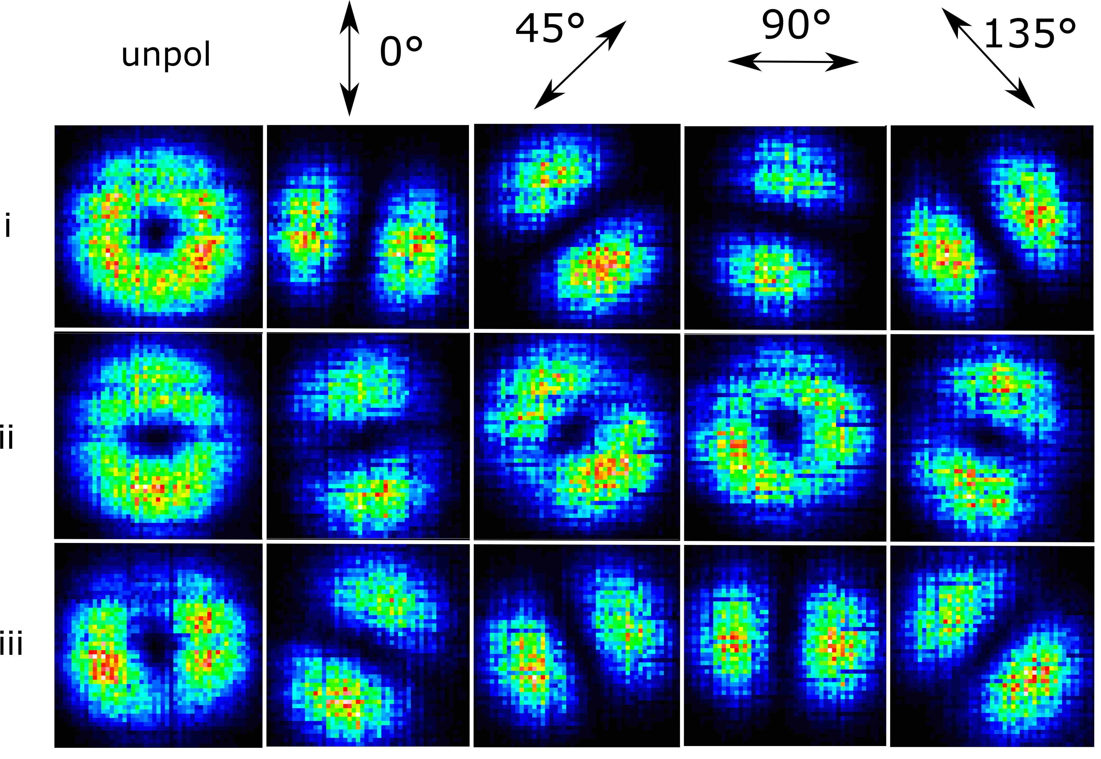
In our experiment polarization-resolved images are taken in order to obtain the spatial intensity distribution in the horizontal-vertical ( and ), diagonal ( and ) and circular () bases. Fig. S5 shows the clear rotation of the intensity distribution as a function of the linear polarizer angle. Modes i and iii show orthogonally positioned lobes co-rotating with the polarizer axis while mode ii anti-rotates with the polarizer axis. This indicates the formation of spin vortices for modes i and iii and spin anti-vortices for mode ii. Stokes parameters for horizontal-vertical (), diagonal () and circular () basis are obtained for each spatial pixel of the mode by
where is the measured intensity in various polarization basis. The polarization angle in real space , is obtained from , as the winding angle in the - plane of the Stokes presentation is twice of that in real space. Fig. S6 shows the Stokes parameters derived for the spin vortices in Fig. 2 of the main text.

V Spin vortices with a top mirror of ROC= µm
The mode spatial profiles and polarization patterns with the RoC= µm top mirror with a high photonic fraction (82% photon-like) are shown in Fig. S7. Azimuthal, radial and hyperbolic spin vortices are revealed, similar to Fig. 2 but contrasting sharply with Fig. 4 of the main text taken at 41% photon fraction where the ellipticity perturbation plays a larger role relative to the SO interaction.

VI Theoretical Model
We present here the theoretical approach used to interpret the experimental data. In our approach we use degenerate perturbation theory to find the eigenmodes of the polariton system in the case of low polariton densities (i.e. when the nonlinearities play a negligible role) in the presence of SO coupling, elliptical shape of the top concave mirror and birefringence from the anisotropy of the refractive index of the top mirror. Taking the eigenvectors and to represent circularly polarised polaritons, the 2x2 Hamiltonian describing the lower-polariton branch in the linear regime can be written as:
| (S1) |
where is the lower-polariton effective mass. The terms depending on , where are the lower-polariton masses in the TE/TM polarizations, describe the TE-TM splitting. As pointed out in Dufferwiel et al. (2014) the top concave mirror induces a strong near-harmonic lateral confinement potential. , where is the strength of the harmonic confinement. The terms account for an elliptical asymmetry of the top circular mirror with the long axis either aligned along the or directions. As birefringence may arise in both the top and bottom mirrors due to strain, the terms account for a birefringence that induces a shift at between the TE-TM branches and tends to align the field polarization along the direction .
Since the harmonic confinement is much stronger than the SO coupling, the birefringence and the asymmetry, one can treat these terms as perturbations. To study a 2-dimensional harmonic oscillator several equivalent eigenvector bases can be used. Among them two are particularly useful: the basis of Laguerre-Gauss modes (where and are radial and azimuthal quantum numbers) and the basis of Hermite-Gauss modes (where and are quantum numbers along the and axes). While the basis of LG modes allows a more intuitive understanding of the shape of the spin vortices, the basis of the HG modes allows an easier evaluation of the matrix elements needed to determine the perturbed eigenenergies and eigenmodes. For this reason, and since the perturbed eigenmodes and eigenenergies do not depend on the basis of the Hilbert space used to evaluate them, we use the basis of the HG modes to apply perturbation theory. In the case of the first excited manifold the four relevant HG modes are:
Using these modes as basis, the new perturbed eigenenergies and eigenmodes of the system are obtained by diagonalising the following matrix:
| (S2) |
where . The eigenmodes and eigenenergies of this matrix reduce to those of Equation (1) in the manuscript in the case of zero birefringence and no asymmetry in the harmonic confinement. For this particular case the energy spectra, the polariton density and the polarization angle for the four eigenmodes are plotted in figure S8. As expected, the higher (black) and the lower (red) modes are azimuthal and radial spin-vortices respectively, while the two remaining central modes (green and blue) are spin-antivortices in agreement with the experimental observations in fig 2 (c,d,e) in the main text.

The case of asymmetry and birefringence different from zero is plotted in Fig. S9. Clearly, the effect of these terms is to lift the degeneracy among the two central modes, thus breaking the symmetry of the spectra and inducing polaritons to polarise along a preferred direction. This is consistent with what it is observed in the experiments, although in the experiments the shape of the high-energy mode is generally less deformed by the asymmetry and birefringence than the low-energy modes. A possible explanation for this is that our theoretical model is based on the approximation of quadratic dispersion while in the polariton system the dispersion is strongly dependent on . Since the modes are strongly confined, high vectors are likely to play an important role. In addition exciton-exciton interactions and pump-decay mechanisms, both of which are not included in our model, may also lead to experimental/theory differences in the details of the patterns.

VII Spin textures generated from higher order LG modes

We derive the polarization patterns by superposing and . The result for the type A quasi-spin vortex in Fig.3 of the main text is shown in Fig. S10 as an example. The polarization pattern shows a radial spin vortex in the inner core and an azimuthal spin vortex in the outer ring, in good qualitative agreement with the experimental data shown in Fig. 3 (b) of the main text.