Few-cycle pulses from a graphene mode-locked all-fiber laser
Abstract
We combine a graphene mode-locked oscillator with an external compressor and achieve29fs pulses with52mW average power. This is a simple, low-cost, and robust setup, entirely fiber based, with no free-space optics, for applications requiring high temporal resolution.
Ultrafast light pulses in the femtosecond range are needed for advanced photonics applications. E.g. in pump-probe spectroscopy, photophysical and photochemical relaxation processes are monitored by exciting a sample with an ultrashort light pulse. The maximum temporal resolution is determined by the duration, , of the pulse. This is usually defined as the full width at half maximum (FWHM) of its intensity profile in the time domain, Fermann_ul . Alternatively may be defined by the number of oscillation periods of the electric field carrier wave (optical cycles) within the pulseKartner_fc , where is the optical cycle of frequency . The ultimate pulse duration is set by a single cycle of light, i.e. , given byKartner_fc , where is the wavelength and is the speed of light. Finally, the uncertainty relation provides a measure of the minimum frequency bandwidth required for an ultrashort pulse formationKartner_fc , i.e. the broader the bandwidth, the shorter the supported pulse. In the visible and near infrared (NIR), lies, e.g, between 2fs at 600nm and 5fs at 1.5m, which set the ultimate speed limit for devices operating in this wavelength range. Achieving shorter pulses therefore requires moving to shorter wavelengths.
Pulses as short as 2-cycles can be generated directly from laser cavities using passive mode-lockingKartner_fc ; Fermann_ul ; Keller03n . Ti:Saphire lasers have become established tools for few-cycle generationKartner_fc , with the shortest pulses produced to date having 5fsEll01ol at a centre wavelength, 800nm, corresponding to less than 2-cycles, with spectral width 600nmEll01ol . Ti:Saphire lasers able to generate few-cycle durations are typically optimized to make use of the maximum gain availableKartner_fc , consequently they have no wavelength tunabilityKartner_fc . Tunable Ti:Saphire operate with a much longer pulse duration, e.g. 150fs in a typical680-1080nm commercially available spectral rangeCoherent . Tunable few-cycle pulses can be achieved by exploiting nonlinear optical effects in optical parametric amplifiers (OPAs). These can be described by expressing the polarization () as a power series in the applied optical field ()Boyd_no ; Sutherland_hno : , where is the free space permittivity, is the linear and and are the second- and third-order nonlinear susceptibilities. OPAs are optical amplifiers based on the nonlinearity of a crystalBoyd_no ; Sutherland_hno ; Cerullo03rsi , in a process, called parametricBoyd_no ; Sutherland_hno , where there is no net transfer of energy and momentum between and the crystalBoyd_no ; Sutherland_hno . This can be visualized, by considering energy transfer from a pump pulse of frequency to two pulses of lower frequencies and , called signal and idlerBoyd_no ; Sutherland_hno , with the requirement Boyd_no ; Sutherland_hno . Under this condition, OPAs can transfer energy form a narrow, fixed , pump pulse, to a broad, variable , signal pulse, e.g. from600 to over 3500nm, with pulses as short as sub-3-cyclesBrida10jo ; Kartner_fc , their duration being ultimately limited by uncompensated dispersive and nonlinear effectsBrida10jo ; Kartner_fc . However, both Ti:Saphire oscillators and OPAs optimized to produce few-cycle pulses are complex and expensive setups, relying on bulk opticsKartner_fc ; Brida10jo . This has driven a research effort to find novel approaches, not only capable of producing short pulses, but also cheap, simple, broadband, and inexpensive, which would make few-cycle pulses more accessible to the wider scientific community.
Compared to their solid-state counterparts, fiber lasers are attractive platforms for short pulse generation due to their simple and compact designsFermann13np , efficient heat dissipationDausinger04tap , and alignment-free operationDausinger04tap ; Kartner_fc ; Fermann_ul . These characteristics, combined with advances in glass technologyDigonnet ; Russel03sc and nonlinear opticsDudley09np , resulted in systems working from the visible to the mid-infrared (MIR)Digonnet . In fiber oscillators, ultrashort pulses can be obtained by passive mode-lockingFermann13np . This typically requires the aid of a non-linear component called a saturable absorber (SA)Fermann_ul ; Keller03n ; Fermann13np . GrapheneHasan09am ; Sun10an and carbon nanotubes (CNTs)Scardaci08am ; Wang08nn ; Hasan09am have emerged as promising SAs for ultrafast lasersGoing12pe ; Wang08nn ; Woodward14ptl ; Zhang13oe ; Castellani13lpl ; Popa12apl ; Sun10an ; Sun10nr ; Popa11apl . In CNTs, broadband operation is achieved by using a distribution of tube diametersWang08nn ; Going12pe , while this is an intrinsic property of grapheneBonaccorso10np . This, along with the ultrafast recovery timeBrida13nc , low saturation fluenceSun10an ; Popa10apl , and ease of fabricationFerrari14ns and integrationBonaccorso12mt , makes graphene an excellent broadband SABonaccorso10np . Consequently, mode-locked lasers using graphene SAs (GSAs) have been demonstrated from800nmBaek12ape to 970nmZaugg13oe , 1mMary13oe , 1.5mPopa10apl and 2mZhang12oe up to 2,4mCizmeciyan13ol . Therefore, experimental setups that combine the unique optical properties and simple fabrication of graphene, with fiber lasers, are attractive prospects for few-cycle generation.
Here we achieve29fs pulses, corresponding to less than 6-cycles at 1550nm, using a graphene mode-locked fibre oscillator in conjunction with an external compressor based on an erbium doped fiber amplifier (EDFA) and a length of Single Mode Fibre (SMF). The EDF length within the amplifier acts as the gain and non-linear medium, used to simultaneously amplify and spectrally broaden the pulse, while the SMF, placed at the output of the EDFA, acts as the dispersive delay line. Our design uses only standard telecommunication equipment and an intrinsic broadband GSA, attractive when cost, ease of fabrication, and operational stability are required. In addition, this enables a compact and portable format.
For fiber lasers, a typical approach for ultrashort pulse generation is soliton mode-lockingKartner_fc ; Fermann_ul . In this regime, the fiber dispersive and non-linear effects can cancel each otherKartner_fc ; Fermann_ul , allowing a stable pulse envelope to propagateKartner_fc ; Fermann_ul . During propagation, the soliton periodically encounters perturbations occurring in the fiber laser of cavity length Agrawal_anfo . The shortest solitons stably supported, typically have Tamura93ol , where is the soliton period with the second-order dispersion. For pulses with 100fs, one needs 50cm for fiber lasers operating at 1.5m, where -25. For such short , it becomes challenging to compensate dispersive effects in all-fiber formatsAgrawal_anfo . E.g., to achieve pulses10-cycles, i.e.30fs at 1mBuckley06ol ; Zhou08oe ; Ma10ol , the shortest reported to dateZhou08oe ; Ma10ol , bulk optics are typically employedBuckley06ol ; Zhou08oe ; Ma10ol in order to compensate for dispersive effects, eliminating the advantage of alignment-free operation which makes fiber lasers attractive. A strategy to overcome these limitations in all-fiber laser formats is to use a dispersion-managed designNelson97apb ; Tamura93ol , where alternating segments of positive (or normal) and negative (or anomalous) dispersion fibers lead to periodic broadening and compression of the intracavity pulsesNelson97apb ; Tamura93ol . Compared to soliton mode-locking, the average can increase by an order of magnitude or more, which significantly reduces the intracavity , thus being less susceptible to nonlinear optical effectsNelson97apb ; Tamura93ol . However, in all-fiber oscillators, it is difficult to achieve the minimum , as set by . Dispersive effects increase with Agrawal_anfo and it is necessary to provide compensation for orders higher than , e.g. third-order dispersion or even higherAgrawal_anfo . In addition, the limited of gain fibers, typically50nmDigonnet_redfla , can further affect the minimum achievable . Thus, of particular interest are novel setups, still capable of few-cycle generation, but with simpler, more accessible designs, and ampler operation wavelength, maintaining the all-fibre design.
A different route for few-cycle generation is to externally compress the pulseKartner_fc ; Agrawal_anfo . In this approach, the pulse is first passed through a non-linear medium, such as a SMF lengthAgrawal_anfo , where it experiences self-induced phase modulation (SPM) (non-linear phase delay)Kartner_fc ; Agrawal_anfo , caused by its own intensity , via the Kerr effectAgrawal_anfo , i.e. -dependent change in the refractive index , where is the medium nonlinear index coefficientAgrawal_anfo . After a propagation length , the pulse accumulates a time dependent phase-shift Agrawal_anfo , resulting in the generation of new frequency components Kartner_fc ; Agrawal_anfo , distributed temporally across the pulse, i.e. the pulse becomes chirped. In order to achieve shorter , as supported by the now broadened , the chirped pulse is then passed through a dispersive delay lineAgrawal_anfo , which re-phases the new frequency components, , generated by the SPMKartner_fc ; Agrawal_anfo . Ideally, the dispersive delay line would introduce the inverse of the chirp added by SPM, resulting in the compression of the pulse to its minimum duration. Typically the dispersive delay line, formed by a component with negative dispersion, compensates for the linear chirp, around the central part of the pulse, where most energy is concentratedKartner_fc ; Agrawal_anfo . When compared to other techniques, such as OPAs, external pulse compression offers a more flexible designKartner_fc , with the possibility of taking advantage of the ultra-broadband spectrum which can be generated by the phase modulation processesKartner_fc ; Agrawal_anfo in all-fiber formatsAgrawal_anfo .
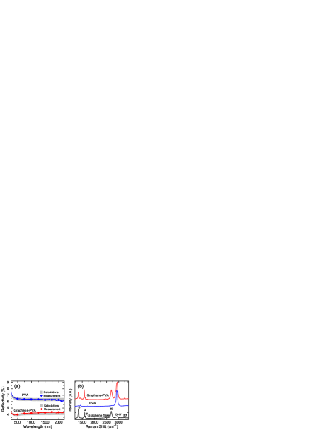
We use a graphene-PVA composite as our GSA, fabricated via solution processing. Graphite flakes are exfoliated from bulk graphite by mild ultrasonication with sodium deoxycholate (SDC) surfactantSun10an ; Bonaccorso12mt . A dispersion enriched with single layer (SLG) and few layer graphene is then mixed with an aqueous solution of polyvinyl alcohol (PVA). After water evaporation, a graphene-PVA composite is obtainedSun10an . The reflectivity measurements of the graphene-PVA composite and the PVA reference are presented in Fig.1(a). We estimate the number of graphene layers (N) present in the composite from the reflectivity measurements, by using the transfer matrix formalismBorn . We calculate, as a function of N, the reflectivity of a PVA-graphene composite with overall thickness corresponding to the experimental one, and with graphene layers randomly distributed within the matrix. The PVA refractive index n() is adjusted to reproduce the experimental reflectivity measured on the pure polymer film in the VIS-IR range, n1.44Cheremisinoff . In order to avoid coherent multiple reflections due to a specific arrangement of the graphene layers in the composite, we perform a statistical sampling by repeating each calculation for many (2000) random graphene orientations within the film. By comparing our calculations with the experimental reflectivity, Fig.1(a), we estimate that a 4% overall reflectivity translates to N30-35. Fig.1(b) plots the Raman spectra of a graphene flake deposited on Si/SiO2, the PVA reference and the graphene-PVA composite. Besides the G and 2D peaks, the Raman spectrum of the flake has significant D and D’ intensitiesFerrari00prb ; Ferrari06prl . We assign the D and D’ peaks to the edges of the submicrometer flakesTorrisi12an , rather than a large amount of disorder within the flakesCasiraghi09nl . This is further supported by analyzing the G peak dispersion, Disp(G). In disordered carbons the G peak position, Pos(G), increases with decreasing excitation wavelength, from IR to UVFerrari00prb . Thus, Disp(G)=, increases with disorderFerrari01prb ; Ferrari00prb . FWHM(G) always increases with disorderCancado11nl . Hence, combining the intensity ratio of the D and G peaks, I(D)/I(G), with FWHM(G) and Disp(G) allows us to discriminate between edges, and disorder in the bulk of the samples. In the latter case, a higher I(D)/I(G) would correspond to higher FWHM(G) and Disp(G). By analyzing 30 flakes, we find that the distribution of Disp(G), I(D)/I(G) and FWHM(G) are not correlated, indicating that the D peak is mostly due to edges. Also, Disp(G) is nearly zero for all samples (compared to0.1cm-1/nm expected for disordered carbonsFerrari01prb ). Although 2D is broader than in pristine graphene, it is still a single Lorentzian. This implies that even if the flakes are multilayers, they are electronically decoupled and, to a first approximation, behave as a collection of single layersLatil07prb . The spectrum of the graphene-PVA composite (Fig.1(b)) can be seen as a superposition of that of the flake and PVA. Thus, PVA does not affect the structure of the embedded flakes.
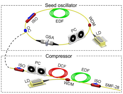
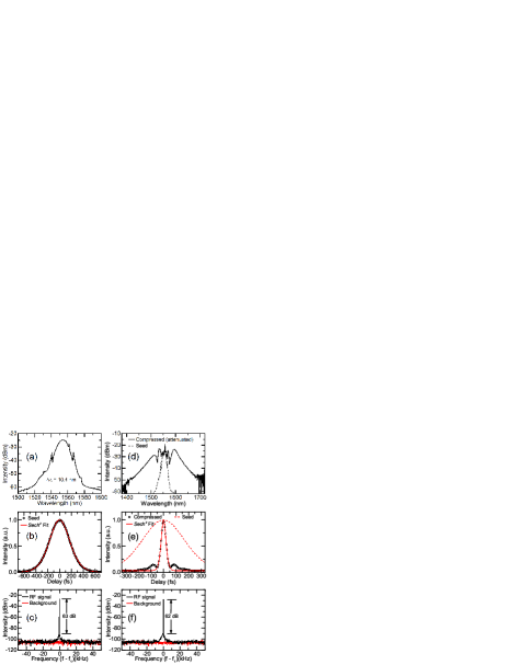
For our seed oscillator, we design a dispersion-managed solitonPopa10apl , able to generate shorter with broader than soliton lasersNelson97apb , schematically presented in Fig.2(a). The total cavity length is 11m. We use a 3.7m EDF, with as gain medium. The rest of the cavity is formed from two lengths of standard SMF: 6.9m of SMF-28 with , and 40cm of Flexcore-1060 with . This gives a net intracavity second-order dispersion ++ -0.07ps2, typical of dispersion-managed soliton lasersPopa10apl ; Popa12apl . The output of the cavity is the 30% port of a coupler. The GSA is placed after the coupler. Fundamental mode-locking is achieved with an output power =0.68mW and repetition rate =18.67MHz. The seed pulse optical spectrum is shown in Fig.3(a), with 10.4nm. The corresponding intensity autocorrelation trace is shown in Fig.3(b), with =263fs, as determined by fitting a sech2 profile to the pulse, as expected for soliton-like mode-lockingAgrawal_anfo . This gives a time bandwidth product (TBP) =0.34, close to the expected transform-limit 0.315Keller04ultra .
The design of the compressor is based on an EDFA, as shown in Fig.2(b). To protect against back reflectionsBecker99edfa , two isolators are placed at both the input and output, consisting of40 and 50cm of SMF-28. To reduce and avoid temporal pulse-shape distortionsFermann_ul or damage to the compressor componentsFermann_ul , we stretch the pulse using3.6m of dispersion compensated fiber (DCF) with , after the input isolator. After the DCF, a WDM consisting of220cm Flexcore-1060, is used to forward pump3m of EDF with , used as the gain medium. Finally, a length of SMF-28, placed after EDF, forms the dispersive delay line, for which an optimized length125cm (including the50cm output isolator) is used, as determined by monitoring the autocorrelation trace at the compressor output until a minimum in the pulse duration is achieved. A polarization controller (PC) is used to match the polarization state of the incident seed pulses (compression optimization).
The EDFA within the compressor is operated with a pump power 350mW. Fig.3(a) plots the optical spectrum recorded at the output of the compressor. 100nm indicates spectral broadening has occurred. The corresponding intensity autocorrelation trace is shown in Fig.3(b), with a sech2 profile of 29fs, i.e. 6 optical cycles. This gives a compression factor . The radio frequency (RF) spectrum of the pulse train, measured with a photodetector connected to an RF spectrum analyzer, is reported in Figs.3(c,d), before and after compression, respectively. Relative to the seed pulses, the compressed pulses have no degradation in signal-to-noise ratio (SNR), indicating pulse stability is maintained during compressionLinde86apb . After compression, =52mW, corresponding to a pulse energy =2.8nJ and =85kW. An increased pedestal is also observed at the base of the pulse, which can be attributed to uncompressed non-linear chirp added to the pulse through SPMAgrawal_anfo . Compensation of higher order chirp terms would enable further reduction in pulse durationKartner_fc ; Agrawal_anfo , as well as minimization of the pedestal structure at the base of the pulseAgrawal_anfo . This can be achieved through control of the higher order dispersion terms within the dispersive delay line. E.g. to control Agrawal_anfo , prism pairs or chirped mirrorsKartner_fc , or lengths of photonic crystal fibers (PCFs)Russel03sc , could be used. The amount of spectral broadening achievable with our setup, therefore the minimum supported pulse duration, is further limited by the maximum of the laser diode used to pump the EDFA. Use of a higher power diode, or a double pumped configuration, should enable the generation of higher bandwidth pulses, as well as enabling increased output power. Finally, wavelength-engineered dispersion management, e.g. using PCFsRussel03sc , coupled with the broadband nature of grapheneBonaccorso10np , could, in principle, extend our approach to enable short pulses at other wavelengths.
Compared to Ti:Sapphire and OPA designs, capable of producing 2-cycle pulsesBrida10jo ; Kartner_fc , our all-fiber design, exploiting a GSA, represents a simple to assemble all-fiber components, needing no critical alignment. A CNT-based fiber setup capable of 14fs pulses at 1550nm was reported in Ref.Kieu10ptl, . Despite the shorter pulses, Ref.Kieu10ptl, used bulk optics (a prism pair)Kieu10ptl , unlike the alignment-free all-fiber format of our laser. Also, a CNT-based SA limits operation wavelength, compared to our GSA, that can operate at any wavelength.
In conclusion, we reported a graphene-mode locked laser generating 29fs pulses with an average output power52mW and pulse energy 2.8nJ, corresponding to a peak power85kW, making it attractive for applications such as optical frequency comb generation and high resolution laser spectroscopy.
We acknowledge funding from EU Graphene Flagship (no. 604391), ERC Grant Hetero2D, EPSRC Grants EP/K01711X/1, EP/K017144/1, EP/M507799/1, EP/L016087/1, a Royal Society Wolfson Research Merit Award and Emmanuel College, Cambridge.
References
- (1) M. E. Fermann, A. Galvanauskas, and G. Sucha, Ultrafast lasers: technology and applications (CRC Press, 2003).
- (2) F. X. Kärtner, Few-Cycle Laser Pulse Generation and Its Applications (Springer, 2004).
- (3) U. Keller, Nature 424, 831 (2003).
- (4) R. Ell, U. Morgner, F. X. Kartner, J. G. Fujimoto, E. P. Ippen, V. Scheuer, G. Angelow, T. Tschudi, M. J. Lederer, A. Boiko, and B. Luther-Davies, Opt. Lett. 26, 373 (2001).
- (5) http://www.coherent.com/download/6416/Chameleon-Ultra-Family-Data-Sheet.pdf
- (6) R. W. Boyd, Nonlinear Optics, (Academic Press, ed. 3nd, 2008).
- (7) R. L. Sutherland, D. G. McLean, and S. Kirkpatrick, Handbook of nonlinear optics (Marcel Dekker, New York, 2003).
- (8) G. Cerullo, and S. De Silvestri, Rev. Sci. Instrum. 74, 1 (2003).
- (9) D. Brida, C. Manzoni, G. Cirmi, M. Marangoni, S. Bonora, P. Villoresi, S. D. Silvestri, G. Cerullo, J. Opt. 12, 013001 (2010).
- (10) M. E. Fermann, and I. Hartl, Nat. Photonics 7, 868 (2013).
- (11) F. Dausinger, F. Lichtner, and H. Lubatschowski, Top. Appl. Phys. 96, 326 (2004).
- (12) M. J. F. Digonnet, Rare earth doped fiber lasers and amplifiers, (Marcel Dekker, NY, USA, 1993).
- (13) P. Russell, Science 299, 358 (2003).
- (14) J. M. Dudley, J. R. Taylor, Nat. Photonics 3, 85 (2009).
- (15) T. Hasan, Z. Sun, F. Wang, F. Bonaccorso, P. H. Tan, A. G. Rozhin, and A. C. Ferrari, Adv. Mater. 21, 3874 (2009).
- (16) Z.Sun,T.Hasan,F.Torrisi,D.Popa,G.Privitera,F.Wang,F. Bonaccorso,D.M.Basko,A.C. Ferrari, ACS Nano, 4, 803 (2010).
- (17) F. Wang, A. G. Rozhin, V. Scardaci, Z. Sun, F. Hennrich, I. H. White, W. I. Milne, and A. C. Ferrari, Nat. Nano. 3, 738 (2008).
- (18) V. Scardaci, Z. P. Sun, F. Wang, A. G. Rozhin, T. Hasan, F. Hennrich, I. H. White, W. I. Milne, and A. C. Ferrari, Adv. Mater. 20, 4040 (2008).
- (19) D. Popa, Z. Sun, T. Hasan, W. Cho, F.Wang, F. Torrisi, and A. Ferrari, Appl. Phys. Lett. 101, 153107 (2012).
- (20) R. Going, D. Popa, F. Torrisi, Z. Sun, T. Hasan, F. Wang, and A. C. Ferrari, Physica E, 44, 1078 (2012).
- (21) C. E. S. Castellani, E. J. R. Kelleher, D. Popa, T. Hasan, Z. Sun, A. C. Ferrari, S. V. Popov, J. R. Taylor, Laser Phys. Lett. 10, 015101 (2013).
- (22) M. Zhang et al. Opt. Express 21, 23261 (2013).
- (23) R. I. Woodward, E. J. R. Kelleher, D. Popa, T. Hasan, F. Bonaccorso, A. C. Ferrari, S. V. Popov, and J. R. Taylor, IEEE Photonic Tech. L. 26, 1672 (2014).
- (24) D. Popa, Z. Sun, T. Hasan, F. Torrisi, F. Wang, and A. C. Ferrari, Appl. Phys. Lett. 98, 073106 (2011).
- (25) Z. Sun, D. Popa, T. Hasan, F. Torrisi, F. Wang, E. J. R. Kelleher, J. C. Travers,V.Nicolosi,A.C. Ferrari, Nano Res. 3, 653 (2010).
- (26) D. Popa, Z. Sun, F. Torrisi, T. Hasan, F. Wang, and A. C. Ferrari, Appl. Phys. Lett. 97, 203106 (2010).
- (27) F. Bonaccorso, Z. Sun, T. Hasan, and A. C. Ferrari, Nat. Photonics 4, 611 (2010).
- (28) D. Brida, A. Tomadin, C. Manzoni, Y. J. Kim, A. Lombardo, S. Milana, R. R. Nair, K. S. Novoselov, A. C. Ferrari, G. Cerullo, M. Polini, Nature Commun. 4, 1987 (2013).
- (29) A. C. Ferrari et al. Nanoscale 7, 4598 (2015).
- (30) F. Bonaccorso, A. Lombardo, T. Hasan, Z. P. Sun, L. Colombo, and A. C. Ferrari, Materials Today, 15, 564 (2012).
- (31) I. H. Baek, H. W. Lee, S. Bae, B. H. Hong, Y. H. Ahn, D.-I. Yeom and F. Rotermund, Appl. Phys. Express 5, 032701 (2012).
- (32) C. A. Zaugg, Z. Sun, V. J. Wittwer, D. Popa, S. Milana, T. S. Kulmala, R. S. Sundaram, M. Mangold, O. D. Sieber, M. Golling, Y. Lee, J. H. Ahn, A. C. Ferrari, and U. Keller, Opt. Express 21, 31548 (2013).
- (33) R. Mary, S. J. Beecher, G. Brown, F. Torrisi, S. Milana, D.Popa, T. Hasan, Z. Sun, E. Lidorikis, S. Ohara, A. C. Ferrari, and A. K. Kar, Opt. Express 21, 7943 (2013).
- (34) M. Zhang, E. J. R. Kelleher, F. Torrisi, Z. Sun, T. Hasan, D. Popa, F. Wang, A. C. Ferrari, S. V. Popov, and J. R. Taylor, Opt. Express. 20 25077 (2012).
- (35) M. N. Cizmeciyan, J. W. Kim, S. Bae, B. H. Hong, F. Rotermund and A. Sennaroglu, Opt. Lett. 38, 341 (2013).
- (36) G. P. Agrawal, Applications of Nonlinear Fiber Optics (Academic Press, London, (2001).
- (37) J. R. Buckley,S.W.Clark,F.W. Wise, Opt. Lett. 31, 1340 (2006).
- (38) X. Zhou, D. Yoshitomi, Y. Kobayashi, and K. Torizuka, Opt. Express 16, 7055 (2008).
- (39) D. Ma, Y. Cai, C. Zhou, W. Zong, L. Chen, and Z. Zhang, Opt. Lett. 35, 2858 (2010).
- (40) K. Tamura, E. P. Ippen, H. A. Haus, and L. E. Nelson, Opt. Lett. 18, 1080 (1993)
- (41) L. E. Nelson, D. J. Jones, K. Tamura, H. A. Haus, and E. P. Ippen, Appl. Phys. B 65, 277 (1997).
- (42) M. J. F. Digonnet, Rare earth doped fiber lasers and amplifiers (Marcel Dekker, NY, USA, 1993).
- (43) V. G. Kravets, A. N. Grigorenko, R. R. Nair, P. Blake, S. Anissimova,K.S.Novoselov,A.K.Geim, Phys. Rev. B 81, 155413 (2010).
- (44) M. Born and E. Wolf, Principles of optics: electromagnetic theory of propagation, interference and diffraction of light, (Cambridge University Press, Cambridge; New York, 1999).
- (45) N. P. Cheremisinoff, Handbook of engineering polymeric materials (Marcel Dekker, New York, 1997).
- (46) A. C. Ferrari, J. C. Meyer, V. Scardaci, C. Casiraghi, M. Lazzeri, F. Mauri, S. Piscanec, D. Jiang, K. S. Novoselov, S. Roth, and A. K. Geim, Phys. Rev. Lett., 97, 187401 (2006).
- (47) A. C. Ferrari, and J. Robertson Phys. Rev.B 61, 14095 (2000).
- (48) F. Torrisi, T. Hasan, W. Wu, Z. Sun, A. Lombardo, T. S. Kulmala, G.-W. Hsieh, S. Jung, F. Bonaccorso, P. J. Paul, D. Chu, and A. C. Ferrari, ACS Nano 6, 2992 (2012).
- (49) C. Casiraghi, A. Hartschuh, H. Qian, S. Piscanec, C. Georgi, A. Fasoli, K. S. Novoselov, D. M. Basko, and A. C. Ferrari, Nano Lett, 9, 1433 (2009).
- (50) A. C. Ferrari, and J. Robertson, Phys. Rev. B 64, 075414 (2001).
- (51) L. G. Cancado, A. Jorio, E. H. M. Ferreira, F. Stavale, C. A. Achete, R. Capaz, M. Moutinho, A. Lombardo, T. S. Kulmala, and A. C. Ferrari, Nano Lett.11, 3190 (2011).
- (52) S. Latil,V.Meunier,L.Henrard, Phys. Rev. B 76, 201402 (2007).
- (53) R. R. Nair, P. Blake, A. N. Grigorenko, K. S. Novoselov, T. J. Booth, T. Stauber, N. M. R. Peres, A. K. Geim, Science 320, 1308 (2008).
- (54) U. Keller, in Progress in Optics 46, 1 (Elsevier, 2004).
- (55) M. Becker, A. Olsson, J. Simpson, Erbium-doped fiber amplifiers: fundamentals and technology (Academic Press, (1999).
- (56) D. v. d. Linde, Appl. Phys. B: Lasers Opt. 39, 201 (1986).
- (57) K. Kieu, R. J. Jones, and N. Peyghambarian, IEEE Photon. Technol. Lett. 22, 1521 (2010).