Error Compensation of Single-Qubit Gates in a Surface Electrode Ion Trap Using Composite Pulses
Abstract
The fidelity of laser-driven quantum logic operations on trapped ion qubits tend to be lower than microwave-driven logic operations due to the difficulty of stabilizing the driving fields at the ion location. Through stabilization of the driving optical fields and use of composite pulse sequences, we demonstrate high fidelity single-qubit gates for the hyperfine qubit of a ion trapped in a microfabricated surface electrode ion trap. Gate error is characterized using a randomized benchmarking protocol, and an average error per randomized Clifford group gate of is measured. We also report experimental realization of palindromic pulse sequences that scale efficiently in sequence length.
pacs:
03.67.-a, 03.67.AcThe trapped atomic ion qubits feature desirable properties for use in a quantum computer such as long coherence times Langer et al. (2005), high fidelity qubit measurement Noek et al. (2013), and universal logic gates Home et al. (2009). The quality of quantum logic gate operations on trapped ion qubits has been limited by the stability of the control fields at the ion location used to implement the gate operations. For this reason, the logic gates utilizing microwave fields Brown et al. (2011); Shappert et al. (2013); Harty et al. (2014) have shown gate fidelities several orders of magnitude better than those using laser fields Knill et al. (2008); Benhelm et al. (2008); Ballance et al. (2014). The UV laser beams used to drive Raman gates for a hyperfine ion qubit present a major challenge as they are subject to severe wavefront distortion in air due to turbulence, leading to amplitude and phase fluctuations at the ion location.
Microfabricated surface electrode ion traps, where atomic ions are trapped above a two dimensional surface of electrodes, can provide a scalable platform on which to build an ion-based quantum computer Chiaverini et al. (2005); Kim et al. (2005). Experiments using surface traps have demonstrated coherence times of more than 1 second Mount et al. (2013), state detection with fidelities greater than 99.9% Noek et al. (2013), and low error single-qubit gates () using integrated microwave waveguides Brown et al. (2011); Harty et al. (2014). Use of high power UV lasers close to the trap surface can lead to substantial charging due to unwanted exposure Harlander et al. (2010). The recent development of single-mode fibers capable of delivering high power UV laser beams Colombe et al. (2014) opens the possibility of significantly reducing the free-space UV beam path length and delivering a clean spatial mode to the ions, eliminating unwanted scattering off nearby trap structures.
Here, we demonstrate low-error single-qubit gates performed using stimulated Raman transitions on an ion qubit trapped in a microfabricated chip trap. Gate errors are measured using a randomized benchmarking protocol Knill et al. (2008); Wallman and Flammia (2014); Magesan et al. (2012), where amplitude error in the control beam is compensated using various pulse sequence techniques Wimperis (1994); Low et al. (2014). Using B2 compensation Wimperis (1994), we demonstrate single-qubit gates with an average error per randomized Clifford group gate of . We also show that compact palindromic pulse compensation sequences (PDn) Low et al. (2014) compensate for amplitude errors as designed.
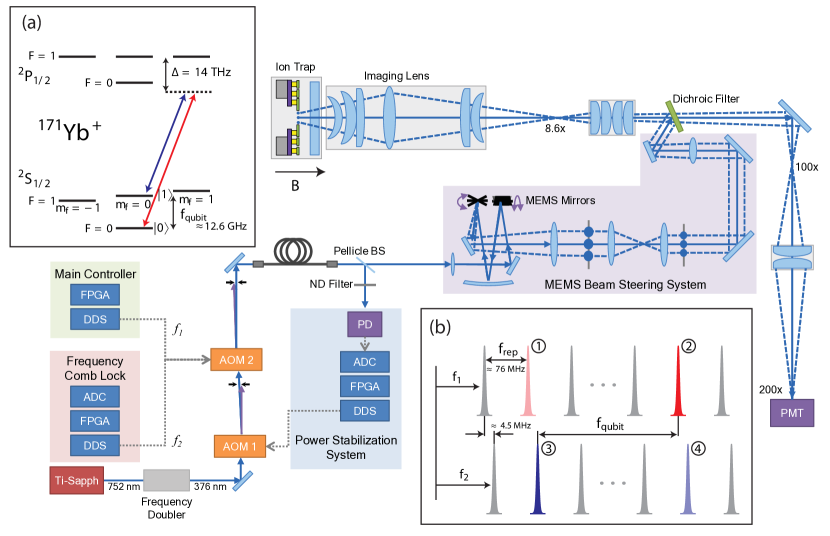
Two hyperfine ground states of the ion (S and S, shown in Fig. 1a, separated by GHz, serve as our qubit states. The energy separation between these states is relatively insensitive to the magnetic field fluctuations at the relevant magnetic field ( kHz/Gauss at 5 Gauss). Continuous wave (CW) lasers are used to perform Doppler cooling, resonant scattering for qubit state detection, and optical pumping out of the state (not pictured in Fig. 1a). For Raman transitions, we use picosecond pulses from a mode-locked titanium-sapphire (Ti:Sapph) laser frequency-doubled to a center wavelength of 376 nm, which creates combs in the frequency domain with comb teeth spacing equal to the laser repetition rate ( MHz). The frequency doubler output is split into two nearly co-propagating frequency combs using a single acousto-optic modulator (AOM2) driven with modulation frequencies and , as shown in the inset Fig. 1b. Resonant transitions are driven by pairs of optical frequency comb teeth (\protect\raisebox{-0.7pt}{\small{2}}⃝ and \protect\raisebox{-0.7pt}{\small{3}}⃝ in Fig. 1b), one from each comb, with a frequency difference equal to Mount et al. (2013); Hayes et al. (2010). As the repetition rate of the laser drifts, the frequency difference between these two comb teeth is actively stabilized to match by adjusting the modulation frequency to maintain the quantity constant Mount et al. (2015); Islam et al. (2014). After the AOMs, the Raman beams are delivered through a 3-m single-mode fiber to a micro-electromechanical systems (MEMS)-based laser beam steering system that is capable of fast (s), re-configurable addressing of individual ions in a linear chain with low crosstalk () Crain et al. (2014). The Raman laser power delivered to the MEMS system is actively stabilized using a gated digital proportional-integral (PI) loop (see below) Mount et al. (2015). After the addressing system, the co-propagating linear polarization of the Raman beams is converted to circular polarization with a quarter-wave plate to drive a -transition. A dichroic filter, which reflects 376 nm light and transmits 370 nm light, is used to fold the Raman beams into a high numerical aperture (NA , PhotonGear) lens that serves the dual purpose of imaging the ion fluorescence and focusing the frequency combs onto the ion. For state detection, the ion is imaged at 200 magnification onto a photomultiplier tube (PMT) array. All experimental timing and measurement recording is carried out by a field-programmable gate array (FPGA) located in our main controller (shown in Fig. 1).
For each experiment, the ion is first Doppler cooled for 1 ms using light that is red-detuned from resonance. The qubit is then initialized to the state by applying CW light resonant with transition for 20 s. Following initialization, the intensity-stabilized Raman beams are pulsed on and off using the AOMs for a duration corresponding to the gate implementation. To measure the qubit state, light resonant with transition is turned on for 400 s while ion fluorescence is measured using the relevant pixel of the PMT array. The ion will fluoresce if the qubit is in the state, while the state remains dark.
Raman beam intensity fluctuations at the ion location result in systematic amplitude errors which decrease gate fidelity. To minimize intensity fluctuations at the ion, a power stabilization system is implemented Mount et al. (2015), where a small amount of collimated light is picked-off after the beam exits the fiber and is incident on a photodiode (PD). The PD provides the error signal for a proportional-integral (PI) feedback loop that controls the amplitude of the direct digital synthesizer (DDS) signal driving AOM 1, as shown in Fig. 1. The PI loop is gated by a digital trigger pulse sent from the FPGA in our main controller. The Raman beams and PI loop are turned on during the Doppler cooling cycle, allowing the power to be stabilized. The loop is then turned off for the remainder of the experiment. Using this approach, the intensity fluctuations due to beam pointing instability before the fiber are corrected. Beam pointing instability after the fiber, due to air currents, is passively suppressed by enclosing the entire experiment in a box.
A composite pulse sequence can be used in place of a single Raman pulse to make it robust against systematic errors such as amplitude, timing, crosstalk, or detuning errors Wimperis (1994); Low et al. (2014); Merrill and Brown (2014); Soare et al. (2014); Merrill et al. (2014) and time-dependent control errors Kabytayev et al. (2014). In our experiment, the impact of residual systematic amplitude errors in the Raman beams is suppressed through the use of compensating pulse sequences. Since these techniques are usually designed to work on systematic errors that are constant over the duration of the sequence, the sequence length determines the bandwidth below which the effect of fluctuating error is suppressed citeKabytayev2014. The length of most compensating pulse sequences increases rapidly at higher error correction order. The palindromic pulse sequences (PDn) are unique in that they scale linearly with the corrected error order (to ) Low et al. (2014). Here we analyze the use of B2 Wimperis (1994) and PD6 Low et al. (2014) composite pulses and their ability to correct static amplitude errors in the presence of additional phase and timing errors for Clifford group gates.
In the absence of noise, the target rotation rotates the Bloch vector by angle around the axis , represented by a unitary propagator . The B2 compensation sequence (also known as BB1), introduced by Wimperis Wimperis (1994), is designed to correct the errors in the pulse area (due to amplitude or timing errors) to , where is the fractional error in the control signal Merrill and Brown (2014). B2 compensation translates each single rotation into a sequence of 4 rotations. A target rotation becomes
| (1) |
where
| (2) |
A single B2 compensated pulse requires a total rotation angle of , which requires time , where is the Rabi frequency. While the B2 sequence is fairly short at , the Bn sequences increase in length exponentially with increasing n, requiring pulses to reduce amplitude errors to Brown et al. (2004).
In comparison to Bn sequences, palindromic compensation sequences (PDn) scale efficiently in length, requiring only pulses () to cancel errors to order, up to Low et al. (2014). Here we use PD6 (), where a target rotation is replaced by
| (3) |
with given for all ’s for and in Table 1.
The direct impact of Raman laser intensity fluctuation is to modify the amplitude of the qubit rotation, which is calibrated prior to each data set by fitting 3-5 periods of Rabi flopping. Raman laser intensity fluctuations also produce detuning errors due to a differential Stark shift between the two qubit levels. To limit the differential AC Stark shift, the power in each Raman beam is made roughly equivalent on the photodiode (PD in Fig. 1) by changing the amplitude of and to ensure equal fiber coupling of both Raman beams. The hyperfine frequency, modified by the differential Stark shift, is found using a Ramsey interference experiment. We begin by initializing the qubit to the state. The qubit is then placed into a superposition state using a microwave Ramsey pulse. This is followed by a wait time of up to 20 ms, during which Raman beams, 1.5 MHz off-resonant from the qubit frequency, are turned on allowing the differential Stark shift to modify the qubit frequency. Then the qubit is rotated again with a second microwave Ramsey pulse. The final state of the ion will oscillate with the wait time when the microwave is off-resonant from the qubit frequency. The exact hyperfine qubit frequency in the presence of the Raman beams is found by scanning the microwave frequency to where the ion state is rotated completely to at all wait times. This microwave frequency is used to compute the driving frequency for AOM 2. Although we carefully calibrate the differential Stark shift, drifts in the individual Raman beam amplitudes cause small changes in the qubit frequency ( Hz), which is not effectively compensated by the pulse sequences used in our experiments.
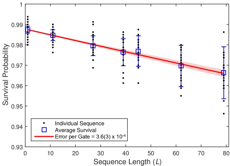
In a randomized benchmarking experiment, the qubit is first initialized to the state, followed by a sequence of gate operations, chosen uniformly and randomly from the 24 Clifford gates (shown in Table 1). A final Clifford gate is then chosen to bring the resulting qubit state to either the or state, at random. Then, the qubit state is measured and compared to the expected state. For each sequence length , 20 random sequences were created and each sequence was measured 800 times, and the fraction of events where the measured result matched the expected result was recorded as the survival probability.
The averaged survival probability per gate length is fit to the zero-order decay model Magesan et al. (2012)
| (4) |
where is the survival probability at length , is related to the average error per Clifford gate (average error = ), and and contain the state preparation and measurement (SPAM) errors and the error on the final rotation.
The error on our measurement was calculated to account for both the variance due to the projective measurement statistics and the variance arising from the spread in fidelities of the underlying distribution of gate sequences, as outlined in Wallman and Flammia (2014). An initial, unweighted, non-linear least squares fit with estimated SPAM errors ( and ) was used to gain a first estimate of the underlying error, and from this an upper bound on the variance is calculated. This estimated variance is used to weight a second non-linear least-squares fit with floating SPAM parameters, and the resulting co-variance matrix was used to calculate the uncertainty. Figure 2 shows the result of a randomized benchmarking experiment for a single-qubit gate using the B2 compensating pulse sequence. Black dots represent the average survival probability of each random sequence measured. The average survival probability of all randomized sequences for each sequence length (blue squares), with an upper-bound variance calculated as in Ref. Wallman and Flammia (2014), are fit to equation (4) (red line) to extract an average error per Clifford group gate of . The error on the fit (light red) accounts for the distribution of measurements and the number of sequences measured for each Wallman and Flammia (2014).
While we expect the actual detuning of the resonant combs arising from the change in the differential AC Stark shift due to amplitude drifts of the Raman beams to be small ( Hz), a much larger effective detuning error exists. The co-propagating Raman beams are circularly polarized, thus, other pairs of comb teeth (\protect\raisebox{-0.7pt}{\small{1}}⃝-\protect\raisebox{-0.7pt}{\small{2}}⃝ pair, \protect\raisebox{-0.7pt}{\small{3}}⃝-\protect\raisebox{-0.7pt}{\small{4}}⃝ pair, and \protect\raisebox{-0.7pt}{\small{1}}⃝-\protect\raisebox{-0.7pt}{\small{4}}⃝ pair in Fig. 1b) can also induce Raman transitions, detuned by MHz (for the case of \protect\raisebox{-0.7pt}{\small{1}}⃝-\protect\raisebox{-0.7pt}{\small{2}}⃝ pair, and \protect\raisebox{-0.7pt}{\small{3}}⃝-\protect\raisebox{-0.7pt}{\small{4}}⃝ pair) and 9 MHz (for the case of \protect\raisebox{-0.7pt}{\small{1}}⃝-\protect\raisebox{-0.7pt}{\small{4}}⃝ pair) in our setup. Further off-resonant beat-notes are also present, but have small contribution to gate errors. The contribution of these off-resonant Raman transitions add additional rotation to the desired state evolution, which is calculated by considering additional terms in the interaction Hamiltonian that describes the qubit subject to the driving field
| (5) | |||||
where the rotations caused by the detuned Raman transitions due to the \protect\raisebox{-0.7pt}{\small{1}}⃝-\protect\raisebox{-0.7pt}{\small{2}}⃝ and \protect\raisebox{-0.7pt}{\small{3}}⃝-\protect\raisebox{-0.7pt}{\small{4}}⃝ pair act coherently on the qubit, and and describe the relative phases between the detuned Raman transitions and the resonant transition, which fluctuate with drifts in the repetition rate of the laser. The unitary propagator that describes time evolution of the qubit subject to this time-dependent interaction Hamiltonian can be computed using the standard Magnus expansion technique Magnus (1954). We use the second-order Magnus expansion to compute the time evolution operator for the qubit subject to each optical pulse. Once the fast oscillating terms (at 4.5MHz and 9MHz) are averaged out, the net impact of the off-resonant terms result in an effective time evolution operator , where represents a deviation of the qubit rotation axis from the plane.
For comparison with the experimental data, we simulated the exact benchmarking sequences used in the experiments in the presence of these imperfections. To simulate each sequence of gates, we calculate the imperfect propagator that describes the state evolution of each pulse, where represents the rotation angle and represents the phase of the driving pulse. Increase in pulse area due to static amplitude noise or timing error in the Raman beams leads to an error in the rotation angle of , where the multiplicative parameter is the same for each pulse in a composite pulse sequence. The presence of off-resonant Raman beams and the (smaller) effect of the differential AC Stark shift are captured in the qubit detuning error . To simulate a wider range of errors in the pulse area, we purposefully change the timing of the pulses yielding the propagator
| (6) |
Our calculation shows that is effectively a random variable in the range of 0-3 kHz due to the drift in the repetition rate of the laser. We calculate a single propagator for each randomized benchmarking sequence by matrix multiplication of the imperfect propagators representing each individual pulse. The resulting final propagators are used to compute the final Bloch state, which is then compared to the expected state yielding a simulated survival probability. The simulated survival probability is fit to equation (4) to produce an average error per gate for each series of sequences given specific noise parameters, which is then compared with the experimental results.
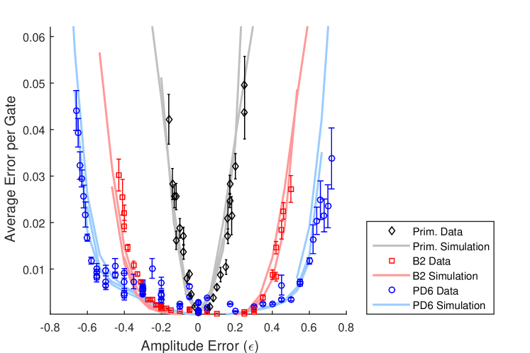
Figure 3 shows a comparison of the error from uncompensated (primitive) gates and gates compensated using B2 and PD6 pulse sequences as a function of timing error. The B2 sequences can keep the gate errors to below 1% for timing error values in the range of , while the PD6 sequences can maintain similar gate error levels for timing error values of up to . Our simulations quantitatively reproduce the range over which the timing errors are compensated for both B2 and PD6 sequences using the imperfect propagator computed from the interaction Hamiltonian given in equation (5). The minimum error value per gate is achieved by B2 sequence in our setup, since the longer sequence length of PD6 makes it more susceptible to the additional errors contributed by off-resonant Raman transitions.
By driving the gates using two beams with polarizations that are orthogonal to each other and the quantization axis, the intra-comb contributions for the off-resonant Raman transitions (pairs \protect\raisebox{-0.7pt}{\small{1}}⃝-\protect\raisebox{-0.7pt}{\small{2}}⃝ and \protect\raisebox{-0.7pt}{\small{3}}⃝-\protect\raisebox{-0.7pt}{\small{4}}⃝) can be eliminated. The remaining leading-order error will come from inter-comb beat notes (pair \protect\raisebox{-0.7pt}{\small{1}}⃝-\protect\raisebox{-0.7pt}{\small{4}}⃝) that can be further detuned by adequate choice of the repetition rate of the mode-locked laser. Our simulations suggest that these modifications can reduce the average error in the single-qubit gates by over one order of magnitude, at which point the gate performance will be limited by other detuning errors (such as the differential AC Stark shift due to amplitude drifts).
In this work, we report high fidelity single-qubit gates driven with tightly focused laser beams on trapped ion qubits by laser intensity stabilization and use of compensating pulse sequences. An error probability as low as is demonstrated unp , consistent with error levels required for realizing a range of quantum error-correction schemes Fowler et al. (2012); Steane (2003); Raussendorf and Harrington (2007). We experimentally verified the value of novel, length-efficient pulse sequences (PDn) that suppress errors to higher orders with modest sequence lengths.
The authors would like to acknowledge helpful discussions with True Merrill and Jonathan Mizrahi. This work was supported by the Office of the Director of National Intelligence and Intelligence Advanced Research Projects Activity through the Army Research Office, the ARC via EQuS project number CE11001013, and by the US Army Research Office grant numbers W911NF-14-1-0098 and W911NF-14-1-0103. STF also acknowledges support from an ARC Future Fellowship FT130101744.
| 0.38266 | -2.51430 | -1.75192 | 0.05941 | 2.67572 | 0.39344 | |
| 0.34769 | -3.06979 | 1.55852 | -0.70890 | 3.09692 | -0.62174 |
| Clifford gate | Physical gates | Clifford gate | Physical gates |
|---|---|---|---|
| 1 | I | 13 | Z/2 & X |
| 2 | X | 14 | X & Z/2 |
| 3 | Y | 15 | Z/2 & X/2 |
| 4 | Z | 16 | Y/2 & Z/2 |
| 5 | X/2 | 17 | X/2 & -Z/2 |
| 6 | Y/2 | 18 | Y/2 & Z |
| 7 | Z/2 | 19 | -X/2 & Z/2 |
| 8 | -X/2 | 20 | -Z/2 & Y/2 |
| 9 | -Y/2 | 21 | Z & Y/2 |
| 10 | -Z/2 | 22 | -Z/2 & X/2 |
| 11 | Z & X/2 | 23 | X/2 & Z/2 |
| 12 | X/2 & Z | 24 | -Y/2 & -Z/2 |
References
- Langer et al. (2005) C. Langer, R. Ozeri, J. D. Jost, J. Chiaverini, B. DeMarco, A. Ben-Kish, R. B. Blakestad, J. Britton, D. B. Hume, W. M. Itano, et al., Physical Review Letters 95, 4 (2005).
- Noek et al. (2013) R. Noek, G. Vrijsen, D. Gaultney, E. Mount, T. Kim, P. Maunz, and J. Kim, Optics Letters 38, 4735 (2013).
- Home et al. (2009) J. P. Home, D. Hanneke, J. D. Jost, J. M. Amini, D. Leibfried, and D. J. Wineland, Science 325, 1227 (2009).
- Brown et al. (2011) K. R. Brown, A. C. Wilson, Y. Colombe, C. Ospelkaus, A. M. Meier, E. Knill, D. Leibfried, and D. J. Wineland, Physical Review A 84, 030303 (2011).
- Shappert et al. (2013) C. M. Shappert, J. T. Merrill, K. Brown, J. M. Amini, C. Volin, S. C. Doret, H. Hayden, C. Pai, and A. Harter, New Journal of Physics 15, 083053 (2013).
- Harty et al. (2014) T. Harty, D. Allcock, C. Ballance, L. Guidoni, H. Janacek, N. Linke, D. Stacey, and D. Lucas, Physical review letters 113, 220501 (2014).
- Knill et al. (2008) E. Knill, D. Leibfried, R. Reichle, J. Britton, R. B. Blakestad, J. D. Jost, C. Langer, R. Ozeri, S. Seidelin, and D. J. Wineland, Physical Review A 77, 012307 (2008).
- Benhelm et al. (2008) J. Benhelm, G. Kirchmair, C. F. Roos, and R. Blatt, Nature Physics 4, 463 (2008).
- Ballance et al. (2014) C. Ballance, T. Harty, N. Linke, and D. Lucas, arXiv preprint arXiv:1406.5473 (2014).
- Chiaverini et al. (2005) J. Chiaverini, R. B. Blakestad, J. Britton, J. D. Jost, C. Langer, D. Leibfried, R. Ozeri, and D. J. Wineland, Quantum Information and Computation 5, 419 (2005).
- Kim et al. (2005) J. Kim, S. Pau, Z. Ma, H. R. McLellan, J. V. Gates, A. Kornblit, R. E. Slusher, R. M. Jopson, I. Kang, and M. Dinu, Quantum Information and Computation 5, 515 (2005).
- Mount et al. (2013) E. Mount, S.-Y. Baek, M. Blain, D. Stick, D. Gaultney, S. Crain, R. Noek, T. Kim, P. Maunz, and J. Kim, New Journal of Physics 15, 093018 (2013).
- Harlander et al. (2010) M. Harlander, M. Brownnutt, W. Hänsel, and R. Blatt, New Journal of Physics 12, 093035 (2010).
- Colombe et al. (2014) Y. Colombe, D. H. Slichter, A. C. Wilson, D. Leibfried, and D. J. Wineland, Optics express 22, 19783 (2014).
- Wallman and Flammia (2014) J. J. Wallman and S. T. Flammia, New Journal of Physics 16, 103032 (2014).
- Magesan et al. (2012) E. Magesan, J. M. Gambetta, and J. Emerson, Physical Review A 85, 042311 (2012).
- Wimperis (1994) S. Wimperis, Journal of Magnetic Resonance, Series A 109, 221 (1994).
- Low et al. (2014) G. H. Low, T. J. Yoder, and I. L. Chuang, Physical Review A 89, 022341 (2014).
- Hayes et al. (2010) D. Hayes, D. N. Matsukevich, P. Maunz, D. Hucul, Q. Quraishi, S. Olmschenk, W. Campbell, J. Mizrahi, C. Senko, and C. Monroe, Physical Review Letters 104 (2010).
- Mount et al. (2015) E. Mount, D. Gaultney, G. Vrijsen, M. Adams, S. Baek, K. Hudek, L. Isabella, S. Crain, A. van Rynbach, P. Maunz, et al., arXiv:1504.00035 (2015).
- Islam et al. (2014) R. Islam, W. Campbell, T. Choi, S. Clark, C. Conover, S. Debnath, E. Edwards, B. Fields, D. Hayes, D. Hucul, et al., Optics Letters 39, 3238 (2014).
- Crain et al. (2014) S. Crain, E. Mount, S. Baek, and J. Kim, Applied Physics Letters 105, 181115 (2014).
- Merrill and Brown (2014) J. T. Merrill and K. R. Brown, Quantum Information and Computation for Chemistry: Advances in Chemical Physics Volume 154 pp. 241–294 (2014).
- Soare et al. (2014) A. Soare, H. Ball, D. Hayes, J. Sastrawan, M. C. Jarratt, J. J. McLoughlin, X. Zhen, T. J. Green, and M. J. Biercuk, Nature Physics 10, 825 (2014).
- Merrill et al. (2014) J. T. Merrill, S. C. Doret, G. Vittorini, J. Addison, and K. R. Brown, Physical Review A 90, 040301 (2014).
- Kabytayev et al. (2014) C. Kabytayev, T. J. Green, K. Khodjasteh, M. J. Biercuk, L. Viola, and K. R. Brown, Physical Review A 90, 012316 (2014).
- Brown et al. (2004) K. R. Brown, A. W. Harrow, and I. L. Chuang, Physical Review A 70, 052318 (2004).
- Magnus (1954) W. Magnus, Communications on Pure and Applied Mathematics 7, 649 (1954).
- (29) Similar high fidelity single qubit Raman gates have been demonstrated receintly in unpublished work by the NIST Ion Storage Group (Boulder, CO) and D. Lucas et al. (University of Oxford).
- Fowler et al. (2012) A. G. Fowler, M. Mariantoni, J. M. Martinis, and A. N. Cleland, Physical Review A 86, 032324 (2012).
- Steane (2003) A. Steane, Physical Review A 68, 042322 (2003).
- Raussendorf and Harrington (2007) R. Raussendorf and J. Harrington, Physical Review Letters 98, 190504 (2007).