Binary phase oscillation of two mutually coupled semiconductor lasers
Shoko Utsunomiya1, Naoto Namekata2, Kenta Takata1,3, Daisuke Akamatsu4, Shuichiro Inoue2, and Yoshihisa Yamamoto1,4,5
1. National Institute of Informatics, Hitotsubashi 2-1-2, Chiyoda-ku, Tokyo 101-8403, Japan , 2. Nihon University, 1-8-14 Kanda-Surugadai, Chiyoda-ku, Tokyo, 101-8308, Japan 3. Department of Information and Communication Engineering, The University of Tokyo, Tokyo 113-8654, Japan, 4. National Metrology Institute of Japan(NMIJ), National Institute of Advanced Industrial Science and Technology(AIST), Central 3, 1-1-1 Umezono, Tsukuba, Ibaraki 305-8563 Japan, 5. E. L. Ginzton Laboratory, Stanford University, Stanford, California 94305, USA
shoko@nii.ac.jp
Abstract
A two-site Ising model is implemented as an injection-locked laser network consisting of a single master laser and two mutually coupled slave lasers. We observed ferromagnetic and antiferromagnetic orders in the in-phase and out-of-phase couplings between the two slave lasers. Their phase difference is locked to either 0 or even if the coupling path is continuously modulated. The system automatically selects the oscillation frequency to satisfy the in-phase or out-of-phase coupling condition, when the mutual coupling dominates over the injection-locking by the master laser.
OCIS codes: (030.0030) Coherence and statistical optics, (140.3520) Lasers, injection-locked, (270.5585) Quantum information and processing.
References and links
- [1] F. Barahona, ”On the computational complexity of Ising spin glass models,” J. Phys. A: Math. Gen. 15, 3241-3253 (1982).
- [2] H. Nishimori, ”Statistical Physics of Spin Glasses and Information Processing: An Introduction”, (Oxford University Press, New York, 2001).
- [3] E. Farhi, J. Goldstone, S. Gutmann, J. Lapan, A. Lundgren and D. Preda, ”A Quantum Adiabatic Evolution Algorithm Applied to Random Instances of an NP-Complete Problem,” Science. 292, no. 5516 pp. 472-475 (2001).
- [4] A. P. Young, S. Knysh and V. N. Smelyanskiy, ”First-order phase transition in the quantum adiabatic algorithm,” Phys. Rev. Lett. 104, 020502 (2010)
- [5] S. Boixo, T. F. Ronnow, S. V. Isakov, Z. Wang, D. Wecker, D. A. Lidar, J. M. Martinis and M. Troyer, ”Quantum annealing with more than one hundred qubits,” Phys. Rev. A 88, 063853 (2013)
- [6] R. Feynman, ”Simulating physics with computers,” Int. J. Theor. Phys. 21, 467-488 (1982).
- [7] A. Friedenauer, H. Schmitz, J. T. Glueckert, D. Porras, and T. Schaetz, ”Simulating a quantum magnet with trapped ions,” Nature Physics, 4, 757 (2008).
- [8] K. Kim, M.-S. Chang, S. Korenblit, R. Islam, E. E. Edwards, J. K. Freericks, G.-D. Lin, L.-M. Duan, and C. Monroe, ”Quantum simulation of frustrated Ising spins with trapped ions,” Nature 465, 590 (2010).
- [9] E. E. Edwards, S. Korenblit, K. Kim, R. Islam, M.-S. Chang, J. K. Freericks, G.-D. Lin, L.-M. Duan, and C. Monroe, ”Quantum simulation and phase diagram of the transverse-field Ising model with three atomic spins,” Phys. Rev. B 82, 060412 (2010).
- [10] R. Islam, E.E. Edwards, K. Kim, S. Korenblit, C. Noh, H. Carmichael, G.-D. Lin, L.-M. Duan, C.-C. Joseph Wang, J.K. Freericks and C. Monroe, ”Onset of a quantum phase transition with a trapped ion quantum simulator,” Nature Communications 2, 77 (2011)
- [11] S. Utsunomiya, K. Takata and Y. Yamamoto, ”Mapping of Ising models onto injection-locked laser systems,” Optics Express 19, Issue 19, pp. 18091-18108 (2011)
- [12] K. Takata, S. Utsunomiya and Y. Yamamoto, ”Transient time of an Ising machine based on injection-locked laser network,” New J. Phys. 14 013052 (2012).
- [13] Z. Wang, A. Marandi, K. Wen, R. L. Byer, and Y. Yamamoto, ”A Coherent Ising Machine Based On Degenerate Optical Parametric Oscillators,” Phys. Rev. A 88, 063853 (2013)
- [14] A. Marandi,, Z. Wang,, K. Takata,, R. L. Byer and Y. Yamamoto, ”Network of time-multiplexed optical parametric oscillators as a coherent Ising machine, ” Nature Photonics, doi:10.1038/nphoton.2014.249, (2014)
- [15] P. Ray, B. K. Chakrabarti, and A. Chakrabarti, ”Sherrington-Kirkpatrick model in a transverse field: Absence of replica symmetry breaking due to quantum fluctuations,” Stocastic Proc. Appl. 33, 233 (1989)
- [16] S. Kobayashi and T. Kimura, ”Injection Locking in AIGaAs Semiconductor Laser,” IEEE J. Quantum Electron. 17, 5, 689 (1981)
- [17] L. Gillner, G. Bjork and Y. Yamamoto, ”Quantum noise properties of an injection-locked laser oscillator with pump-noise suppression and squeezed injection,” Phys. Rev A41, 9, 5053 (1990)
- [18] S. Saito, O. Nilsson, Y. Yamamoto, ”Oscillation center frequency tuning, quantum FM noise, and direct frequency characteristics in external grating loaded semiconductor lasers” , IEEE Journal of Quantum Electronics 18, 6 (1982)
- [19] F. Rogister and M. Blondel, ”Dynamics of two mutually delayed-coupled semiconductor lasers,” Optics Communications 239, 173-180 (2004)
- [20] H. Fujino, J. Ohtsubo, ”Synchronization of Chaotic Oscillations in Mutually Coupled Semiconductor Lasers,” Optical Review 8, Issue 5, pp 351-357 (2001)
1 Introduction
Combinational optimization problems are ubiquitous in our modern life. Classic examples include protein folding in life-science and medicine, frequency assignment in wireless communications, navigation and routing, microprocessor circuit design, computer vision and voice recognition in machine learning and control in social network. Those combinatorial optimization problems often belong to NP (Non-deterministic Polynomial-time) hard problems, for which modern digital computers and future quantum computers cannot find exact solutions in polynomial time.
Three-dimensional Ising models and two-dimensional Ising models with a Zeeman term are also known to be NP complete/hard problems[1]. Quantum annealing has been proposed to solve such Ising models by utilizing quantum mechanical tunneling induced by a transverse field [2]- [4]. This concept was implemented with superconducting flux qubits in the D-Wave One / Two machines [5]. The idea of quantum simulation is to use a well-controlled quantum system to simulate the behavior of another quantum system [6]. Recent experiments using trapped ions [7]-[10] have realized quantum simulation of Ising models.
We have proposed an alternative scheme for implementing such Ising models with
an injection-locked laser network [11, 12].
Another physical implementation of Ising model based on degenerate optical
parametric oscillators is also proposed [13] where the binary Ising spins are represented by the
bistable phase (0 or ) of a degenerate optical parametric oscillator (DOPO) and experimentally demonstrated [14] with DOPO pulses. In principle, such injection-locked laser network and
parametric oscillation network can be operated at room temperature and constructed
as relatively compact systems. The Ising spins in the laser network studied in the
present work are represented by the discrete phases ( or )
of single-mode slave lasers with respect to the master laser phase rather than
two orthogonal polarization modes proposed in the original paper [11].
Here, we describe the first experimental implementation of a two-site Ising
machine using an injection-locked laser network.
2 Ising spins in injection-locked slave lasers
Our goal is to implement the Ising models with a Zeeman term in an injection-locked laser network. The Ising Hamiltonian with a Zeeman term is described as
| (1) |
In this Hamiltonian, describes an Ising spin, i.e., spin projection onto the z-axis. is the interaction coefficient between spin and spin , and is a supplemental Zeeman (external field) term. In contrast to the standard Ising model with nearest neighbour coupling, here we deal with an arbitrary graph in which a vertex can be connected to any other vertices. The injection-locked laser network proposed in our previous paper [11, 12] can find the ground state of the Hamiltonian, Eq. , through a laser phase transition. A photon in the lasing mode is not localized in any specific slave laser but its wavefunction is coherently spread over all slave lasers as partial waves of each individual photon. At the end of the computation, the phase configuration of such partial waves is expected to represent the spin configuration of a particular ground state .
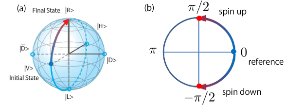
Ising spins are represented by the polarization states of the slave lasers as
shown in Fig. 1(a), where and represent right
circular (up-spin) and left circular (down-spin) polarizations, respectively.
Each slave laser is injection locked by a master laser and prepared in the
vertical polarized state . Then, the polarization state evolves
towards either the right or left circular polarization after the mutual couplings
between the slave lasers are turned on. Such polarization evolutions are described
as a change in the relative phase between the equal amplitude diagonal polarization
states and (see Fig. 1(a)). The
amplitudes of two diagonal polarizations and are held
constant but their phase difference continuously evolves during the computation.
This phase-based picture, immediately makes it apparent that we need only one
polarization state because the phase of the another polarization state
is inversely-symmetric to the phase of state.
In the new model, the Ising spins are represented by the phase of
the single slave laser mode, as shown in Fig. 1(b). The zero phase, as
the reference, is determined by the phase of the injected master laser. When the
master laser injection is reasonably strong and the self-oscillation frequency of
the slave laser is identical to that of the master laser, the phase of the slave
laser is identical to that of the master laser, i.e. . The phase
rotates to from the initial phase due to the
mutual coupling between the slave lasers , which corresponds to the Ising spin
rotating to the up or down state.
3 Experimental setup
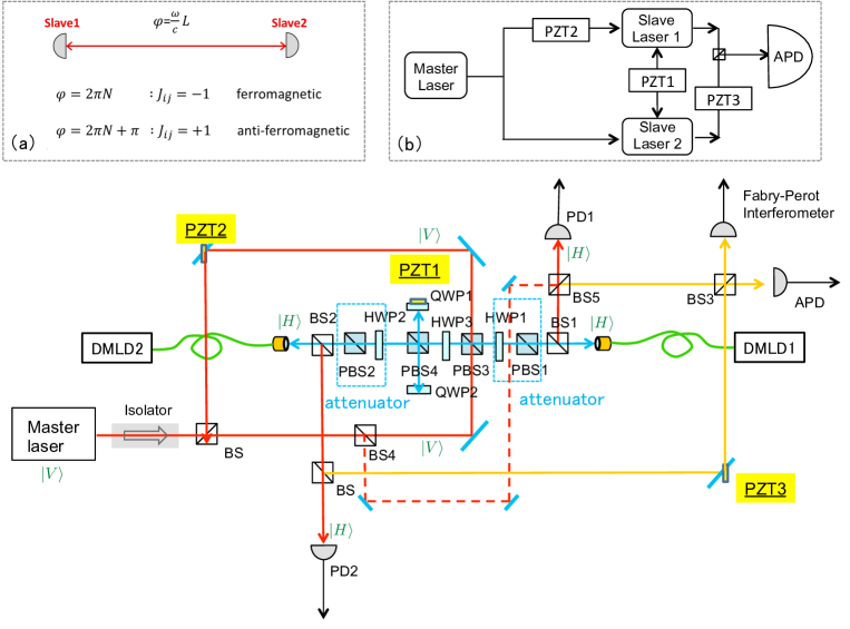
In our experimental setup, a master laser signal is uni-directionally injected into two slave lasers, which also implements the Zeeman term in Eq. (1) if the phase is slightly rotated towards either or from the standard phase zero. The slave lasers are mutually coupled by bi-directional injection-locking, which implements of the Ising coupling term in Eq. (1). The detailed experimental setup is depicted in Fig. 2. The optical path length between the two slave lasers and those between each slave and master laser are independently controlled by a polarization-dependent optical path. We used a tunable external cavity single-mode diode laser as the master laser(Koshin Kogaku LS-601A-56S2); it oscillates around 1577.5 nm with a spectral linewidth kHz. We used discrete mode diode lasers (DMLD, Eblana photonics FLDs) with a spectral linewidth kHz as the slave lasers.
Two slave lasers are mutually coupled along the blue line in Fig. 2. These slave lasers are nearly identical, and their injection currents are set to be the same in the experiment. However, their temperatures must be tuned so as to make their self-oscillation frequencies identical. The optical path length between the slave lasers is mm. Moreover, their optical path length is controlled by piezoelectric transducer 1 (PZT1), wherein the modulation voltage is used to shift the position of the reflection mirror with a quarter wave plate 1 (QWP1). The role of the quarter wave plate 1 inserted before PZT1 is to transform the vertical polarization light from the slave laser 1 to the horizontal polarization light before transmitting through PBS4. Likewise, the quarter wave plate 2 transforms the incident horizontal polarization light to the vertical polarization light before reflecting from PBS4. The same transformation is performed onto the output light from the slave laser 2. The two slave lasers oscillate in the horizontal polarization. The polarization beam splitter 1 (PBS1) and half wave plate 1 (HWP1) work together as attenuators for the beam from one slave laser (DMLD2), while PBS2 and HWP2 attenuate the light from the other slave laser (DMLD1). HWP3 is set at to the polarization axis so that the polarization of the incident beam from the slave laser 1 (DMLD1) into HWP3 is rotated to the horizontal polarization and it is reflected to QWP1 by PBS4. The master laser signal is injected into both slave lasers. The master laser oscillates in the vertical polarization and is converted into the horizontal polarization when it goes through HWP3. The optical path length for the master laser signal is not influenced by PZT1. The phase of the master laser signal injected into slave laser 1 which comes from the upper branch of the red line is modulated by the mirror mounted on PZT2. The output beams from the slave laser 1 and slave laser 2 are partially reflected at BS1 and BS2 and combined at BS3 along the yellow line. The PZT3 modulates only optical path length from the slave laser to the BS3 without toughing the optical path length from the slave laser 1 to BS3, so that the interference pattern between the two slave laser outputs can be obtained at APD. The spectral linewidth and the interferometer output between the two slave lasers are detected with a scanning Fabry-Perot interferometer (FPI) and an InGaAs/InP avalanche photo diode (APD). As shown in inset(a) of Fig.2 , the ferromagnetic and the anti-ferromagnetic couplings are implemented by in-phase and out-of phase coupling path length between the two slave lasers.The inset(b) of Fig.2 shows a simplified picture of the experimental setup in Fig.2. A master laser signal is injected to the two slave lasers and a path from the master laser to the slave laser 1 is modulated by PZT2. The mutual coupling path between the two slave lasers is modulated by PZT1. A path difference in the interference between the two slave lasers is modulated by PZT3.
4 Slave laser phase modulation by injection-locking
The phase of the injection-locked slave laser is continuously shifted from that of the master laser if there is a frequency detuning between the master laser and slave laser within the locking bandwidth [12]. The phase of an injection-locked slave laser shifts continuously from to inside the locking bandwidth. Denoting the frequency detuning between the slave laser and the master laser by , the relative phase shift satisfies the following relation:
| (2) | |||||
| (3) |
where is the self-oscillation frequency of the slave laser without injection-locking and is the master laser oscillation frequency, and are, respectively, the injection field amplitude from the master laser and slave laser internal field amplitude, and is an external cavity quality factor of the slave laser. is the linewidth enhancement factor. is normalized to express a photon flux, while is normalized to represent a photon number.
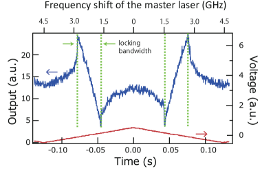
We measured the phase shift of the slave laser due to the frequency detuning
between the master laser and the slave laser within
the locking bandwidth. The frequency of the master laser is externally modulated
at a 10-Hz repetition rate through its injection current. In Fig. 3
the red line shows the applied voltage used to modulate the injection current.
The blue line shows the interference signal between slave laser 1 and the master
laser observed at BS5 in Fig. 2 for identical output powers of mW.
The range of the frequency excursion of the master laser is GHz to cover the
full locking bandwidth. The observed locking bandwidth is GHz (the
locking-bandwidth boundaries are indicated by the green dotted lines). Since the
slave laser has a negligible linewidth enhancement factor, ,
the locking bandwidth is given by
[16, 17] where
and are the input and output
powers of the slave laser. However, in the slave laser (DMLD) used in this experiment, most
of its cavity is formed by a passive waveguide without carriers so that the
effective linewidth enhancement factor is negligible. This is experimentally
manifested by the symmetric phase excursion of the slave laser for upward and
downward frequency detuning shown in Fig. 3.
The phase of the slave laser is supposed to shift from
to with the frequency detuning between the
master and slave lasers [17].
The relative phase shift shown in Fig. 3 is monotonical with the frequency
detuning, which indicates the linewidth enhancement factor of the slave
laser (DMLD) is indeed small.
5 Numerical simulation for two mutually coupled slave lasers
In the phase model of an injection-locked laser network, the binary phase of each slave laser acts as an Ising spin [11]. The c-number Langevin equations of the time-dependent amplitude , phase , and carrier number for an i-th slave laser are described as,
| (4) | |||||
| (5) | |||||
| (6) |
Here , and are the Langevin noise terms for the amplitude, phase and carrier number. is the cavity photon decay rate, is the optical attenuation coefficient of the master laser injection signal, is the common attenuation coefficient of the Zeeman term and Ising term, is the spontaneous emission lifetime, is the pump rate into the slave laser i , is the spontaneous emission rate for i-th slave laser. is the fractional coupling efficiency of spontaneous emission into a lasing mode [11].
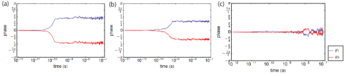
Figure 4 shows numerical simulation results for the time-dependent phases of the two slave lasers, where the Ising coupling is (anti-ferromagnetic coupling). In this case, the steady state solution is an anti-ferromagnetic order, which means the two slave lasers have opposite phases. In the numerical simulation, the slave laser phases are initially set to the reference phase (zero), which is determined by the master laser injection signal. When the mutual coupling term is switched on, as shown in Fig. 4(a), the slave laser phases bifurcate into and . On the other hand, when the injection from the master laser is relatively strong compared to the mutual coupling, as shown in Fig. 4(c), the slave laser phases stay in the reference phase (zero). When the mutual coupling between two slave lasers is slightly decreased, the relative phase difference between them is smaller than as shown in Fig. 4(b). It is assumed that the frequency of the two slave lasers are locked to the master laser frequency in these numerical simulations.
6 Switching between ferromagnetic and anti-ferromagnetic phase orders
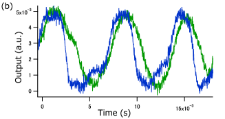
We experimentally studied how the slave laser phases are modulated when the optical path length between the two slave lasers (DMLDs) is varied. Notice that the optical path length modulates the polarity of the Ising coupling term . We observed a transition from one regime, where the Ising coupling is dominant, to the other regime, where the master injection term is dominant, when we changed the ratio of the uni-directional injection from the master laser into the two slave lasers to the mutual coupling between the two slave lasers by rotating HWP1 or HWP2 in Fig. 2. Figure 5 (a) shows the interference signal between the two slave lasers (DMLD1 and 2) when there is relatively strong mutual coupling between them, with and W. Here is the injection power from the master laser into a fiber coupler of the slave laser 1 and is the injection power from the slave laser 2 into the fiber coupler of the slave laser 1. It is observed that the strongly coupled slave lasers prefer to oscillate in discrete phases. The relative phase difference between two slave lasers seems to be either 0 or , as demonstrated by an interference signal in Fig. 5(a). The frequencies of the two slave lasers now deviate from that of the master laser, as described in the next section. We observed that the slave lasers still oscillate at identical frequencies, which is true even after the injection master signal is turned off. The voltage applied to PZT1 linearly increases as a function of time in Fig. 5. The PZT1 displacement is / =12.23 m/V with respect to the applied voltage . The optical path modulation for mutual coupling causes the phase difference between the two slave lasers to have discrete jumps every V. The high and low outputs correspond to the ferromagnetic and anti-ferromagnetic phase orders. When the master laser injection and the mutual coupling signals are set to be and , the interference signal doesn’t show any modulation against the mutual coupling path modulation (Fig. 5(c)). When the two signal intensities, are set to be on the same order (W) as shown in Fig. 5(b), the interference signal shows a transition between the mutual coupling dominant regime in Fig. 5(a) and the master injection dominant regime in Fig. 5(c).
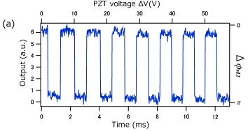
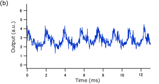
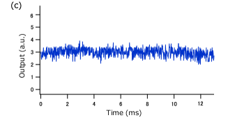
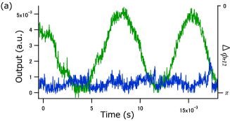
Figure 6 shows the interference output when the two slave laser signals
are combined at BS3 and detected by the APD as shown in Fig. 2.
The blue line shows the interference signal when PZT2 is electrically driven
linearly as a function of time, which causes the phase of the master laser
signal injected into the slave laser 1 (DMLD1) to be modulated. The blue trace in
Fig. 6(a) shows the case of using the same experimental parameters
of W and W as Fig. 5(a),
where the mutual coupling is stronger than the uni-directional master signal
injection. Here, the phase modulation of the injected master laser signal is not
effective. The green trace in Fig.6(a) shows the interference signal when
only PZT3 is linearly modulated as a function of time, which manifests the phase
coherence between the two slave lasers. The blue trace in Fig. 6(b)
shows the interference signal with PZT2 modulation under a relatively strong master
signal injection (W) compared with the mutual injection power
(W). Here, the interference signal has the same phase
modulation of the master laser. It suggests that the oscillating phase of slave
lasers are mainly determined by the injected master laser signal and
there’s phase coherence between two slave lasers as
shown by the green trace in Fig. 6(b).
7 Spontaneous frequency selection of mutually coupled slave lasers
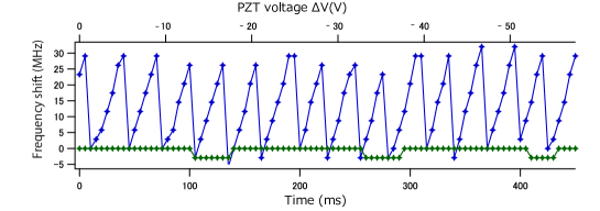
We observed a sawtooth variation in the slave laser frequency when the optical path length between the slave lasers is modulated, as shown by blue dots in Fig. 7. Here the mutual coupling is dominant over the master laser injection. The experimental results shown in Fig. 6(a) indicate that the oscillation frequencies of the two slave lasers are synchronized in the strong mutual coupling regime. We measured the frequency shift of the slave laser 1 (DMLD1) with the FPI at the top right corner in Fig. 2 , while the signal from the slave laser 2 (DMLD2) is blocked just before BS3. Figure 7 plots the slave laser frequency shift against the mutual coupling path length modulation between the two slave lasers. When the mutual coupling is stronger than the master laser signal injection, a sawtooth frequency shift of MHz is observed as shown by the blue line in Fig. 7. In this case, the phases are pinned either in the same phase or in the opposite phase, as shown in Fig. 5(a). On the other hand, the oscillation frequency of the slave laser is held constant, when the master laser injection is dominant, as shown by the green line in Fig. 7. Here discrete jumps in the oscillation frequency are experimental artifacts due to the discretization error(resolution limit) of the FPI. There are sawtooth-frequency-shift cycles when the applied voltage is swept over V, so that frequency shift occurs at every applied voltage of V, which corresponds to a PZT1 shift of nm. This sawtooth-frequency-shift is considered to be the result of spontaneous selection of the synchronized oscillation frequencies of the two slave lasers to minimize the overall threshold pump current or to maximize the output power [18]. The favorable phase difference between the two slave lasers is either or so that the two slave lasers build up a standing wave between the edges of the two slave lasers.
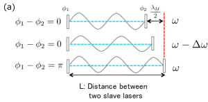
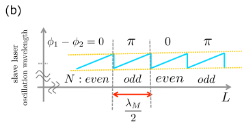
Figure 8 is a schematic explanation of the spontaneous frequency optimization. When the optical path length between the two slave lasers is an integer multiple of the self-oscillation wavelength , the number of loops of the standing wave is even, so that the two slave lasers oscillate with the same phase. In the second figure of Fig. 8(a), the oscillation wavelength become slightly elongated as the optical path length is extended while the phase difference between the two slave lasers is still . However, when is shifted from the resonant condition in the first figure of Fig. 8(a), the oscillation frequency returns to the self-oscillation frequency and the number of the loops of the standing wave between the two facets is odd, so that the phase difference between the two slave lasers is . We plot that description of oscillation frequency shift as a function of in Fig. 8(b). is the number of the loops and corresponding phase differences , are written at the top. The light blue line shows the slave laser oscillation frequency shift according to the linear shift of . This frequency shift for a path length variation corresponds to the free spectral range at the optical cavity length .
The path length variation for a single frequency shift event in our experiment as shown in Fig. 5 is because the path length between the two slave lasers changes twice when the position of the mirror just before QWP is changed. The expected position shift of PZT1 for a single sawtooth frequency shift is nm which is close to the measured position shift of PZT1 nm. The optical path length between the two slave lasers in Fig. 2 is mm. The sawtooth modulation in Fig. 7 is MHz, which is less than 30 percent of the estimated frequency shift MHz. The difference between the experimentally observed frequency excursion and the free spectral range stems from the phase shifts associated with the reflection from the two slave laser facets. As indicated in Eq. (3), the slave laser phase shifts away from the injection signal phase when there is a detuning between the self-oscillation frequency and the actual oscillation frequency .
8 Conclusion
We have implemented a two-site Ising model by using the two mutually coupled slave lasers that are simultaneously injection-locked by a single master laser. As shown in Fig. 5(a), the two slave lasers feature the ferromagnetic and anti-ferromagnetic orders when the two lasers are coupled in-phase () or out-of-phase (), which is the ground state of the Ising Hamiltonian. The transition from the Ising-term dominant regime to the master-injection-term dominant regime was observed. The phase of the slave laser is continuously synchronized with that of a master laser when the master laser injection is stronger than the mutual coupling between the slave lasers. On the other hand, when the mutual coupling is stronger than the master laser injection, the phases of the two slave lasers jump discretely and the oscillation frequencies continuously shift with the optical path length modulation between the two slave lasers. In that case, the mutually coupled slave lasers communicate with each other and oscillate at the optimum frequency, where a standing wave develops between them that results in either a ferromagnetic or anti-ferromagnetic phase order. We note that as related work, the dynamic and chaotic oscillation behaviors of mutually coupled semiconductor lasers have been studied numerically and experimentally [19][20].
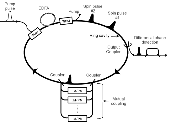
For practical implementation of a larger-scale laser network based Ising machine, we can use a higher harmonic fiber mode-locked laser as shown in Fig. 9. In this implementation, optical pulses are simultaneously produced in a single fiber ring cavity so that they have identical oscillation frequencies. In order to implement the Ising coupling term, , we can introduce optical delay lines with independent intensity and phase modulators. The pick-off signal from i-th pulse is properly modulated in its intensity and phase, and coupled to the j-th pulse with an appropriate delay time. This time division multiplexing scheme allows us to implement mutual coupling paths by only delay lines. Finally, the computational results are recorded by the one-bit delay differential phase detection [14].
When implementing with a higher harmonic mode-locked fiber laser with 1GHz repetition frequency and 20m fiber ring cavity,
the total number of optical pulses is 100 in this system.
If we increase the clock frequency up to 10GHz and the fiber length up to 200m, we can implement 10,000 optical pulses.
9 Acknowledgments
The authors would like to thank S. Tamate for fruitful discussions. This research is supported by the Cabinet Office, Government of Japan and the Japan Society for the Promotion of Science (JSPS) through the Funding Program for World-Leading Innovative R&D on Science and Technology (FIRST Program) and a Matsuo academic grant and Shiseido Female Researcher Science Grant.
This paper was published in Optics Express and is made available as an electronic reprint with the permission of OSA. The paper can be found at the following URL on the OSA website: http://www.opticsinfobase.org/oe/abstract.cfm?uri=oe-23-5-6029 . Systematic or multiple reproduction or distribution to multiple locations via electronic or other means is prohibited and is subject to penalties under law.