Theory of Quantum Imaging with Undetected Photons

Mayukh Lahiri mayukh.lahiri@univie.ac.at Vienna Center for Quantum Science and Technology (VCQ), Faculty of Physics, Boltzmanngasse 5, University of Vienna, Vienna A-1090, Austria.    Radek Lapkiewicz Vienna Center for Quantum Science and Technology (VCQ), Faculty of Physics, Boltzmanngasse 5, University of Vienna, Vienna A-1090, Austria.    Gabriela Barreto Lemos Vienna Center for Quantum Science and Technology (VCQ), Faculty of Physics, Boltzmanngasse 5, University of Vienna, Vienna A-1090, Austria.    Anton Zeilinger Vienna Center for Quantum Science and Technology (VCQ), Faculty of Physics, Boltzmanngasse 5, University of Vienna, Vienna A-1090, Austria. Institute for Quantum Optics and Quantum Information, Austrian Academy of Sciences, Boltzmanngasse 3, Vienna A-1090, Austria.
Abstract

Abstract: A novel quantum imaging technique has recently been demonstrated in an experiment, where the photon used for illuminating an object is not detected; the image is obtained by interfering two beams, none of which ever interacts with the object. Here we present a detailed theoretical analysis of the experiment. We show that the object information is present only in the interference term and not in the individual intensities of the interfering beams. We also theoretically establish that the magnification of the imaging system depends on two wavelengths: the average wavelength of the photon that illuminates the object and the average wavelength of the photon that is detected. Our analysis affirms that the imaging process is based on the principle that quantum interference occurs when interferometric path information is unavailable.

I Introduction

According to Bohr, comprehending the nature of a quantum system requires “a combined use of the contrasting pictures” of a classical particle and a classical wave Bohr-Einstein . Bohr’s complementarity principle Bohr-comp implies that the complete particle behavior and the complete wave behavior of a quantum system or entity are mutually exclusive. In other words, if a quantum entity behaves completely like a particle (wave) under certain experimental conditions, it does not display its wave (particle) behavior under the same conditions. To avoid confusion, we do not refer to a quantum entity as either “particle” or “wave”; instead, we use the term “quanton” (see, for example, quanton-ref ).

The wave-particle duality can be illustrated by a lowest-order Note-order-interf interference experiment (e.g., Young’s double-slit experiment, Mach-Zehnder interferometer, etc.), in which a single quanton (e.g., photon, electron, etc.) is sent into a two-way interferometer (see, for example, Feynman-lec-3 ). If the quanton behaves completely like a particle, no interference can be observed at the output of the interferometer. It turns out that in this case it is possible to determine with complete certainty via which path the quanton has traversed. On the other hand, when there is absolutely no information on the path traveled by the quanton, perfect interference occurs—a behavior that characterizes waves. The relationship between interference and path information (wave-particle duality) has drawn the attention of several researchers (see, for example, GY-neutron-interf ; M-ind ; JSV ; Eng-WPI ; ANVKZZ-C60 ).

The imaging process LBCRLZ-mandel-im of our interest is related to the wave-particle duality of photons. Let us consider two spatially separated identical light sources, 1 and 2, each of which has the ability of producing two photons at a time. These two photons are, in general, not identical with each other and we label them by a𝑎a and b𝑏b. Suppose now that we select the a𝑎a-photons from the both sources and send them into a two-arm interferometer under the following conditions: 1) photons from a particular source can travel through only one of the arms; 2) the sources emit at the same rate but in such a way that there is never more than one photon present in the interferometer at a time. In this case, although the a𝑎a-photons are identical with each other, one can partially or fully extract the interferometric path information by interacting with a b𝑏b-photon that is not sent into the interferometer. In such a situation, it is, therefore, possible to control the interference of a photon sent into the interferometer by using a photon that is not sent into the interferometer. This phenomenon has been experimentally demonstrated and discussed in Refs. ZWM-ind-coh-PRL ; WZM-ind-coh-PRA and is often referred to as “induced coherence without induced emission”.

The essence of our imaging technique LBCRLZ-mandel-im lies in the fact that the effect of interaction with b𝑏b-photons is observed in the first-order interference fringe pattern produced by the a𝑎a-photons. As for sources, we use two identical nonlinear crystals which generate photons by spontaneous parametric down-conversion. In Section II, we briefly recapitulate some basic results relating to the theory of spontaneous parametric down-conversion. In Section III, we then present a detailed analysis of the imaging method. Finally, we summarize our results in Section IV.

II Elements of the Theory of Spontaneous Parametric Down-conversion

We mostly follow the theory of the process of spontaneous parametric down-conversion developed by Hong and Mandel HM-pdc-PRA . In this process a nonlinear crystal converts a photon (pump) into two photons (signal and idler) each of which has energy lower than that of the pump-photon. The combined energy of the signal and the idler photons is equal to the energy of the pump-photon. When the pump beam is highly coherent and the down-conversion does not bring any observable change in the pump intensity, one can represent the pump by a classical electric field 𝐄P(𝐫,t)subscript𝐄𝑃𝐫𝑡\mathbf{E}_{P}(\mathbf{r},t). In this case, the interaction Hamiltonian associated with the process of parametric down-conversion can be expressed in the interaction picture as (cf. WZM-ind-coh-PRA ; HM-pdc-PRA )

H^in(t)subscript^𝐻𝑖𝑛𝑡\displaystyle\widehat{H}_{in}(t)
=Dd3rχ~lmqEPl(𝐫,t)E^Sm()(𝐫,t)E^Iq()(𝐫,t)+H.c.,absentsubscript𝐷superscript𝑑3𝑟subscript~𝜒𝑙𝑚𝑞subscript𝐸𝑃𝑙𝐫𝑡subscriptsuperscript^𝐸𝑆𝑚𝐫𝑡subscriptsuperscript^𝐸𝐼𝑞𝐫𝑡H.c.\displaystyle=\int_{D}d^{3}r~{}\mbox{\Large$\widetilde{\chi}$}_{lmq}E_{Pl}(\mathbf{r},t)\widehat{E}^{(-)}_{Sm}(\mathbf{r},t)\widehat{E}^{(-)}_{Iq}(\mathbf{r},t)+\text{H.c.}~{}, (1)

where 𝝌~~𝝌\widetilde{\boldsymbol{\chi}} represents the nonlinear electric susceptibility tensor of the crystal, 𝐄^S()(𝐫,t)subscriptsuperscript^𝐄𝑆𝐫𝑡\widehat{\mathbf{E}}^{(-)}_{S}(\mathbf{r},t) and 𝐄^I()(𝐫,t)subscriptsuperscript^𝐄𝐼𝐫𝑡\widehat{\mathbf{E}}^{(-)}_{I}(\mathbf{r},t) are the negative frequency parts of the quantized electric fields associated with the signal and idler, respectively, D𝐷D is the volume of the crystal, H.c. implies Hermitian conjugation, and there is summation over the repeated indices l𝑙l, m𝑚m, q𝑞q which label three mutually orthogonal directions in space.

The pump, the signal and the idler fields may oscillate at different optical frequencies. In general, the susceptibility of the crystal depends on these frequencies. The Hamiltonian in Eq. (II) is therefore often expressed by decomposing the optical fields into several modes (see, for example, HM-pdc-PRA ). The positive frequency part of a quantized electric field inside the crystal can be represented by the expression Note-em-quant-NLmed

𝐄^(+)(𝐫,t)superscript^𝐄𝐫𝑡\displaystyle\widehat{\mathbf{E}}^{(+)}{(\mathbf{r},t)} =𝐤,σα(𝐤,σ)exp[i(𝐤𝐫ωt)]𝐞𝐤,σa^(𝐤,σ),absentsubscript𝐤𝜎𝛼𝐤𝜎𝑖𝐤𝐫𝜔𝑡subscript𝐞𝐤𝜎^𝑎𝐤𝜎\displaystyle=\sum_{\mathbf{k},\sigma}\alpha(\mathbf{k},\sigma)\exp\left[i(\mathbf{k}\cdot\mathbf{r}-\omega t)\right]\mathbf{e}_{\mathbf{k},\sigma}~{}\widehat{a}(\mathbf{k},\sigma), (2)

where σ=1,2𝜎12\sigma=1,2, labels two directions of polarization, ω𝜔\omega is the frequency, 𝐤𝐤\mathbf{k} is the wave vector, 𝐞𝐤,σsubscript𝐞𝐤𝜎\mathbf{e}_{\mathbf{k},\sigma} represents two generally complex, mutually orthogonal unit vectors such that 𝐞𝐤,σ𝐤=0subscript𝐞𝐤𝜎𝐤0\mathbf{e}_{\mathbf{k},\sigma}\cdot\mathbf{k}=0, α(𝐤,σ)=iω/(2ϵ0n2(𝐤,σ)L3)𝛼𝐤𝜎𝑖Planck-constant-over-2-pi𝜔2subscriptitalic-ϵ0superscript𝑛2𝐤𝜎superscript𝐿3\alpha(\mathbf{k},\sigma)=i\sqrt{\hbar\omega/(2\epsilon_{0}n^{2}(\mathbf{k},\sigma)L^{3})}, ϵ0subscriptitalic-ϵ0\epsilon_{0} is the electric permittivity of free space, n(𝐤,σ)𝑛𝐤𝜎n(\mathbf{k},\sigma) is the refractive index of the anisotropic, nonlinear crystal, L3superscript𝐿3L^{3} is the quantization volume, and a^(𝐤,σ)^𝑎𝐤𝜎\widehat{a}(\mathbf{k},\sigma) is the photon annihilation operator for the mode labeled by (𝐤,σ)𝐤𝜎(\mathbf{k},\sigma). Let us also decompose the pump field inside the crystal into plane wave modes and express it in the form

𝐄P(𝐫,t)=𝐤P,σPVP(𝐤P,σP)exp[i(𝐤P𝐫ωPt)]𝐞𝐤P,σP.subscript𝐄𝑃𝐫𝑡subscriptsubscript𝐤𝑃subscript𝜎𝑃subscript𝑉𝑃subscript𝐤𝑃subscript𝜎𝑃𝑖subscript𝐤𝑃𝐫subscript𝜔𝑃𝑡subscript𝐞subscript𝐤𝑃subscript𝜎𝑃\displaystyle\mathbf{E}_{P}{(\mathbf{r},t)}=\sum_{\mathbf{k}_{P},\sigma_{P}}V_{P}(\mathbf{k}_{P},\sigma_{P})\exp\left[i(\mathbf{k}_{P}\cdot\mathbf{r}-\omega_{P}t)\right]\mathbf{e}_{\mathbf{k}_{P},\sigma_{P}}. (3)

The Hamiltonian, given by Eq. (II), now takes the form (cf. GHOM-pdc-intf-PRA )

H^in(t)subscript^𝐻𝑖𝑛𝑡\displaystyle\widehat{H}_{in}(t)
=Dd3r𝐤P,σP𝐤S,σS𝐤I,σI{χlmq(ωP,ωS,ωI)VP(𝐤P,σP)\displaystyle=\int_{D}d^{3}r\sum_{\mathbf{k}_{P},\sigma_{P}}\sum_{\mathbf{k}_{S},\sigma_{S}}\sum_{\mathbf{k}_{I},\sigma_{I}}\Big{\{}\mbox{\Large$\chi$}_{lmq}(\omega_{P},\omega_{S},\omega_{I})V_{P}(\mathbf{k}_{P},\sigma_{P})
(𝐞𝐤P,σP)l(𝐞𝐤S,σS)m(𝐞𝐤I,σI)qα(𝐤S,σS)α(𝐤I,σI)subscriptsubscript𝐞subscript𝐤𝑃subscript𝜎𝑃𝑙subscriptsubscriptsuperscript𝐞subscript𝐤𝑆subscript𝜎𝑆𝑚subscriptsubscriptsuperscript𝐞subscript𝐤𝐼subscript𝜎𝐼𝑞superscript𝛼subscript𝐤𝑆subscript𝜎𝑆superscript𝛼subscript𝐤𝐼subscript𝜎𝐼\displaystyle\qquad\left(\mathbf{e}_{\mathbf{k}_{P},\sigma_{P}}\right)_{l}\left(\mathbf{e}^{\ast}_{\mathbf{k}_{S},\sigma_{S}}\right)_{m}\left(\mathbf{e}^{\ast}_{\mathbf{k}_{I},\sigma_{I}}\right)_{q}\alpha^{\ast}(\mathbf{k}_{S},\sigma_{S})\alpha^{\ast}(\mathbf{k}_{I},\sigma_{I})
exp[i(ωS+ωIωP)t]exp[i(𝐤P𝐤S𝐤I)𝐫]𝑖subscript𝜔𝑆subscript𝜔𝐼subscript𝜔𝑃𝑡𝑖subscript𝐤𝑃subscript𝐤𝑆subscript𝐤𝐼𝐫\displaystyle\qquad\exp\left[i(\omega_{S}+\omega_{I}-\omega_{P})t\right]\exp\left[i(\mathbf{k}_{P}-\mathbf{k}_{S}-\mathbf{k}_{I})\cdot\mathbf{r}\right]
a^S(𝐤S,σS)a^I(𝐤I,σI)}+H.c.,\displaystyle\qquad\widehat{a}^{{\dagger}}_{S}(\mathbf{k}_{S},\sigma_{S})~{}\widehat{a}^{{\dagger}}_{I}(\mathbf{k}_{I},\sigma_{I})\Big{\}}\quad+\quad\text{H.c.}~{}, (4)

where the subscripts P𝑃P, S𝑆S and I𝐼I refer to pump, signal and idler, respectively. The quantum state of light generated by down-conversion at the crystal is given by the well known formula

|ψ(t)=exp[1i0t𝑑tH^in(t)]|vac,ket𝜓superscript𝑡1𝑖Planck-constant-over-2-pisuperscriptsubscript0superscript𝑡differential-d𝑡subscript^𝐻𝑖𝑛𝑡ketvac\left|\psi(t^{\prime})\right\rangle=\exp\left[\frac{1}{i\hbar}\int_{0}^{t^{\prime}}dt~{}\widehat{H}_{in}(t)\right]\left|\text{vac}\right\rangle, (5)

where |vacketvac\left|\text{vac}\right\rangle is the vacuum state and tsuperscript𝑡t^{\prime} is the interaction time. By expanding the exponential, Eq. (5) can be expressed in the form

|ψ(t)=|vac+[1i0t𝑑tH^in(t)]|vac+.ket𝜓superscript𝑡ketvacdelimited-[]1𝑖Planck-constant-over-2-pisuperscriptsubscript0superscript𝑡differential-d𝑡subscript^𝐻𝑖𝑛𝑡ketvac\left|\psi(t^{\prime})\right\rangle=\left|\text{vac}\right\rangle+\left[\frac{1}{i\hbar}\int_{0}^{t^{\prime}}dt~{}\widehat{H}_{in}(t)\right]\left|\text{vac}\right\rangle+\dots. (6)

III Imaging

Let us consider a situation in which two identical nonlinear crystals NL1 and NL2 are pumped by optical beams P1subscript𝑃1P_{1} and P2subscript𝑃2P_{2}, respectively, generated by the same laser source (Fig. 1).
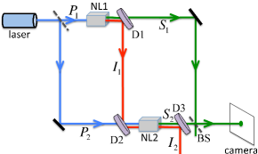
Refer to caption
Figure 1: Illustrating the principle of the experiment. A laser beam (blue) is split into two beams P1subscript𝑃1P_{1} and P2subscript𝑃2P_{2} which pump the nonlinear crystals NL1 and NL2. The crystals produce signal (green) and idler (red) beams. The idler beam I1subscript𝐼1I_{1} is aligned with the idler beam I2subscript𝐼2I_{2}. The signal beams S1subscript𝑆1S_{1} and S2subscript𝑆2S_{2} are superposed by the beam splitter BS and one of the outputs of BS is detected by a camera. D1, D2, D3 are dichroic mirrors.

The idler beam, I1subscript𝐼1I_{1}, generated by NL1 is transmitted through NL2 and is aligned with the idler beam, I2subscript𝐼2I_{2}, generated by the latter. The signal beams S1subscript𝑆1S_{1} and S2subscript𝑆2S_{2} from the crystals NL1 and NL2, respectively, are superposed by a beam-splitter, BS. One of the outputs of the beam-splitter is detected by an EMCCD camera.

Suppose that the pump fields at the two crystals are given by the complex electric field vectors 𝐄P1(𝐫1,t2)subscript𝐄subscript𝑃1subscript𝐫1subscript𝑡2\mathbf{E}_{P_{1}}(\mathbf{r}_{1},t_{2}) and 𝐄P2(𝐫2,t2)subscript𝐄subscript𝑃2subscript𝐫2subscript𝑡2\mathbf{E}_{P_{2}}(\mathbf{r}_{2},t_{2}), expanded in the form given by Eq. (3). From Eqs. (2), (3), (II) and (6) it follows that the quantum state of light generated by each individual crystal is given by the formula (cf. WMPS )

|ψj(t)ketsubscript𝜓𝑗superscript𝑡\displaystyle\left|\psi_{j}(t^{\prime})\right\rangle
=|vac+tDi𝐤Pj,σPj𝐤Sj,σSj𝐤Ij,σIj[χlmq(ωPj;ωSj,ωIj)\displaystyle=\left|\text{vac}\right\rangle+\frac{t^{\prime}D}{i\hbar}\sum_{\mathbf{k}_{P_{j}},\sigma_{P_{j}}}\sum_{\mathbf{k}_{S_{j}},\sigma_{S_{j}}}\sum_{\mathbf{k}_{I_{j}},\sigma_{I_{j}}}\Big{[}\mbox{\Large$\chi$}_{lmq}(\omega_{P_{j}};\omega_{S_{j}},\omega_{I_{j}})
VPj(𝐤Pj,σPj)α(𝐤Sj,σSj)α(𝐤Ij,σIj)(𝐞𝐤Pj,σPj)lsubscript𝑉subscript𝑃𝑗subscript𝐤subscript𝑃𝑗subscript𝜎subscript𝑃𝑗superscript𝛼subscript𝐤subscript𝑆𝑗subscript𝜎subscript𝑆𝑗superscript𝛼subscript𝐤subscript𝐼𝑗subscript𝜎subscript𝐼𝑗subscriptsubscript𝐞subscript𝐤subscript𝑃𝑗subscript𝜎subscript𝑃𝑗𝑙\displaystyle\quad V_{P_{j}}(\mathbf{k}_{P_{j}},\sigma_{P_{j}})~{}\alpha^{\ast}(\mathbf{k}_{S_{j}},\sigma_{S_{j}})\alpha^{\ast}(\mathbf{k}_{I_{j}},\sigma_{I_{j}})\left(\mathbf{e}_{\mathbf{k}_{P_{j}},\sigma_{P_{j}}}\right)_{l}
(𝐞𝐤Sj,σSj)m(𝐞𝐤Ij,σIj)qexp[i(ωSj+ωIjωPj)t/2]subscriptsubscriptsuperscript𝐞subscript𝐤subscript𝑆𝑗subscript𝜎subscript𝑆𝑗𝑚subscriptsubscriptsuperscript𝐞subscript𝐤subscript𝐼𝑗subscript𝜎subscript𝐼𝑗𝑞𝑖subscript𝜔subscript𝑆𝑗subscript𝜔subscript𝐼𝑗subscript𝜔subscript𝑃𝑗superscript𝑡2\displaystyle\quad\left(\mathbf{e}^{\ast}_{\mathbf{k}_{S_{j}},\sigma_{S_{j}}}\right)_{m}\left(\mathbf{e}^{\ast}_{\mathbf{k}_{I_{j}},\sigma_{I_{j}}}\right)_{q}\exp\left[i(\omega_{S_{j}}+\omega_{I_{j}}-\omega_{P_{j}})t^{\prime}/2\right]
sinc[(ωSj+ωIjωPj)t/2]sincdelimited-[]subscript𝜔subscript𝑆𝑗subscript𝜔subscript𝐼𝑗subscript𝜔subscript𝑃𝑗superscript𝑡2\displaystyle\quad\text{sinc}[(\omega_{S_{j}}+\omega_{I_{j}}-\omega_{P_{j}})t^{\prime}/2]
exp[i(𝐤Pj𝐤Sj𝐤Ij)𝐫0j]𝑖subscript𝐤subscript𝑃𝑗subscript𝐤subscript𝑆𝑗subscript𝐤subscript𝐼𝑗subscript𝐫subscript0𝑗\displaystyle\quad\exp\left[i(\mathbf{k}_{P_{j}}-\mathbf{k}_{S_{j}}-\mathbf{k}_{I_{j}})\cdot\mathbf{r}_{0_{j}}\right]
{n=13sinc[(𝐤Pj𝐤Sj𝐤Ij)nln/2]}superscriptsubscriptproduct𝑛13sincdelimited-[]subscriptsubscript𝐤subscript𝑃𝑗subscript𝐤subscript𝑆𝑗subscript𝐤subscript𝐼𝑗𝑛subscript𝑙𝑛2\displaystyle\quad\Big{\{}\prod_{n=1}^{3}\text{sinc}[(\mathbf{k}_{P_{j}}-\mathbf{k}_{S_{j}}-\mathbf{k}_{I_{j}})_{n}l_{n}/2]\Big{\}}
|𝐤Sj,σSjSj|𝐤Ij,σIjIj]+,\displaystyle\quad\left|\mathbf{k}_{S_{j}},\sigma_{S_{j}}\right\rangle_{S_{j}}~{}\left|\mathbf{k}_{I_{j}},\sigma_{I_{j}}\right\rangle_{I_{j}}\Big{]}+\dots, (7)

where j=1,2𝑗12j=1,2 labels the two crystals, |𝐤Sj,σSjSj=a^Sj(𝐤Sj,σSj)|vacSjsubscriptketsubscript𝐤subscript𝑆𝑗subscript𝜎subscript𝑆𝑗subscript𝑆𝑗subscriptsuperscript^𝑎subscript𝑆𝑗subscript𝐤subscript𝑆𝑗subscript𝜎subscript𝑆𝑗subscriptketvacsubscript𝑆𝑗\left|\mathbf{k}_{S_{j}},\sigma_{S_{j}}\right\rangle_{S_{j}}=\widehat{a}^{{\dagger}}_{S_{j}}(\mathbf{k}_{S_{j}},\sigma_{S_{j}})\left|\text{vac}\right\rangle_{S_{j}}, |𝐤Ij,σIjIj=a^Ij(𝐤Ij,σIj)|vacIjsubscriptketsubscript𝐤subscript𝐼𝑗subscript𝜎subscript𝐼𝑗subscript𝐼𝑗subscriptsuperscript^𝑎subscript𝐼𝑗subscript𝐤subscript𝐼𝑗subscript𝜎subscript𝐼𝑗subscriptketvacsubscript𝐼𝑗\left|\mathbf{k}_{I_{j}},\sigma_{I_{j}}\right\rangle_{I_{j}}=\widehat{a}^{{\dagger}}_{I_{j}}(\mathbf{k}_{I_{j}},\sigma_{I_{j}})\left|\text{vac}\right\rangle_{I_{j}}, the volume integration has been carried out assuming the crystal to be a rectangular parallelepiped Note-cryst-vol of sides l1subscript𝑙1l_{1}, l2subscript𝑙2l_{2}, l3subscript𝑙3l_{3} with its center located at the point 𝐫0jsubscript𝐫subscript0𝑗\mathbf{r}_{0_{j}}, and sinc[x]=sinx/xsincdelimited-[]𝑥𝑥𝑥\text{sinc}[x]=\sin x/x; the sinc terms lead to the two well known phase matching conditions associated with the process of spontaneous parametric down-conversion.

III.1 Alignment of Idler Beams

If the beam I1subscript𝐼1I_{1} is perfectly aligned with the beam I2subscript𝐼2I_{2}, for each mode present in the quantized field 𝐄^I1(+)subscriptsuperscript^𝐄subscript𝐼1\widehat{\mathbf{E}}^{(+)}_{I_{1}} of I1subscript𝐼1I_{1} there exists an equally populated mode in the quantized field 𝐄^I2(+)subscriptsuperscript^𝐄subscript𝐼2\widehat{\mathbf{E}}^{(+)}_{I_{2}} of I2subscript𝐼2I_{2}. The perfect alignment of the idler beams can, therefore, be analytically expressed by the following formula:

a^I2(𝐤I,σI)=a^I1(𝐤~I,σ~I)exp[iϕI(𝐤~I,σ~I)],subscript^𝑎subscript𝐼2subscript𝐤𝐼subscript𝜎𝐼subscript^𝑎subscript𝐼1subscript~𝐤𝐼subscript~𝜎𝐼𝑖subscriptitalic-ϕ𝐼subscript~𝐤𝐼subscript~𝜎𝐼\displaystyle\widehat{a}_{I_{2}}(\mathbf{k}_{I},\sigma_{I})=\widehat{a}_{I_{1}}(\widetilde{\mathbf{k}}_{I},\widetilde{\sigma}_{I})~{}\exp[i\phi_{I}(\widetilde{\mathbf{k}}_{I},\widetilde{\sigma}_{I})], (8)

where the mode (𝐤~I,σ~I)subscript~𝐤𝐼subscript~𝜎𝐼(\widetilde{\mathbf{k}}_{I},\widetilde{\sigma}_{I}) is generated at NL1 and is aligned with the mode (𝐤I,σI)subscript𝐤𝐼subscript𝜎𝐼(\mathbf{k}_{I},\sigma_{I}) that is generated at NL2; ϕI(𝐤~I,σ~I)subscriptitalic-ϕ𝐼subscript~𝐤𝐼subscript~𝜎𝐼\phi_{I}(\widetilde{\mathbf{k}}_{I},\widetilde{\sigma}_{I}) is a phase factor which can be interpreted as the phase gained by the mode (𝐤~I,σ~I)subscript~𝐤𝐼subscript~𝜎𝐼(\widetilde{\mathbf{k}}_{I},\widetilde{\sigma}_{I}) due to propagation from NL1 to NL2.

The Hamiltonian given by Eq. (II) and, consequently, the state in Eq. (III) are expressed in quite general forms. We now simplify them using certain assumptions which are appropriate to our experiment. Let us assume that the signal and the idler can be treated as beams with uniform linear polarization both inside and outside of the crystals. In such a situation, we can drop the summation over the polarization indices σPjsubscript𝜎subscript𝑃𝑗\sigma_{P_{j}}, σSjsubscript𝜎subscript𝑆𝑗\sigma_{S_{j}}, σIjsubscript𝜎subscript𝐼𝑗\sigma_{I_{j}} and can also write

α(𝐤Sj,σSj)αS(ωSj),α(𝐤Ij,σIj)αI(ωIj),formulae-sequenceapproximately-equals-or-equals𝛼subscript𝐤subscript𝑆𝑗subscript𝜎subscript𝑆𝑗subscript𝛼𝑆subscript𝜔subscript𝑆𝑗approximately-equals-or-equals𝛼subscript𝐤subscript𝐼𝑗subscript𝜎subscript𝐼𝑗subscript𝛼𝐼subscript𝜔subscript𝐼𝑗\displaystyle\alpha(\mathbf{k}_{S_{j}},\sigma_{S_{j}})\approxeq\alpha_{S}(\omega_{S_{j}}),\qquad\alpha(\mathbf{k}_{I_{j}},\sigma_{I_{j}})\approxeq\alpha_{I}(\omega_{I_{j}}), (9)

One can now replace the annihilation operator a^(𝐤,σ)^𝑎𝐤𝜎\widehat{a}(\mathbf{k},\sigma) with a^(𝐤)^𝑎𝐤\widehat{a}(\mathbf{k}), the number state |𝐤,σket𝐤𝜎\left|\mathbf{k},\sigma\right\rangle with |𝐤ket𝐤\left|\mathbf{k}\right\rangle and the susceptibility tensor χlmqsubscript𝜒𝑙𝑚𝑞\mbox{\Large$\chi$}_{lmq} with a scalar quantity χ𝜒\chi. Furthermore, the alignment condition given by Eq. (8) reduces to the form

a^I2(𝐤I)=a^I1(𝐤~I)exp[iϕI(𝐤~I)].subscript^𝑎subscript𝐼2subscript𝐤𝐼subscript^𝑎subscript𝐼1subscript~𝐤𝐼𝑖subscriptitalic-ϕ𝐼subscript~𝐤𝐼\displaystyle\widehat{a}_{I_{2}}(\mathbf{k}_{I})=\widehat{a}_{I_{1}}(\widetilde{\mathbf{k}}_{I})~{}\exp[i\phi_{I}(\widetilde{\mathbf{k}}_{I})]. (10)

It is to be noted that the relationship between 𝐤~Isubscript~𝐤𝐼\widetilde{\mathbf{k}}_{I} and 𝐤Isubscript𝐤𝐼\mathbf{k}_{I} depends on the optical system used for aligning the idler beams.

Refer to caption
Figure 2: Schematics of the imaging experiment. Positive lenses L1 and L2 (both of focal length fIsubscript𝑓𝐼f_{I}), placed in the path of I1subscript𝐼1I_{1}, form a 4-f system that images NL1 on NL2. An identical 4-f system, consisting of positive lenses L3 and L4, is placed in the path of S1subscript𝑆1S_{1}. A thin object is placed on a plane which is the back focal plane of L1 and the front focal plane of L2. One of the outputs of BS is focused by a positive lens L0 of focal length f0subscript𝑓0f_{0} into a camera. NL2 and the back focal plane, ΓΓ\Gamma, of L4 are located at the front focal plane of L0. The lenses are assumed to be thin and ideal. The superposed signal beam is passed through a narrow-band filter, F, before entering the camera.

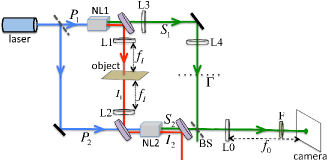
In the experiment the two idler beams are aligned by the use of a 4-f lens system that images a central plane of NL1 onto a central plane of NL2 (Fig. 2). We assume the idler beam axis to be along the optical axis of the lens system. A thin object which is intended to be imaged is placed at the back focal plane of the first positive lens, L1, of the 4-f system; this plane is also the front focal plane of the second positive lens, L2, of the same 4-f system. Clearly, the object is illuminated only by the idler beam that is generated by the first crystal.

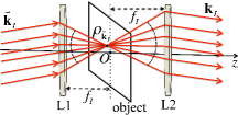
If a plane wave characterized by the wave vector 𝐤~Isubscript~𝐤𝐼\widetilde{\mathbf{k}}_{I} is incident on L1, it gets converted into a spherical wave that converges to a point 𝝆𝐤~Isubscript𝝆subscript~𝐤𝐼\boldsymbol{\rho}_{\widetilde{\mathbf{k}}_{I}}, say, on the back focal plane of L1 [Fig. 3]. It then reemerges from this point as a diverging spherical wave. The amplitude of the diverging spherical wave can be determined from the amplitude of the incident wave and the complex transmission coefficient 𝒯(𝝆𝐤~I)𝒯subscript𝝆subscript~𝐤𝐼\mathscr{T}(\boldsymbol{\rho}_{\widetilde{\mathbf{k}}_{I}}) of the object at point 𝝆𝐤~Isubscript𝝆subscript~𝐤𝐼\boldsymbol{\rho}_{\widetilde{\mathbf{k}}_{I}}. The diverging spherical wave gets reconverted into a plane wave by the positive lens L2. This plane wave is characterized by a wave vector 𝐤Isubscript𝐤𝐼\mathbf{k}_{I} which is different from 𝐤~Isubscript~𝐤𝐼\widetilde{\mathbf{k}}_{I}, unless 𝐤~Isubscript~𝐤𝐼\widetilde{\mathbf{k}}_{I} is along the optical axis z𝑧z of the lens system. If one neglects the limits due to diffraction, one can say that a plane wave emerging from L2 contains information about one specific point of the object.

Refer to caption
Refer to caption
Figure 3: Illustrating notations: (a) 𝝆𝐤~Isubscript𝝆subscript~𝐤𝐼\boldsymbol{\rho}_{\widetilde{\mathbf{k}}_{I}} is a two-dimensional position vector lying on the object plane. The origin is chosen at the point O𝑂O where the optical axis z𝑧z meets the object plane. We neglect the limits due to diffraction. (b) The wave vectors 𝐤~Isubscript~𝐤𝐼\widetilde{\mathbf{k}}_{I} and 𝐤Isubscript𝐤𝐼\mathbf{k}_{I} are mirror images of each other with respect to the optical axis z𝑧z. θIsubscript𝜃𝐼\theta_{I} is the absolute value of the angle they make with the optical axis.

Although the discussion of the previous paragraph is applicable to a classical field, it provides a guideline for treating the problem quantum mechanically. Since a quantized field is represented by decomposing it into several plane wave modes, one can say that one point on the object can transmit and reflect only one specific mode of the quantized idler field. Hence a single point on the object acts as a beam splitter only on one particular idler mode. Using the quantum mechanical treatment of a beam splitter (MW , sec. 12.12), one can now write the alignment condition [Eq. (10)] in the following form:

a^I2(𝐤I)=subscript^𝑎subscript𝐼2subscript𝐤𝐼absent\displaystyle\widehat{a}_{I_{2}}(\mathbf{k}_{I})= [𝒯(𝝆𝐤~I)a^I1(𝐤~I)+(𝝆𝐤~I)a^0(𝐤~I)]delimited-[]𝒯subscript𝝆subscript~𝐤𝐼subscript^𝑎subscript𝐼1subscript~𝐤𝐼superscriptsubscript𝝆subscript~𝐤𝐼subscript^𝑎0subscript~𝐤𝐼\displaystyle\left[\mathscr{T}(\boldsymbol{\rho}_{\widetilde{\mathbf{k}}_{I}})\widehat{a}_{I_{1}}(\widetilde{\mathbf{k}}_{I})+\mathscr{R}^{\prime}(\boldsymbol{\rho}_{\widetilde{\mathbf{k}}_{I}})\widehat{a}_{0}(\widetilde{\mathbf{k}}_{I})\right]
×exp[iϕI(𝐤~I)],absent𝑖subscriptitalic-ϕ𝐼subscript~𝐤𝐼\displaystyle~{}\times\exp[i\phi_{I}(\widetilde{\mathbf{k}}_{I})], (11)

where 𝒯(𝝆𝐤~I)𝒯subscript𝝆subscript~𝐤𝐼\mathscr{T}(\boldsymbol{\rho}_{\widetilde{\mathbf{k}}_{I}}) is the transmission coefficient of the object at the point 𝝆𝐤Isubscript𝝆subscript𝐤𝐼\boldsymbol{\rho}_{\mathbf{k}_{I}}, (𝝆𝐤~I)superscriptsubscript𝝆subscript~𝐤𝐼\mathscr{R}^{\prime}(\boldsymbol{\rho}_{\widetilde{\mathbf{k}}_{I}}) is the reflection coefficient at the same point when illuminated from the opposite direction, a^0subscript^𝑎0\widehat{a}_{0} represents the vacuum field at the unused port of the beam splitter (a point on the object), ϕI(𝐤~I)subscriptitalic-ϕ𝐼subscript~𝐤𝐼\phi_{I}(\widetilde{\mathbf{k}}_{I}) is the phase term mentioned earlier and |𝒯|2+||2=1superscript𝒯2superscriptsuperscript21|\mathscr{T}|^{2}+|\mathscr{R}^{\prime}|^{2}=1. It is evident that in absence of the object, i.e., when 𝒯=1𝒯1\mathscr{T}=1 and =0superscript0\mathscr{R}^{\prime}=0, Eq. (III.1) reduces to Eq. (10).

If one neglects the limits due to diffraction, there is an one-to-one correspondence between 𝐤Isubscript𝐤𝐼\mathbf{k}_{I} and 𝐤~Isubscript~𝐤𝐼\widetilde{\mathbf{k}}_{I}, i.e., for every choice of 𝐤Isubscript𝐤𝐼\mathbf{k}_{I} there is one and only one 𝐤~Isubscript~𝐤𝐼\widetilde{\mathbf{k}}_{I}. When the focal lengths of L1 and L2 are equal, 𝐤Isubscript𝐤𝐼\mathbf{k}_{I} and 𝐤~Isubscript~𝐤𝐼\widetilde{\mathbf{k}}_{I} are mirror images of each other with respect to the optical axis z𝑧z [see Fig. 3].

III.2 Detection System

Let us now consider the detection system used in the experimental setup. The signal beams generated by the two crystals are superposed by a 50:50:505050:50 beam splitter (BS) and one of the outputs of the beam splitter is focused on an EMCCD camera by a positive lens L0 (Fig. 2). A filter, F, is placed in front of the camera so that the light entering the camera has a narrow frequency band of mean frequency ω¯Ssubscript¯𝜔𝑆\bar{\omega}_{S}.

Refer to caption
Figure 4: Illustrating notations relating to the detection system: 𝝆𝐤Ssubscript𝝆subscript𝐤𝑆\boldsymbol{\rho}_{\mathbf{k}_{S}} is a two-dimensional position vector lying on the image plane (camera screen). The origin is chosen at the point Osuperscript𝑂O^{\prime} where the optical axis (also the beam axis) zsuperscript𝑧z^{\prime} meets the image plane. The wave vector 𝐤Ssubscript𝐤𝑆\mathbf{k}_{S} makes an angle θSsubscript𝜃𝑆\theta_{S} with the optical axis.

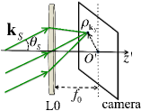
In absence of limits due to diffraction, L0 would focus a plane wave with wave vector 𝐤Ssubscript𝐤𝑆\mathbf{k}_{S} at a point 𝝆𝐤Ssubscript𝝆subscript𝐤𝑆\boldsymbol{\rho}_{\mathbf{k}_{S}}, say, on the camera screen (Fig. 4). Hence the positive frequency part of the quantized field at the camera can be expressed as Note-cryst-refrac

E^S(+)(𝝆𝐤S,t)subscriptsuperscript^𝐸𝑆subscript𝝆subscript𝐤𝑆𝑡\displaystyle\widehat{E}^{(+)}_{S}(\boldsymbol{\rho}_{\mathbf{k}_{S}},t)
exp[iω¯S(tL1(𝐤S)c)]a^S1(𝐤S)proportional-toabsent𝑖subscript¯𝜔𝑆𝑡subscript𝐿1subscript𝐤𝑆𝑐subscript^𝑎subscript𝑆1subscript𝐤𝑆\displaystyle\propto\exp\left[-i\bar{\omega}_{S}\left(t-\frac{L_{1}(\mathbf{k}_{S})}{c}\right)\right]~{}\widehat{a}_{S_{1}}(\mathbf{k}_{S})
+iexp[i𝐤S𝐫0iω¯S(tL2(𝐤S)c)]a^S2(𝐤S),𝑖𝑖subscript𝐤𝑆subscript𝐫0𝑖subscript¯𝜔𝑆𝑡subscript𝐿2subscript𝐤𝑆𝑐subscript^𝑎subscript𝑆2subscript𝐤𝑆\displaystyle\quad+i\exp\left[i\mathbf{k}_{S}\cdot\mathbf{r}_{0}-i\bar{\omega}_{S}\left(t-\frac{L_{2}(\mathbf{k}_{S})}{c}\right)\right]~{}\widehat{a}_{S_{2}}(\mathbf{k}_{S}), (12)

where Lj(𝐤S)subscript𝐿𝑗subscript𝐤𝑆L_{j}(\mathbf{k}_{S}) is the optical path traveled by the mode labeled by 𝐤Ssubscript𝐤𝑆\mathbf{k}_{S} from the nonlinear crystal j𝑗j to the camera (propagation inside the crystals has been neglected), |𝐤S|=ω¯S/csubscript𝐤𝑆subscript¯𝜔𝑆𝑐|\mathbf{k}_{S}|=\bar{\omega}_{S}/c and we have chosen 𝐫01=0subscript𝐫subscript010\mathbf{r}_{0_{1}}=0, 𝐫02𝐫01=𝐫0subscript𝐫subscript02subscript𝐫subscript01subscript𝐫0\mathbf{r}_{0_{2}}-\mathbf{r}_{0_{1}}=\mathbf{r}_{0}.

III.3 Formation of an Image

For the sake of simplicity, we assume that the pump beams are well collimated, uniformly polarized and narrow-band with mean frequency ω¯Psubscript¯𝜔𝑃\bar{\omega}_{P}. In this case, the pump field at the crystal j𝑗j can be represented by VPjexp[i(𝐤P𝐫ω¯Pt)]subscript𝑉subscript𝑃𝑗𝑖subscript𝐤𝑃𝐫subscript¯𝜔𝑃𝑡V_{P_{j}}\exp[i(\mathbf{k}_{P}\cdot\mathbf{r}-\bar{\omega}_{P}t)]. We choose the direction of 𝐤Psubscript𝐤𝑃\mathbf{k}_{P} to be along the direction of the optical axis. Using Eqs. (III), (9) and (III.1) one can show (see Appendix 1) that the quantum state of the field in this system can be approximated by

|ΨketΨabsent\displaystyle\left|\Psi\right\rangle\approx
|vac+tDi𝐤S1𝐤I1[g(ωS1,ωI1)VP1\displaystyle\left|\text{vac}\right\rangle+\frac{t^{\prime}D}{i\hbar}\sum_{\mathbf{k}_{S_{1}}}\sum_{\mathbf{k}_{I_{1}}}\Big{[}g(\omega_{S_{1}},\omega_{I_{1}})V_{P_{1}}
{n=13sinc[(𝐤P𝐤S1𝐤I1)nln/2]}superscriptsubscriptproduct𝑛13sincdelimited-[]subscriptsubscript𝐤𝑃subscript𝐤subscript𝑆1subscript𝐤subscript𝐼1𝑛subscript𝑙𝑛2\displaystyle\big{\{}\prod_{n=1}^{3}\text{sinc}[(\mathbf{k}_{P}-\mathbf{k}_{S_{1}}-\mathbf{k}_{I_{1}})_{n}l_{n}/2]\big{\}}
sinc[(ωS1+ωI1ω¯P)t/2]|𝐤S1S1|𝐤I1I1|0S2|00]\displaystyle\text{sinc}[(\omega_{S_{1}}+\omega_{I_{1}}-\bar{\omega}_{P})t^{\prime}/2]\left|\mathbf{k}_{S_{1}}\right\rangle_{S_{1}}\left|\mathbf{k}_{I_{1}}\right\rangle_{I_{1}}\left|~{}0~{}\right\rangle_{S_{2}}\left|0\right\rangle_{0}\Big{]}
+tDi𝐤S2𝐤I2[g(ωS2,ωI2)VP2exp[i(𝐤P𝐤S2𝐤I2)𝐫0]\displaystyle+\frac{t^{\prime}D}{i\hbar}\sum_{\mathbf{k}_{S_{2}}}\sum_{\mathbf{k}_{I_{2}}}\Big{[}g(\omega_{S_{2}},\omega_{I_{2}})V_{P_{2}}\exp\left[i(\mathbf{k}_{P}-\mathbf{k}_{S_{2}}-\mathbf{k}_{I_{2}})\cdot\mathbf{r}_{0}\right]
exp[iϕI(𝐤~I2)]sinc[(ωS2+ωI2ω¯P)t/2]𝑖subscriptitalic-ϕ𝐼subscript~𝐤subscript𝐼2sincdelimited-[]subscript𝜔subscript𝑆2subscript𝜔subscript𝐼2subscript¯𝜔𝑃superscript𝑡2\displaystyle\exp[-i\phi_{I}(\widetilde{\mathbf{k}}_{I_{2}})]\text{sinc}[(\omega_{S_{2}}+\omega_{I_{2}}-\bar{\omega}_{P})t^{\prime}/2]
{n=13sinc[(𝐤P𝐤S2𝐤I2)nln/2]}superscriptsubscriptproduct𝑛13sincdelimited-[]subscriptsubscript𝐤𝑃subscript𝐤subscript𝑆2subscript𝐤subscript𝐼2𝑛subscript𝑙𝑛2\displaystyle\big{\{}\prod_{n=1}^{3}\text{sinc}[(\mathbf{k}_{P}-\mathbf{k}_{S_{2}}-\mathbf{k}_{I_{2}})_{n}l_{n}/2]\big{\}}
(𝒯(𝝆𝐤~I2)|0S1|𝐤~I2I1|𝐤S2S2|00\displaystyle~{}\Big{(}\mathscr{T}^{\ast}(\boldsymbol{\rho}_{\widetilde{\mathbf{k}}_{I_{2}}})\left|~{}0~{}\right\rangle_{S_{1}}~{}\left|\widetilde{\mathbf{k}}_{I_{2}}\right\rangle_{I_{1}}\left|\mathbf{k}_{S_{2}}\right\rangle_{S_{2}}\left|0\right\rangle_{0}
+(𝝆𝐤~I2)|0S1|0I1|𝐤S2S2|𝐤~I20)],\displaystyle~{}+\mathscr{R}^{{}^{\prime}\ast}(\boldsymbol{\rho}_{\widetilde{\mathbf{k}}_{I_{2}}})\left|~{}0~{}\right\rangle_{S_{1}}~{}\left|0\right\rangle_{I_{1}}\left|\mathbf{k}_{S_{2}}\right\rangle_{S_{2}}\left|\widetilde{\mathbf{k}}_{I_{2}}\right\rangle_{0}\Big{)}\Big{]}, (13)

where g(ωSj,ωIj)=χ(ωSj,ωIj)αS(ωSj)αI(ωIj)exp[i(ωSj+ωIjω¯P)t/2]𝑔subscript𝜔subscript𝑆𝑗subscript𝜔subscript𝐼𝑗𝜒subscript𝜔subscript𝑆𝑗subscript𝜔subscript𝐼𝑗subscriptsuperscript𝛼𝑆subscript𝜔subscript𝑆𝑗subscriptsuperscript𝛼𝐼subscript𝜔subscript𝐼𝑗𝑖subscript𝜔subscript𝑆𝑗subscript𝜔subscript𝐼𝑗subscript¯𝜔𝑃superscript𝑡2g(\omega_{S_{j}},\omega_{I_{j}})=\mbox{\Large$\chi$}(\omega_{S_{j}},\omega_{I_{j}})\alpha^{\ast}_{S}(\omega_{S_{j}})\alpha^{\ast}_{I}(\omega_{I_{j}})\exp[i(\omega_{S_{j}}+\omega_{I_{j}}-\bar{\omega}_{P})t^{\prime}/2], 𝐤~I2subscript~𝐤subscript𝐼2\widetilde{\mathbf{k}}_{I_{2}} is the mirror image of 𝐤I2subscript𝐤subscript𝐼2\mathbf{k}_{I_{2}} with respect to the optical axis (beam axis) of the 4-f system and we have suppressed the normalization coefficients. In the experiment, we choose crystals whose sides are approximately 103superscript10310^{-3}m of length; since the wave vectors are characterized by corresponding optical wavelengths, the terms sinc[(𝐤Pj𝐤Sj𝐤Ij)nln/2]sincdelimited-[]subscriptsubscript𝐤subscript𝑃𝑗subscript𝐤subscript𝑆𝑗subscript𝐤subscript𝐼𝑗𝑛subscript𝑙𝑛2\text{sinc}[(\mathbf{k}_{P_{j}}-\mathbf{k}_{S_{j}}-\mathbf{k}_{I_{j}})_{n}l_{n}/2] in Eq. (III) contribute only when 𝐤Pj𝐤Sj𝐤Ij0subscript𝐤subscript𝑃𝑗subscript𝐤subscript𝑆𝑗subscript𝐤subscript𝐼𝑗0\mathbf{k}_{P_{j}}-\mathbf{k}_{S_{j}}-\mathbf{k}_{I_{j}}\approx 0. This implies that the spatial phase matching condition 𝐤Pj𝐤Sj+𝐤Ijsubscript𝐤subscript𝑃𝑗subscript𝐤subscript𝑆𝑗subscript𝐤subscript𝐼𝑗\mathbf{k}_{P_{j}}\approx\mathbf{k}_{S_{j}}+\mathbf{k}_{I_{j}} holds to a very good accuracy. Furthermore, the term sinc[(ωSj+ωIjω¯P)t/2]sincdelimited-[]subscript𝜔subscript𝑆𝑗subscript𝜔subscript𝐼𝑗subscript¯𝜔𝑃superscript𝑡2\text{sinc}[(\omega_{S_{j}}+\omega_{I_{j}}-\bar{\omega}_{P})t^{\prime}/2] leads to the temporal phase matching condition ω¯PωSj+ωIjsubscript¯𝜔𝑃subscript𝜔subscript𝑆𝑗subscript𝜔subscript𝐼𝑗\bar{\omega}_{P}\approx\omega_{S_{j}}+\omega_{I_{j}}.

The photon counting rate G-1 at a point 𝝆𝐤Ssubscript𝝆subscript𝐤𝑆\boldsymbol{\rho}_{\mathbf{k}_{S}} in the camera is given by

(𝝆𝐤S)Ψ|E^S()(𝝆𝐤S,t)E^S(+)(𝝆𝐤S,t)|Ψ,proportional-tosubscript𝝆subscript𝐤𝑆quantum-operator-productΨsubscriptsuperscript^𝐸𝑆subscript𝝆subscript𝐤𝑆𝑡subscriptsuperscript^𝐸𝑆subscript𝝆subscript𝐤𝑆𝑡Ψ\mathcal{R}(\boldsymbol{\rho}_{\mathbf{k}_{S}})\propto\left\langle\Psi\right|\widehat{E}^{(-)}_{S}(\boldsymbol{\rho}_{\mathbf{k}_{S}},t)\widehat{E}^{(+)}_{S}(\boldsymbol{\rho}_{\mathbf{k}_{S}},t)\left|\Psi\right\rangle, (14)

where |ΨketΨ\left|\Psi\right\rangle is given by Eq. (III.3) and the quantized field is given by Eq. (III.2). It follows from a long but straightforward calculation that apart from a proportionality constant (𝝆𝐤S)subscript𝝆subscript𝐤𝑆\mathcal{R}(\boldsymbol{\rho}_{\mathbf{k}_{S}}) is given by

(𝝆𝐤S)subscript𝝆subscript𝐤𝑆\displaystyle\mathcal{R}(\boldsymbol{\rho}_{\mathbf{k}_{S}}) |VP1|2+|VP2|2absentsuperscriptsubscript𝑉subscript𝑃12superscriptsubscript𝑉subscript𝑃22\displaystyle\approx|V_{P_{1}}|^{2}+|V_{P_{2}}|^{2}
+2|VP1||VP2||𝒯(𝝆𝐤~I)|2subscript𝑉subscript𝑃1subscript𝑉subscript𝑃2𝒯subscript𝝆subscript~𝐤𝐼\displaystyle+2|V_{P_{1}}||V_{P_{2}}||\mathscr{T}(\boldsymbol{\rho}_{\widetilde{\mathbf{k}}_{I}})|
cos[ϕS2(𝐤S)ϕS1(𝐤S)ϕI(𝐤~I)\displaystyle\qquad\cos\Big{[}\phi_{S_{2}}(\mathbf{k}_{S})-\phi_{S_{1}}(\mathbf{k}_{S})-\phi_{I}(\widetilde{\mathbf{k}}_{I})
arg[𝒯(𝝆𝐤~I)]+ϕP+𝐤S𝐫0+C0],\displaystyle\qquad\qquad-\text{arg}[\mathscr{T}(\boldsymbol{\rho}_{\widetilde{\mathbf{k}}_{I}})]+\phi_{P}+\mathbf{k}_{S}\cdot\mathbf{r}_{0}+C_{0}\Big{]}, (15)

where 𝐤~Isubscript~𝐤𝐼\widetilde{\mathbf{k}}_{I} denotes a wave vector that is the mirror image of the wave vector 𝐤I=𝐤P𝐤Ssubscript𝐤𝐼subscript𝐤𝑃subscript𝐤𝑆\mathbf{k}_{I}=\mathbf{k}_{P}-\mathbf{k}_{S} with respect to the optical axis [Fig. 3], |𝐤P|=ω¯P/csubscript𝐤𝑃subscript¯𝜔𝑃𝑐|\mathbf{k}_{P}|=\bar{\omega}_{P}/c, |𝐤S|=ω¯S/csubscript𝐤𝑆subscript¯𝜔𝑆𝑐|\mathbf{k}_{S}|=\bar{\omega}_{S}/c, |𝐤I|=ω¯I/csubscript𝐤𝐼subscript¯𝜔𝐼𝑐|\mathbf{k}_{I}|=\bar{\omega}_{I}/c, 𝝆𝐤~Isubscript𝝆subscript~𝐤𝐼\boldsymbol{\rho}_{\widetilde{\mathbf{k}}_{I}} is the point on the object that is illuminated by the idler mode 𝐤~Isubscript~𝐤𝐼\widetilde{\mathbf{k}}_{I}, ϕSj(𝐤S)=ω¯SLj(𝐤S)/csubscriptitalic-ϕsubscript𝑆𝑗subscript𝐤𝑆subscript¯𝜔𝑆subscript𝐿𝑗subscript𝐤𝑆𝑐\phi_{S_{j}}(\mathbf{k}_{S})=\bar{\omega}_{S}L_{j}(\mathbf{k}_{S})/c, ϕP=arg[VP2]arg[VP1]subscriptitalic-ϕ𝑃argdelimited-[]subscript𝑉subscript𝑃2argdelimited-[]subscript𝑉subscript𝑃1\phi_{P}=\text{arg}[V_{P_{2}}]-\text{arg}[V_{P_{1}}], and C0subscript𝐶0C_{0} includes all other phase terms. Equation (III.3) is the key equation of the theory of imaging.

Let us first consider the situation in which no object is placed in the idler’s path, i.e., when |𝒯|=1𝒯1|\mathscr{T}|=1 and arg[𝒯]=0argdelimited-[]𝒯0\text{arg}[\mathscr{T}]=0. We have already mentioned in Section III.2 that a point on the image plane (camera) has contribution only from one signal mode 𝐤Ssubscript𝐤𝑆\mathbf{k}_{S}. Since the diameter of the signal beam cross-section in the camera is much smaller in dimension than the optical paths Lj(𝐤S)subscript𝐿𝑗subscript𝐤𝑆L_{j}(\mathbf{k}_{S}) and the distance |𝐫0|subscript𝐫0|\mathbf{r}_{0}| between the two crystals, the terms 𝐤S𝐫0subscript𝐤𝑆subscript𝐫0\mathbf{k}_{S}\cdot\mathbf{r}_{0} and ϕSj(𝐤S)subscriptitalic-ϕ𝑆𝑗subscript𝐤𝑆\phi_{Sj}(\mathbf{k}_{S}) can be treated as a slowly varying function of 𝐤Ssubscript𝐤𝑆\mathbf{k}_{S}. Similarly, since the diameter of the first idler beam inside NL2 is much smaller than the distance between the two crystals, one can also neglect the 𝐤~Isubscript~𝐤𝐼\widetilde{\mathbf{k}}_{I} dependence of ϕI(𝐤~I)subscriptitalic-ϕ𝐼subscript~𝐤𝐼\phi_{I}(\widetilde{\mathbf{k}}_{I}). These allow us to write ϕS2(𝐤S)ϕS1(𝐤S)ΔS0subscriptitalic-ϕsubscript𝑆2subscript𝐤𝑆subscriptitalic-ϕsubscript𝑆1subscript𝐤𝑆subscriptΔ𝑆0\phi_{S_{2}}(\mathbf{k}_{S})-\phi_{S_{1}}(\mathbf{k}_{S})\approx\Delta_{S0}, ϕI(𝐤~I)ϕI0subscriptitalic-ϕ𝐼subscript~𝐤𝐼subscriptitalic-ϕ𝐼0\phi_{I}(\widetilde{\mathbf{k}}_{I})\approx\phi_{I0} and 𝐤S𝐫0+C0C0subscript𝐤𝑆subscript𝐫0subscript𝐶0subscriptsuperscript𝐶0\mathbf{k}_{S}\cdot\mathbf{r}_{0}+C_{0}\approx C^{\prime}_{0}, where ΔS0subscriptΔ𝑆0\Delta_{S0}, ϕI0subscriptitalic-ϕ𝐼0\phi_{I0} and C0subscriptsuperscript𝐶0C^{\prime}_{0} are constants. Equation (III.3) now reduces to

(𝝆𝐤S)subscript𝝆subscript𝐤𝑆absent\displaystyle\mathcal{R}(\boldsymbol{\rho}_{\mathbf{k}_{S}})\approx |VP1|2+|VP2|2superscriptsubscript𝑉subscript𝑃12superscriptsubscript𝑉subscript𝑃22\displaystyle|V_{P_{1}}|^{2}+|V_{P_{2}}|^{2}
+2|VP1||VP2|cos[ΔS0ϕI0+ϕP+C0].2subscript𝑉subscript𝑃1subscript𝑉subscript𝑃2subscriptΔ𝑆0subscriptitalic-ϕ𝐼0subscriptitalic-ϕ𝑃subscriptsuperscript𝐶0\displaystyle+2|V_{P_{1}}||V_{P_{2}}|\cos\Big{[}\Delta_{S0}-\phi_{I0}+\phi_{P}+C^{\prime}_{0}\Big{]}. (16)

Since the right-hand side of Eq. (III.3) does not have any 𝐤Ssubscript𝐤𝑆\mathbf{k}_{S} dependence, it is clear that an almost uniformly illuminated beam cross-section would be observed in the camera. The phase term ϕPsubscriptitalic-ϕ𝑃\phi_{P} can be controlled in the experiment and by doing so one can modulate the intensity of the beam spot. It is evident from Eq. (III.3) that by changing the value of ϕPsubscriptitalic-ϕ𝑃\phi_{P}, one can achieve conditions both of constructive and of destructive interference, which are given by the following equations, respectively:

ΔS0ϕI0+ϕPC+C0=2Nπ,subscriptΔ𝑆0subscriptitalic-ϕ𝐼0subscriptitalic-ϕ𝑃𝐶subscriptsuperscript𝐶02𝑁𝜋\displaystyle\Delta_{S0}-\phi_{I0}+\phi_{PC}+C^{\prime}_{0}=2N\pi, (17a)
ΔS0ϕI0+ϕPD+C0=(2N+1)π,subscriptΔ𝑆0subscriptitalic-ϕ𝐼0subscriptitalic-ϕ𝑃𝐷subscriptsuperscript𝐶02𝑁1𝜋\displaystyle\Delta_{S0}-\phi_{I0}+\phi_{PD}+C^{\prime}_{0}=(2N+1)\pi, (17b)

where ϕPCsubscriptitalic-ϕ𝑃𝐶\phi_{PC} and ϕPDsubscriptitalic-ϕ𝑃𝐷\phi_{PD} are values of ϕPsubscriptitalic-ϕ𝑃\phi_{P} for constructive and destructive interferences Note-bs-output , respectively, and N𝑁N is an integer. Thus we have established the relations

ϕS2(𝐤S)ϕS1(𝐤S)ϕI(𝐤~I)+ϕPC+C02Nπ,subscriptitalic-ϕsubscript𝑆2subscript𝐤𝑆subscriptitalic-ϕsubscript𝑆1subscript𝐤𝑆subscriptitalic-ϕ𝐼subscript~𝐤𝐼subscriptitalic-ϕ𝑃𝐶subscriptsuperscript𝐶02𝑁𝜋\displaystyle\phi_{S_{2}}(\mathbf{k}_{S})-\phi_{S_{1}}(\mathbf{k}_{S})-\phi_{I}(\widetilde{\mathbf{k}}_{I})+\phi_{PC}+C^{\prime}_{0}\approx 2N\pi, (18a)
ϕS2(𝐤S)ϕS1(𝐤S)ϕI(𝐤~I)+ϕPD+C0(2N+1)π.subscriptitalic-ϕsubscript𝑆2subscript𝐤𝑆subscriptitalic-ϕsubscript𝑆1subscript𝐤𝑆subscriptitalic-ϕ𝐼subscript~𝐤𝐼subscriptitalic-ϕ𝑃𝐷subscriptsuperscript𝐶02𝑁1𝜋\displaystyle\phi_{S_{2}}(\mathbf{k}_{S})-\phi_{S_{1}}(\mathbf{k}_{S})-\phi_{I}(\widetilde{\mathbf{k}}_{I})+\phi_{PD}+C^{\prime}_{0}\approx(2N+1)\pi. (18b)

When the object is inserted in the idler’s path, it follows from Eqs. (III.3) and (18) that the photon counting rates at a point in the camera under the conditions of constructive and destructive interference are, respectively, given by the formulas

(+)(𝝆𝐤S)superscriptsubscript𝝆subscript𝐤𝑆\displaystyle\mathcal{R}^{(+)}(\boldsymbol{\rho}_{\mathbf{k}_{S}}) |VP1|2+|VP2|2absentsuperscriptsubscript𝑉subscript𝑃12superscriptsubscript𝑉subscript𝑃22\displaystyle\approx|V_{P_{1}}|^{2}+|V_{P_{2}}|^{2}
+2|VP1||VP2||𝒯(𝝆𝐤~I)|cos(arg[𝒯(𝝆𝐤~I)]),2subscript𝑉subscript𝑃1subscript𝑉subscript𝑃2𝒯subscript𝝆subscript~𝐤𝐼argdelimited-[]𝒯subscript𝝆subscript~𝐤𝐼\displaystyle+2|V_{P_{1}}||V_{P_{2}}||\mathscr{T}(\boldsymbol{\rho}_{\widetilde{\mathbf{k}}_{I}})|\cos(\text{arg}[\mathscr{T}(\boldsymbol{\rho}_{\widetilde{\mathbf{k}}_{I}})]), (19a)
()(𝝆𝐤S)superscriptsubscript𝝆subscript𝐤𝑆\displaystyle\mathcal{R}^{(-)}(\boldsymbol{\rho}_{\mathbf{k}_{S}}) |VP1|2+|VP2|2absentsuperscriptsubscript𝑉subscript𝑃12superscriptsubscript𝑉subscript𝑃22\displaystyle\approx|V_{P_{1}}|^{2}+|V_{P_{2}}|^{2}
2|VP1||VP2||𝒯(𝝆𝐤~I)|cos(arg[𝒯(𝝆𝐤~I)]).2subscript𝑉subscript𝑃1subscript𝑉subscript𝑃2𝒯subscript𝝆subscript~𝐤𝐼argdelimited-[]𝒯subscript𝝆subscript~𝐤𝐼\displaystyle-2|V_{P_{1}}||V_{P_{2}}||\mathscr{T}(\boldsymbol{\rho}_{\widetilde{\mathbf{k}}_{I}})|\cos(\text{arg}[\mathscr{T}(\boldsymbol{\rho}_{\widetilde{\mathbf{k}}_{I}})]). (19b)

Equations (19) imply that an image of an absorptive object (arg[𝒯(𝝆𝐤I)]=0argdelimited-[]𝒯subscript𝝆subscript𝐤𝐼0\text{arg}[\mathscr{T}(\boldsymbol{\rho}_{\mathbf{k}_{I}})]=0) and as well as of a phase object (|𝒯(𝝆𝐤I)|=1𝒯subscript𝝆subscript𝐤𝐼1|\mathscr{T}(\boldsymbol{\rho}_{\mathbf{k}_{I}})|=1) would appear in the camera for both constructive and destructive interferences (see LBCRLZ-mandel-im , Fig. 3a). It further follows from Eqs. (19) that apart from a proportionality constant

(+)(𝝆𝐤S)()(𝝆𝐤S)|𝒯(𝝆𝐤~I)|cos(arg[𝒯(𝝆𝐤~I)]),superscriptsubscript𝝆subscript𝐤𝑆superscriptsubscript𝝆subscript𝐤𝑆𝒯subscript𝝆subscript~𝐤𝐼argdelimited-[]𝒯subscript𝝆subscript~𝐤𝐼\displaystyle\mathcal{R}^{(+)}(\boldsymbol{\rho}_{\mathbf{k}_{S}})-\mathcal{R}^{(-)}(\boldsymbol{\rho}_{\mathbf{k}_{S}})\approx|\mathscr{T}(\boldsymbol{\rho}_{\widetilde{\mathbf{k}}_{I}})|\cos(\text{arg}[\mathscr{T}(\boldsymbol{\rho}_{\widetilde{\mathbf{k}}_{I}})]), (20)

implying the background effect due to presence of the terms |VP1|2superscriptsubscript𝑉subscript𝑃12|V_{P_{1}}|^{2} and |VP2|2superscriptsubscript𝑉subscript𝑃22|V_{P_{2}}|^{2} can be eliminated by subtracting the photon counting rate obtained with destructive interference from that obtained with constructive interference (see LBCRLZ-mandel-im , Fig. 3d). It also follows from Eqs. (19) that

(+)(𝝆𝐤S)+()(𝝆𝐤S)2(|VP1|2+|VP2|2).superscriptsubscript𝝆subscript𝐤𝑆superscriptsubscript𝝆subscript𝐤𝑆2superscriptsubscript𝑉subscript𝑃12superscriptsubscript𝑉subscript𝑃22\displaystyle\mathcal{R}^{(+)}(\boldsymbol{\rho}_{\mathbf{k}_{S}})+\mathcal{R}^{(-)}(\boldsymbol{\rho}_{\mathbf{k}_{S}})\approx 2(|V_{P_{1}}|^{2}+|V_{P_{2}}|^{2}). (21)

This means that summing up the photon counting rates obtained by constructive and destructive interferences removes the image (see LBCRLZ-mandel-im , Fig. 3c). Clearly, even if one uses an absorptive object that completely blocks the beam I1subscript𝐼1I_{1}, the summation of the photon counting rates does not change. The fact that the information of the object appears only in the interference term shows that the imaging process is purely quantum mechanical in nature; this point is discussed later in further details.

It is clear from the preceding discussion that a point 𝝆𝐤~Isubscript𝝆subscript~𝐤𝐼\boldsymbol{\rho}_{\widetilde{\mathbf{k}}_{I}} in the object plane is imaged at the point 𝝆𝐤Ssubscript𝝆subscript𝐤𝑆\boldsymbol{\rho}_{\mathbf{k}_{S}} in the image plane, where 𝝆𝐤~Isubscript𝝆subscript~𝐤𝐼\boldsymbol{\rho}_{\widetilde{\mathbf{k}}_{I}} is the point at which a classical plane wave with wave vector 𝐤~Isubscript~𝐤𝐼\widetilde{\mathbf{k}}_{I} would be focused by the lens L1 [see Fig. 3] and 𝝆𝐤Ssubscript𝝆subscript𝐤𝑆\boldsymbol{\rho}_{\mathbf{k}_{S}} is the point where the plane wave characterized by 𝐤Ssubscript𝐤𝑆\mathbf{k}_{S} would be focused by L0. Since 𝐤~Isubscript~𝐤𝐼\widetilde{\mathbf{k}}_{I} is the mirror image of the wave vector 𝐤Isubscript𝐤𝐼\mathbf{k}_{I} with respect to the optical axis [see Fig. 3] and 𝐤Isubscript𝐤𝐼\mathbf{k}_{I} is related to 𝐤Ssubscript𝐤𝑆\mathbf{k}_{S} by the phase matching condition 𝐤I𝐤P𝐤Ssubscript𝐤𝐼subscript𝐤𝑃subscript𝐤𝑆\mathbf{k}_{I}\approx\mathbf{k}_{P}-\mathbf{k}_{S}, the image that appears on the camera is not inverted Note-img-ninv-lens .

III.4 Image Magnification

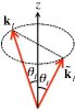
So far we have neglected the effect of refraction at the crystal surface. However, one needs to consider this effect in order to obtain a correct value of the magnification. The wave vectors 𝐤Ssubscript𝐤𝑆\mathbf{k}_{S} and 𝐤~Isubscript~𝐤𝐼\widetilde{\mathbf{k}}_{I} used thus far represent plane waves outside the crystals. The mirror image of 𝐤~Isubscript~𝐤𝐼\widetilde{\mathbf{k}}_{I} with respect to the optical axis z𝑧z is 𝐤Isubscript𝐤𝐼\mathbf{k}_{I} [Fig. 3]. Suppose that the plane waves with wave vectors 𝐤Ssubscript𝐤𝑆\mathbf{k}_{S} and 𝐤Isubscript𝐤𝐼\mathbf{k}_{I} are represented inside the crystal by 𝐤S′′subscriptsuperscript𝐤′′𝑆\mathbf{k}^{\prime\prime}_{S} and 𝐤I′′subscriptsuperscript𝐤′′𝐼\mathbf{k}^{\prime\prime}_{I}, respectively. The phase matching condition can now be expressed as

𝐤S′′+𝐤I′′𝐤P′′,subscriptsuperscript𝐤′′𝑆subscriptsuperscript𝐤′′𝐼subscriptsuperscript𝐤′′𝑃\displaystyle\mathbf{k}^{\prime\prime}_{S}+\mathbf{k}^{\prime\prime}_{I}\approx\mathbf{k}^{\prime\prime}_{P}, (22)

where 𝐤P′′subscriptsuperscript𝐤′′𝑃\mathbf{k}^{\prime\prime}_{P} is the wave vector of the pump field inside the crystal. If 𝐤S′′subscriptsuperscript𝐤′′𝑆\mathbf{k}^{\prime\prime}_{S} and 𝐤I′′subscriptsuperscript𝐤′′𝐼\mathbf{k}^{\prime\prime}_{I} make angles θS′′subscriptsuperscript𝜃′′𝑆\theta^{\prime\prime}_{S} and θI′′subscriptsuperscript𝜃′′𝐼\theta^{\prime\prime}_{I}, respectively, with 𝐤P′′subscriptsuperscript𝐤′′𝑃\mathbf{k}^{\prime\prime}_{P} which is along the optical axis, it follows from Eq. (22) that

ω¯SnS|sinθS′′|ω¯InI|sinθI′′|.subscript¯𝜔𝑆subscript𝑛𝑆subscriptsuperscript𝜃′′𝑆subscript¯𝜔𝐼subscript𝑛𝐼subscriptsuperscript𝜃′′𝐼\displaystyle\bar{\omega}_{S}n_{S}|\sin\theta^{\prime\prime}_{S}|\approx\bar{\omega}_{I}n_{I}|\sin\theta^{\prime\prime}_{I}|. (23)

Let us choose two points on the object which are represented by two-dimensional position vectors 𝝆𝐤~Isubscript𝝆subscript~𝐤𝐼\boldsymbol{\rho}_{\widetilde{\mathbf{k}}_{I}} and 𝝆𝐤~Isubscriptsuperscript𝝆subscriptsuperscript~𝐤𝐼\boldsymbol{\rho}^{\prime}_{\widetilde{\mathbf{k}}^{\prime}_{I}}. Suppose that their images at the camera are represented by the two-dimensional position vectors 𝝆𝐤Ssubscript𝝆subscript𝐤𝑆\boldsymbol{\rho}_{\mathbf{k}_{S}} and 𝝆𝐤Ssubscriptsuperscript𝝆subscriptsuperscript𝐤𝑆\boldsymbol{\rho}^{\prime}_{\mathbf{k}^{\prime}_{S}}, respectively. The magnification is defined by the well known formula

M=|𝝆𝐤S𝝆𝐤S||𝝆𝐤~I𝝆𝐤~I|,𝑀subscript𝝆subscript𝐤𝑆subscriptsuperscript𝝆subscriptsuperscript𝐤𝑆subscript𝝆subscript~𝐤𝐼subscriptsuperscript𝝆subscriptsuperscript~𝐤𝐼\displaystyle M=\frac{|\boldsymbol{\rho}_{\mathbf{k}_{S}}-\boldsymbol{\rho}^{\prime}_{\mathbf{k}^{\prime}_{S}}|}{|\boldsymbol{\rho}_{\widetilde{\mathbf{k}}_{I}}-\boldsymbol{\rho}^{\prime}_{\widetilde{\mathbf{k}}^{\prime}_{I}}|}, (24)

where its positive sign implies that the image is not inverted. As already mentioned, the origins in the object and the image planes are chosen at the points O𝑂O and Osuperscript𝑂O^{\prime} where the corresponding optical axes (beam axes) meet the respective planes [see Figs. 3 and 4]. It readily follows from the theory presented in Section III.3 that Osuperscript𝑂O^{\prime} is the image of O𝑂O. By choosing the points 𝝆𝐤~Isubscriptsuperscript𝝆subscriptsuperscript~𝐤𝐼\boldsymbol{\rho}^{\prime}_{\widetilde{\mathbf{k}}^{\prime}_{I}} and 𝝆𝐤Ssubscriptsuperscript𝝆subscriptsuperscript𝐤𝑆\boldsymbol{\rho}^{\prime}_{\mathbf{k}^{\prime}_{S}} at O𝑂O and Osuperscript𝑂O^{\prime} respectively, we reduce Eq. (24) to the simplified form

M=|𝝆𝐤S||𝝆𝐤~I|.𝑀subscript𝝆subscript𝐤𝑆subscript𝝆subscript~𝐤𝐼\displaystyle M=\frac{|\boldsymbol{\rho}_{\mathbf{k}_{S}}|}{|\boldsymbol{\rho}_{\widetilde{\mathbf{k}}_{I}}|}. (25)

If the signal plane wave 𝐤Ssubscript𝐤𝑆\mathbf{k}_{S}, which is focused by the lens L1 at the point 𝝆𝐤Ssubscript𝝆subscript𝐤𝑆\boldsymbol{\rho}_{\mathbf{k}_{S}}, makes an angle θSsubscript𝜃𝑆\theta_{S} with the optical axis zsuperscript𝑧z^{\prime} (Fig. 4), one has in the small-angle approximation |𝝆𝐤S|=|f0tanθS|f0|θS|subscript𝝆subscript𝐤𝑆subscript𝑓0subscript𝜃𝑆subscript𝑓0subscript𝜃𝑆|\boldsymbol{\rho}_{\mathbf{k}_{S}}|=|f_{0}\tan\theta_{S}|\approx f_{0}|\theta_{S}|. Similarly, one can show that |𝝆𝐤~I|fI|θI|subscript𝝆subscript~𝐤𝐼subscript𝑓𝐼subscript𝜃𝐼|\boldsymbol{\rho}_{\widetilde{\mathbf{k}}_{I}}|\approx f_{I}|\theta_{I}|, where θIsubscript𝜃𝐼\theta_{I} is the angle made by the wave vector 𝐤~Isubscript~𝐤𝐼\widetilde{\mathbf{k}}_{I} with the optical axis [Fig. 3]. It now follows from Eq. (25) that

M=f0|θS|fI|θI|.𝑀subscript𝑓0subscript𝜃𝑆subscript𝑓𝐼subscript𝜃𝐼\displaystyle M=\frac{f_{0}|\theta_{S}|}{f_{I}|\theta_{I}|}. (26)

Since 𝐤Ssubscript𝐤𝑆\mathbf{k}_{S} and 𝐤Isubscript𝐤𝐼\mathbf{k}_{I} are related to 𝐤S′′subscriptsuperscript𝐤′′𝑆\mathbf{k}^{\prime\prime}_{S} and 𝐤I′′subscriptsuperscript𝐤′′𝐼\mathbf{k}^{\prime\prime}_{I}, respectively, by refraction at the crystal surface, using Snell’s law one obtains

nSsinθS′′=n0sinθS,nIsinθI′′=n0sinθI,formulae-sequencesubscript𝑛𝑆subscriptsuperscript𝜃′′𝑆subscript𝑛0subscript𝜃𝑆subscript𝑛𝐼subscriptsuperscript𝜃′′𝐼subscript𝑛0subscript𝜃𝐼\displaystyle n_{S}\sin\theta^{\prime\prime}_{S}=n_{0}\sin\theta_{S},\quad n_{I}\sin\theta^{\prime\prime}_{I}=n_{0}\sin\theta_{I}, (27)

where we have used the fact that 𝐤Isubscript𝐤𝐼\mathbf{k}_{I} and 𝐤~Isubscript~𝐤𝐼\widetilde{\mathbf{k}}_{I} make the same angle with the optical axis [Fig. 3] and the refractive index of air (n0subscript𝑛0n_{0}) has practically the same value for signal and idler. From Eqs. (23) and (27), it immediately follows that ω¯S|sinθS|ω¯I|sinθI|subscript¯𝜔𝑆subscript𝜃𝑆subscript¯𝜔𝐼subscript𝜃𝐼\bar{\omega}_{S}|\sin\theta_{S}|\approx\bar{\omega}_{I}|\sin\theta_{I}|. In the small-angle limit, we thus obtain

ω¯S|θS|ω¯I|θI|.subscript¯𝜔𝑆subscript𝜃𝑆subscript¯𝜔𝐼subscript𝜃𝐼\displaystyle\bar{\omega}_{S}|\theta_{S}|\approx\bar{\omega}_{I}|\theta_{I}|. (28)

From Eqs. (26) and (28) one finds that

M=f0ω¯IfIω¯S=f0λ¯SfIλ¯I.𝑀subscript𝑓0subscript¯𝜔𝐼subscript𝑓𝐼subscript¯𝜔𝑆subscript𝑓0subscript¯𝜆𝑆subscript𝑓𝐼subscript¯𝜆𝐼\displaystyle M=\frac{f_{0}\bar{\omega}_{I}}{f_{I}\bar{\omega}_{S}}=\frac{f_{0}\bar{\lambda}_{S}}{f_{I}\bar{\lambda}_{I}}. (29)

Clearly, magnification of the imaging system depends on the ratio of the average wavelength of the signal to that of the idler. The dependence of the magnification on both wavelengths is a remarkable feature of our imaging process.

IV Conclusion

We have theoretically analyzed a recently demonstrated LBCRLZ-mandel-im quantum imaging technique. Although the experimental setup resembles an ordinary two-arm interferometer, the principle behind the imaging is purely quantum mechanical. If one imagines a classical two-arm interferometer in one of whose arms an absorptive object is placed, both the interference term and the intensity contribution from the arm containing the object would depend on the transmissivity of the object. In our experiment, on the other hand, the intensity contribution from any of the crystals does not depend on the transmissivity of the object. It is evident from Eqs. (19) that the information of the object is present only in the interference term. This also shows that the interference of signal beams is not due to the effect of induced emission (see also ZWM-ind-coh-PRL ; WM-ind-coh-cl-q ). This interference can only be explained by indistinguishability of the signal photon paths and hence the imaging process is directly related to wave-particle duality of photons.

In this context, let us also have a close look at Eq. (III.3), which provides us with an expression for the quantum state |ΨketΨ\left|\Psi\right\rangle that has been used for explaining the imaging process. Since the pump source used in the experiment is a narrow-band laser, this state is obtained (see Appendix 1) from the tensor product of the individual states, |ψ1ketsubscript𝜓1\left|\psi_{1}\right\rangle and |ψ2ketsubscript𝜓2\left|\psi_{2}\right\rangle, generated by the crystals under the alignment-condition imposed by Eq. (III.1). This tensor product together with the alignment-condition implies the effect of induced emission. However, when the higher order terms present in |ψ1ketsubscript𝜓1\left|\psi_{1}\right\rangle and |ψ2ketsubscript𝜓2\left|\psi_{2}\right\rangle can be neglected, the state |ΨketΨ\left|\Psi\right\rangle becomes identical with a state obtained by linear superposition of |ψ1ketsubscript𝜓1\left|\psi_{1}\right\rangle and |ψ2ketsubscript𝜓2\left|\psi_{2}\right\rangle under the same alignment-condition (see Appendix 1). Since such a superposition is only allowed when there is no effect of induced emission, it is clear that photons generated by spontaneous parametric down conversion play the key role in our imaging process Note-ind-em .

Finally, although it is obvious, we would like to point out that the principle of our imaging also works if an entirely different lens system (or no lens system) is used in the experiment. A different lens system would only lead to a different value of the image magnification. Equation (29) shows that this magnification is equal to the product of two ratios: the ratio of focal lengths (f0/fIsubscript𝑓0subscript𝑓𝐼f_{0}/f_{I}) and the ratio of wavelengths (λ¯S/λ¯Isubscript¯𝜆𝑆subscript¯𝜆𝐼\bar{\lambda}_{S}/\bar{\lambda}_{I}). The most remarkable feature of this result is the presence of two mean wavelengths in the formula of magnification. This is a consequence of (a) the fact that the object is illuminated by photons of one mean wavelength while the camera detects photons of the other wavelength and (b) the phase-matching condition [see Eq. (23)]. The use of a different lens system in the setup might lead to a different expression for the image magnification; however, a dependence on two average wavelengths would always be present.

Acknowledgements

The authors thanks M. Horne for many discussions. This project was supported by ÖAW, the European Research Council (ERC Advanced grant no. 227844 “QIT4QAD”, and SIQS grant no. 600645 EU-FP7-ICT), and the Austrian Science Fund (FWF) with SFB F40 (FOQUS) and W1210-2 (CoQus).

Appendix 1

In this appendix, we illustrate the procedure used for obtaining Eq. (III.3). We present a single-mode analysis, because the procedure does not change when all the modes present in the quantized fields are considered. The single-mode and scalar version of Eq. (III) can be represented in the form

|ψj=|vac+Gj|1Sj|1Ij+,ketsubscript𝜓𝑗ketvacsubscript𝐺𝑗subscriptket1subscript𝑆𝑗subscriptket1subscript𝐼𝑗\displaystyle\left|\psi_{j}\right\rangle=\left|\text{vac}\right\rangle+G_{j}\left|1\right\rangle_{S_{j}}~{}\left|1\right\rangle_{I_{j}}+\dots, (30)

where j=1,2𝑗12j=1,2, the time dependence is suppressed, the coefficients are collectively denoted by Gjsubscript𝐺𝑗G_{j} and the dots represent higher order terms containing higher powers of Gjsubscript𝐺𝑗G_{j}.

The single-mode version of Eq. (III.1) is given by

a^I2=[𝒯a^I1+a^0]eiϕI.subscript^𝑎subscript𝐼2delimited-[]𝒯subscript^𝑎subscript𝐼1superscriptsubscript^𝑎0superscript𝑒𝑖subscriptitalic-ϕ𝐼\displaystyle\widehat{a}_{I_{2}}=\left[\mathscr{T}\widehat{a}_{I_{1}}+\mathscr{R}^{\prime}\widehat{a}_{0}\right]~{}e^{i\phi_{I}}. (31)

From Eq. (31), one immediately obtains that

|1I2=[𝒯|1I1|00+|0I1|10]eiϕI.subscriptket1subscript𝐼2delimited-[]superscript𝒯subscriptket1subscript𝐼1subscriptket00superscriptsubscriptket0subscript𝐼1subscriptket10superscript𝑒𝑖subscriptitalic-ϕ𝐼\displaystyle\left|1\right\rangle_{I_{2}}=\left[\mathscr{T}^{\ast}\left|1\right\rangle_{I_{1}}\left|0\right\rangle_{0}+\mathscr{R}^{\prime\ast}\left|0\right\rangle_{I_{1}}\left|1\right\rangle_{0}\right]~{}e^{-i\phi_{I}}. (32)

Now using Eqs. (30) and (32), one can write

|ψ1=|vac+G1|1S1|1I1|0S2|00+ketsubscript𝜓1ketvacsubscript𝐺1subscriptket1subscript𝑆1subscriptket1subscript𝐼1subscriptket0subscript𝑆2subscriptket00\displaystyle\left|\psi_{1}\right\rangle=\left|\text{vac}\right\rangle+G_{1}\left|1\right\rangle_{S_{1}}~{}\left|1\right\rangle_{I_{1}}\left|0\right\rangle_{S_{2}}~{}\left|0\right\rangle_{0}+\dots (33a)
|ψ2=|vac+G2eiϕI[𝒯|0S1|1I1|1S2|00\displaystyle\left|\psi_{2}\right\rangle=\left|\text{vac}\right\rangle+G_{2}e^{-i\phi_{I}}\big{[}\mathscr{T}^{\ast}\left|0\right\rangle_{S_{1}}\left|1\right\rangle_{I_{1}}\left|1\right\rangle_{S_{2}}\left|0\right\rangle_{0}
+|0S1|0I1|1S2|10]+.\displaystyle\qquad\qquad\qquad\qquad+\mathscr{R}^{\prime\ast}\left|0\right\rangle_{S_{1}}\left|0\right\rangle_{I_{1}}\left|1\right\rangle_{S_{2}}\left|1\right\rangle_{0}\big{]}+\dots. (33b)

Since both crystals are pumped by beams generated by a laser source (not a single photon source), the quantum state of light in the system is given by |Ψ=|ψ1|ψ2ketΨketsubscript𝜓1ketsubscript𝜓2\left|\Psi\right\rangle=\left|\psi_{1}\right\rangle\left|\psi_{2}\right\rangle, i.e., by

|ΨketΨ\displaystyle\left|\Psi\right\rangle =|vac+G1|1S1|1I1|0S2|0I2absentketvacsubscript𝐺1subscriptket1subscript𝑆1subscriptket1subscript𝐼1subscriptket0subscript𝑆2subscriptket0subscript𝐼2\displaystyle=\left|\text{vac}\right\rangle+G_{1}\left|1\right\rangle_{S_{1}}~{}\left|1\right\rangle_{I_{1}}\left|0\right\rangle_{S_{2}}~{}\left|0\right\rangle_{I_{2}}
+G2eiϕI[𝒯|0S1|1I1|1S2|00\displaystyle+G_{2}e^{-i\phi_{I}}\big{[}\mathscr{T}^{\ast}\left|0\right\rangle_{S_{1}}\left|1\right\rangle_{I_{1}}\left|1\right\rangle_{S_{2}}\left|0\right\rangle_{0}
+|0S1|0I1|1S2|10]\displaystyle+\mathscr{R}^{\prime\ast}\left|0\right\rangle_{S_{1}}\left|0\right\rangle_{I_{1}}\left|1\right\rangle_{S_{2}}\left|1\right\rangle_{0}\big{]}
+higher order terms,higher order terms\displaystyle+\text{higher order terms}, (34)

where the higher order terms contains higher second or higher powers of the coefficients G𝐺G. Since the rate of down conversion is very small, the these higher order terms can be neglected. Hence the state |ΨketΨ\left|\Psi\right\rangle can be approximated by (neglecting the normalization coefficients)

|ΨketΨ\displaystyle\left|\Psi\right\rangle |vac+G1|1S1|1I1|0S2|0I2absentketvacsubscript𝐺1subscriptket1subscript𝑆1subscriptket1subscript𝐼1subscriptket0subscript𝑆2subscriptket0subscript𝐼2\displaystyle\approx\left|\text{vac}\right\rangle+G_{1}\left|1\right\rangle_{S_{1}}~{}\left|1\right\rangle_{I_{1}}\left|0\right\rangle_{S_{2}}~{}\left|0\right\rangle_{I_{2}}
+G2eiϕI[𝒯|0S1|1I1|1S2|00\displaystyle+G_{2}e^{-i\phi_{I}}\big{[}\mathscr{T}^{\ast}\left|0\right\rangle_{S_{1}}\left|1\right\rangle_{I_{1}}\left|1\right\rangle_{S_{2}}\left|0\right\rangle_{0}
+|0S1|0I1|1S2|10].\displaystyle\qquad+\mathscr{R}^{\prime\ast}\left|0\right\rangle_{S_{1}}\left|0\right\rangle_{I_{1}}\left|1\right\rangle_{S_{2}}\left|1\right\rangle_{0}\big{]}. (35)

Equation (III.3) is the multi-mode version of Eq. (Appendix 1).

It is to be noted that the form of |ΨketΨ\left|\Psi\right\rangle given by Eq. (Appendix 1) can also be obtained by linear superposition of the states given by Eqs. (33a) and (33a), if one neglects the higher order terms. It is thus clear that if the experimental conditions are such that the contribution of these higher order terms is much smaller than that of the first order terms to a measurement of our interest, the measurement would yield the same result as in a case when the state |ΨketΨ\left|\Psi\right\rangle must be obtained by superposing |ψ1ketsubscript𝜓1\left|\psi_{1}\right\rangle and |ψ2ketsubscript𝜓2\left|\psi_{2}\right\rangle.

References

  • (1)

References and Notes

  • (2) N. Bohr,“Discussion with Einstein on epistemological problems in atomic physics,” Albert Einstein: Philosopher Scientist, vol. 1, P. A. Schilpp Ed. (1949).
  • (3) N. Bohr, “Das Quantenpostulat und die neuere Entwicklung der Atomistik,” Naturwissenschaften 16, 245-257 (1928).
  • (4) J.-M. Lev́y-Leblond, “A Quantum Credo,” Physica B 151, 378-380 (1988).
  • (5) The lowest-order interference has been referred to as both second-order MW and first-order G-1 in the literature.
  • (6) R. P. Feynman, R. B. Leighton and M. Sands, The Feynman Lectures on Physics, Vol. III, (Addison-Wesley Publishing Company, New York, USA 1966).
  • (7) D. M. Greenberger and A. Yasin, “Simultaneous wave and particle knowledge in a neutron interferometer,” Phys. Lett. A 128, 391-394 (1988).
  • (8) L. Mandel, “Coherence and indistinguishability”, Opt. Lett. 16, 1882 (1991).
  • (9) G. Jaeger, A. Shimony and L. Vaidman, “Two interferometric complementarities”, Phys. Rev. A 51, 54 (1995).
  • (10) B-G. Englert, “Fringe visibility and which-way information: an inequality”, Phys. Rev. Lett. 77, 2154 (1996).
  • (11) M. Arndt, O. Nairz, J. Vos-Andreae, C. Keller, G. v.d. Zouw and A. Zeilinger,“Wave particle duality of C60 molecules,” Nature 401, 680-682 (1999).
  • (12) G. B. Lemos, V. Borish, G. D. Cole, S. Ramelow, R. Lapkiewicz and A. Zeilinger, “Quantum imaging with undetected photons,” Nature 512, 409-412 (2014).
  • (13) X. Y. Zou, L. J. Wang and L. Mandel, “Induced Coherence and Indistinguishability in Optical Interference,” Phys. Rev. Lett. 67, 318-321 (1991).
  • (14) L. J. Wang, X. Y. Zou and L. Mandel, “Induced Coherence without Induced Emission,” Phys. Rev. A 44, 4614-4622 (1991).
  • (15) C. K. Hong and L. Mandel, “Theory of parametric down conversion of light,” Phys. Rev. A 31, 2409-2418 (1985).
  • (16) Quantization of electromagnetic fields inside a nonlinear crystal is a non-trivial problem. However, when the nonlinearities are not high, the field is often represented in a form which is analogous to that of the free quantized field (see, for example, MW , Ch. 22).
  • (17) R. Ghosh, C. K. Hong, Z. Y. Ou and L. Mandel, “Interference of two photons in parametric down conversion,” Phys. Rev. A 34, 3962-3968 (1985).
  • (18) S. P. Walborn, C. H. Monken, S. Pádua and P. H. Souto Ribeiro, “Spatial correlations in parametric down-conversion,” Phys. Rep. 495, 87-139 (2010).
  • (19) We assume that almost the entire volume of each crystal is illuminated by the pump beam.
  • (20) L. Mandel and E. Wolf, Optical Coherence and Quantum Optics (Cambridge, Cambridge University Press, 1995).
  • (21) The photons are detected outside the crystals, whereas the phase matching conditions represent criteria inside the crystals. Hence the signal wave vectors used in Eq. (III.2) are related to the ones used in Eq. (III.3) by the refraction that occurs at the crystal surface. In this subsection, we neglect the effect of this refraction for simplicity. This effect is considered in Section III.4, where we determine the image magnification.
  • (22) R. J. Glauber, “The quantum theory of optical coherence” Phys. Rev. 130, 2529 (1963).
  • (23) When constructive interference is observed in one of the outputs of the beam splitter, destructive interference occurs in the other output. Because of this changing values of ϕPsubscriptitalic-ϕ𝑃\phi_{P} from ϕPCsubscriptitalic-ϕ𝑃𝐶\phi_{PC} to ϕPDsubscriptitalic-ϕ𝑃𝐷\phi_{PD} can be avoided during the experiment by collecting both outputs of the beam splitter. However, it must be noted that coincidence counts are never detected in this experiment. Detection of coincidence counts are required for investigating higher order interference phenomena (see, for example, WZM-ind-coh-PRA ; BKKC-pdc-fourth-interf ).
  • (24) It is to be noted that by changing the lens system in the experimental setup, it is possible to change the relation between 𝐤~Isubscript~𝐤𝐼\widetilde{\mathbf{k}}_{I} and 𝐤Isubscript𝐤𝐼\mathbf{k}_{I} but not the phase matching condition. In principle, it is thus possible to obtain an inverted image by using a different lens system.
  • (25) H. M. Wiseman and K. Mølmer, “Induced coherence with and without induced emission,” Phys. Lett. A 270, 245-248 (2000).
  • (26) The higher order terms present in |ψ1ketsubscript𝜓1\left|\psi_{1}\right\rangle and |ψ2ketsubscript𝜓2\left|\psi_{2}\right\rangle contain higher (4 or more) photon states. Because of this the effect of induced emission can be observed in certain phenomena (see, for example, LSGHOG-ind-emiss ) where the lower photon-number states do not contribute (i.e., one can no longer neglect the higher order terms).
  • (27) A. V. Burlakov, D. N. Klyshko, S. P. Kulik and M. V. Chekhova, “Fourth-order interference between independent biphotons,” JETP Lett. 69, 831-838 (1999).
  • (28) B. H. Liu, F. W. Sun, Y. X. Gong, Y. F. Huang, Z. Y. Ou and G. C.Guo, “Investigation of the role of indistinguishability in photon bunching and stimulated emission,” Phys. Rev. A 79, 053846 (2009).