Experimental protection of 2-qubit quantum gates against environmental noise by dynamical decoupling
Abstract
Hybrid systems consisting of different types of qubits are promising for building quantum computers if they combine useful properties of their constituent qubits. However, they also pose additional challenges if one type of qubits is more susceptible to environmental noise than the others. Dynamical decoupling can help to protect such systems by reducing the decoherence due to the environmental noise, but the protection must be designed such that it does not interfere with the control fields driving the logical operations. Here, we test such a protection scheme on a quantum register consisting of the electronic and nuclear spins of a nitrogen-vacancy center in diamond. The results show that processing is compatible with protection: The dephasing time was extended almost to the limit given by the longitudinal relaxation time of the electron spin.
pacs:
03.67.Pp,03.67.Lx–Introduction. Choosing the most suitable qubit systems and implementing high-precision quantum gate operations on them may be considered as the main challenges for building quantum computers that will be capable of solving certain problems qualitatively faster than classical computers nielsen ; Stolze:2008xy . In every physical realization, environmental noise is present, which degrades the information stored in the quantum systems. Several techniques have been developed for protecting quantum systems against this effect, including passive schemes like decoherence-free subspaces 3045 or active techniques like dynamical decoupling (DD) 5003 ; suter2012 ; Paolo199977 . So far, these techniques have been applied mostly to the protection of quantum states in quantum memories liu2009 ; hanson2010 ; cory2011 ; PhysRevLett.106.040501 ; nature_514_72 ; shim12 . However, similar protection is also required for quantum information processing. Here, the protection must be designed in such a way that it decouples the protected system from environmental noise, but not from the control fields that are applied for driving the gate operations. Experimental implementations of protected single-qubit gates and some special 2-qubit gates, such as a controlled-NOT (CNOT) gate, were recently reported prar2012 ; PhysRevLett.112.050502 ; dobrovitski2012 ; Natcomm3254 , but so far no scheme was demonstrated that can be applied to arbitrary two-qubit gates in different physical qubit systems.
Implementing quantum computing in hybrid systems is a promising strategy for building quantum computers, as it increases the range of possible systems and allows one to combine useful properties of different types of qubits PhysRevLett.105.140503 ; PhysRevLett.105.140502 ; PhysRevLett.105.140501 ; PhysRevB.82.024413 . As a typical hybrid system, the nitrogen vacancy (NV) center in diamond consists of an electronic spin and a nitrogen nuclear spin and combines several useful properties for a quantum register. It also poses some challenges, mostly because the characteristic properties of the two types of spins differ by many orders of magnitude. For example, the natural coherence time at room temperature of the electron spin is of the order of 1 s, while that of the nuclear spin is ms dobrovitski2012 . The electron spin dephasing time is usually shorter than typical durations of gates applied to the nitrogen spin. The critical gate operations in such a system are therefore the two-qubit gates in which the electron spin is the control quit, while the nuclear spin is the target qubit: In this situation, the relatively slow Rabi frequency of the nuclear spin results in a long duration of the gate, during which the whole quantum information must be conserved, including superpositions of different basis states of the electron spin.
It is possible to apply DD pulses that act parallel to the control field driving the targeted nuclear spin dobrovitski2012 . However, since the DD pulses interchange the computational basis states of the control qubit (the electron spin), the segments of the control field separated by the DD pulses implement two gates with different control conditions. Obtaining the targeted evolution requires therefore careful synchronization of the DD pulses with the internal system evolution. In some systems, specific properties of the Hamiltonian allow one to design DD sequences such that they protect the system from environmental noise and simultaneously implement a useful gate operation Natcomm3254 . However, this approach is very specific to the system and requires that the quantum system can be simulated classically. It is therefore difficult to extend this approach to large quantum registers.
Here, we present a strategy that avoids these limitations and can be applied to arbitrary gate operations with minimal overhead. We demonstrate the scheme for the case of a 2-qubit system, where the duration of one gate is long enough that decoherence destroys a significant part of the quantum information, unless DD is applied to protect it. Compared to existing schemes, our approach can implement arbitrary 2-qubit gates and does not require fine-tuning to system parameters. It requires that the control field driving the gate operation is split into serval segments that can be inserted into the delays of the DD sequence. The segments have to be adjusted to take the effect of the DD pulses into account, which interchange the computational basis states and therefore the condition for the controlled 2-qubit gate.
–Experimental protocol and results. We illustrate this basic idea for the case of a controlled rotation, CR. The unitary operation for this gate can be represented as
| (1) |
where , and and represent matrices corresponding to the unit operator, the zero matrix and a rotation matrix around the -axis, where denotes the -component of the Pauli matrix.
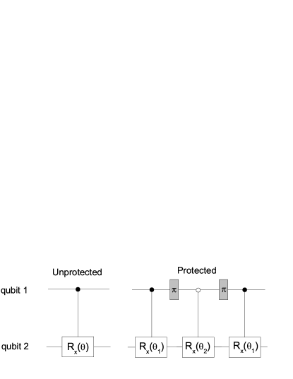
Fig.1 shows the circuit models of the CR gates. The left-hand part represents the unprotected version, while the right-hand side represents the protected gate for the simplest DD sequence consisting of two refocusing pulses. Filled circles indicate that the operation is performed on the subspace where the control qubit is in the logical state , empty circles stand for the control condition . When , becomes the CNOT gate, with an additional phase gate on qubit 1 and an overall phase.
For the experimental implementation, we chose a 4-level system out of the 9-level system composed by the electronic and nuclear spins of the NV center in diamond shown in Fig. 2. If the magnetic field is oriented along the NV symmetry axis, the Hamiltonian of the NV center can be written as arXiv:1405.2696
| (2) |
Here and are the -components of the spin-1 operators for the electron and nitrogen (14N) nuclear spins, respectively. The zero-field splitting is GHz, the nuclear quadrupolar splitting is MHz, and the hyperfine coupling is MHz PhysRevB.89.205202 ; PhysRevB.47.8816 . The electronic gyromagnetic ratio is MHz/G, and the nuclear gyromagnetic ratio kHz/G. The strength of the field in our experiment was about G.
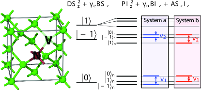
In the 9-dimensional Hilbert space of the electronic and nuclear spins, we chose two different 2-qubit systems to implement the gates. In Fig. 2, they are denoted as and , respectively. In each system, we use the electron spin as the control qubit (qubit 1), while the nuclear spin of the nitrogen represents the target qubit (qubit 2). The logical states for the two qubits correspond to
| (3) |
where the minus sign refers to system and the plus sign to system . Table 1 lists the measured transition frequencies of the nuclear spin and the corresponding Rabi frequencies.
| Transition | Rabi | |
| frequency (MHz) | frequency (kHz) | |
| System a | ||
| System b | ||
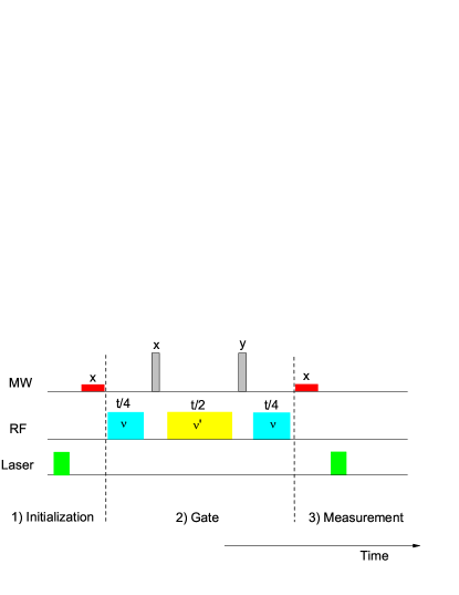
In the experiment, we used a 12C enriched diamond as the sample, so that decoherence due to 13C nuclear spins is small. The experiment was performed at room temperature. Fig. 3 shows the experimental procedure and the pulse sequence. Since the electron spin decoheres on a much shorter timescale than the nuclear spin, it is sufficient to apply DD to the electron spin transitions (qubit 1). This is done in parallel to the controlled rotation of qubit 2. The controlled rotation of qubit 2 is interrupted during the application of the DD pulses, which are several orders of magnitude shorter than the duration of the nuclear spin gate operations (10 ns vs. ). The DD pulses are hard -pulses around the - or - axis, as indicated above the rectangles in Fig. 3, with a Rabi frequency of about MHz. For this demonstration experiment, we used only two DD pulses. To make it symmetric with respect to the initial condition, we alternated the rotation axes between and . To turn this into a cyclic operation (generating a unit operation), it has to be combined with a rotation around the -axis, which we implemented as a phase shift of the subsequent pulses.
In step 1), we prepared the input state for the CR gate. The laser pulse initializes the electronic spin in its ground state , while the nuclear spin is unpolarized. The first microwave (MW) pulse drives selectively the transition, with a flip angle around the -axis. The resulting input state is
| (4) |
written in the computation basis (3) but omitting the index. In this state, the control qubit is in a superposition of and . The CR gate drives the transition labelled in Fig. 2 if the control condition is 0 and the transition labelled if the control condition is 1.
For the readout, we measure the population of the state of the electron spin. To measure the effect of the RF pulse, which affects only the nuclear spin, we therefore need to transfer the information from the nuclear to the electron spin system. For this purpose, we use again a selective MW pulse that rotates the transition around the -axis, by a flip angle . As a function of the rotation angle of the CR gate, the expected signal (i.e. the occupation probability for the -state in the computational space) is
| (5) |
for an ideal gate. In the case of an unprotected gate, the environmental perturbation causes dephasing of the electronic spin state. For a Markovian environment, the off-diagonal elements of the electron spin qubit decay as . This changes the detected signal to
| (6) |
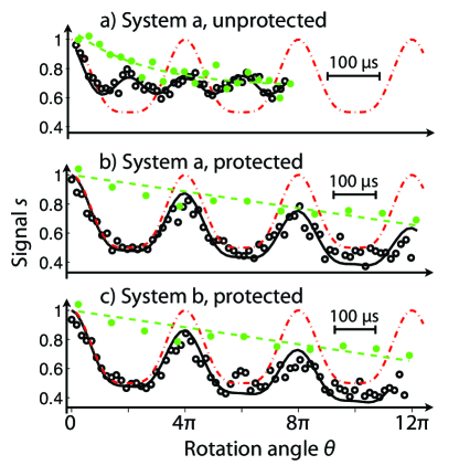
We implemented the unprotected gate by setting and switching off the DD pulses in the sequence in Fig. 3. Fig. 4 (a) illustrates the resulting signal when the unprotected CR gate was implemented with control state in system . The horizontal axis gives the rotation angle of the CR gate , where is the Rabi frequency of the nuclear spin transition. While the ideal gate generates a signal that is periodic in with a period of , the dephasing of the electron spin eliminates this signal component over a time scale of the order of the decay time of the input state without DD pulses. The remaining signal component is periodic with 2, in agreement with Eq. (6). The measured data for the CR gate are marked as empty circles, and the theoretical expectation for the ideal gate is shown as the dash-dotted curve. The solid curve shows the function from Eq. (6) and is in good agreement with the experimental data. Clearly, the dephasing time in this system is too short to allow the implementation of a nontrivial gate, such as CNOT, with sufficient precision. In addition, we measured the decay of the initial state due to relaxation, without applying a gate operation. The resulting data points are shown as filled green circles.
Figs. 4 (b-c), show the corresponding data obtained by the protected CR gate in systems and . The total rotation angle is . To evaluate the performance of the gate, we first measured the decay of the input state protected by the DD pulses. The results are shown in Fig. 4 (b-c) as filled green circles. Over the measured time scale, the experimental data points decay with a time constant of ms, mainly from longitudinal relaxation () and experimental errors. For the protected gate, we used the same decay function and superimposed it over the experimental data points in figures (b-c). The experimental data points can then be fitted with , even for times much longer than the dephasing time scale in the unprotected gate shown in figure Figs. 4 (a), using pure depahsing times of 4 ms.
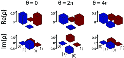
A precise check of the performance of the gate operation could be performed by quantum process tomography. However, this requires the application of SWAP operations consisting of the CR gates that we are evaluating. We therefore only checked the state of the control qubit after the gate operation by quantum state tomography. The CR gate is an entangling gate. However, when the rotation angle is an even multiple of , the CR gate (1) becomes the identity or phase gate for qubit 1, the electronic qubit can be separated from the nuclear spin. At these points, we can reconstruct the state of the electronic qubit by treating it as a single qubit. We implemented quantum state tomography for , and . To reconstruct each state, we used five measurements with different MW pulses in step 3): no pulse, and pulse along , , and , respectively. Fig. 5 illustrates the results. One can clearly observe the effect of the -rotation i.e., phase flip, in the results for .
We compared the experimentally measured states with the ideal states by calculating the fidelity and obtained the values , and for , and , respectively. We can attribute the difference between the experimental and ideal results mostly to longitudinal relaxation, which was measured to be ms by the standard MW pulse sequences and cannot be reversed by dynamical decoupling, and to experimental imperfections.
In addition to the experiments discussed here, we applied the protected CR gate also to other input states and found good agreement with the theoretical predictions. In those cases, where the initial state does not contain coherence of the electron spin, the unprotected gate also works relatively well PhysRevA.87.012301 ; dobrovitski2012 . The resulting evolution is described by Eq. (6) with , and it corresponds to the results shown in Fig. 4 (a) for .
–Conclusion. We have demonstrated the protection of 2-qubit gate operations by dynamical decoupling by combining the control field with dynamical decoupling of the control qubit, which otherwise undergoes rapid dephasing. The protocol can be generalized for multiple-qubit gates, e.g., to NV centers in natural abundance diamond samples, where 13C nuclear spins can act as qubits. The same strategy and techniques should be helpful for implementing quantum control in other quantum systems, in particular for hybrid systems. In future work, we plan to generalize this scheme and use more advanced DD sequences, such as the KDD sequence suter2011 .
Acknowledgments.– JZ acknowledges F. D. Brandao for helpful discussions. This work is supported the DFG through Su 192/19-2.
References
- (1) M. Nielsen and I. Chuang, Quantum Computation and Quantum Information (Cambridge University Press, Cambridge, 2000).
- (2) J. Stolze and D. Suter, Quantum Computing: A Short Course from Theory to Experiment (Wiley-VCH, Berlin, 2nd edition, 2008).
- (3) D. A. Lidar, I. L. Chuang, and K. B. Whaley, Phys. Rev. Lett. 81, 2594 (1998).
- (4) L. Viola and S. Lloyd, Phys. Rev. A 58, 2733 (1998).
- (5) A. M. Souza, G. A. Alvarez, and D. Suter, Phil. Trans. R. Soc. A 370, 4748 (2012).
- (6) P. Zanardi, Physics Letters A 258, 77 (1999)
- (7) J. Du, X. Rong, N. Zhao, Y. Wang, J. Yang, and R. B. Liu, Nature 421, 1265 (2009).
- (8) G. deLange, Z. H. Wang, D. Riste, V. V. Dobrovitski, and R. Hanson, Science 330, 60 (2010).
- (9) C. A. Ryan, J. S. Hodges, and D. G. Cory, Phys. Rev. Lett. 105, 200402 (2010).
- (10) Y. Wang, X. Rong, P. Feng, W. Xu, B. Chong, J.-H. Su, J. Gong, and J. Du, Phys. Rev. Lett. 106, 040501 (2011).
- (11) C. Zu, W.-B. Wang, L. He, W.-G. Zhang, C.-Y. Dai, F. Wang, and L.-M. Duan, Nature 514, 72 (2014).
- (12) J. Shim, I. Niemeyer, J. Zhang, and D. Suter, Eur. Phys. Lett. 99, 40004 (2012).
- (13) A. M. Souza, G. A. Alvarez, and D. Suter, Phys. Rev. A 86, 050301 (2012).
- (14) J. Zhang, A. M. Souza, F. D. Brandao, and D. Suter, Phys. Rev. Lett. 112, 050502 (2014).
- (15) T. van der Sar, Z. H.Wang, M. S. Blok, H. Bernien, T. H. Taminiau, D. M. Toyli, D. A. Lidar, D. D. Awschalom, R. Hanson, and V. V. Dobrovitski, Nature 484, 82 (2012).
- (16) G.-Q. Liu, H. C. Po, J. Du, R.-B. Liu, and X.-Y. Pan, Nat. Commun. 4, 2254 (2013).
- (17) H. Wu, R. E. George, J. H. Wesenberg, K. Mølmer, D. I. Schuster, R. J. Schoelkopf, K. M. Itoh, A. Arda- van, J. J. L. Morton, and G. A. D. Briggs, Phys. Rev. Lett. 105, 140503 (2010).
- (18) Y. Kubo, F. R. Ong, P. Bertet, D. Vion, V. Jacques, D. Zheng, A. Dreau, J.-F. Roch, A. Auffeves, F. Jelezko, et al., Phys. Rev. Lett. 105, 140502 (2010).
- (19) D. I. Schuster, A. P. Sears, E. Ginossar, L. DiCarlo, L. Frunzio, J. J. L. Morton, H. Wu, G. A. D. Briggs, B. B. Buckley, D. D. Awschalom, et al., Phys. Rev. Lett. 105, 140501 (2010).
- (20) I. Chiorescu, N. Groll, S. Bertaina, T. Mori, and S. Miyashita, Phys. Rev. B 82, 024413 (2010).
- (21) Y. Wang, F. Dolde, J. Biamonte, R. Babbush, V. Bergholm, S. Yang, I. Jakobi, P. Neumann, A. Aspuru-Guzik, J. D.Whitfield, et al., arXiv:1405.2696 (2014).
- (22) C. S. Shin, M. C. Butler, H.-J. Wang, C. E. Avalos, S. J. Seltzer, R.-B. Liu, A. Pines, and V. S. Bajaj, Phys. Rev. B 89, 205202 (2014).
- (23) X.-F. He, N. B. Manson, and P. T. H. Fisk, Phys. Rev. B 47, 8816 (1993).
- (24) J. H. Shim, I. Niemeyer, J. Zhang, and D. Suter, Phys. Rev. A 87, 012301 (2013).
- (25) A. M. Souza, G. A. Alvarez, and D. Suter, Phys. Rev. Lett. 106, 240501 (2011).