Shear melting and high temperature embrittlement: theory and application to machining titanium
Abstract
We describe a dynamical phase transition occurring within a shear band at high temperature and under extremely high shear rates. With increasing temperature, dislocation deformation and grain boundary sliding is supplanted by amorphization in a highly localized nanoscale band, which allows massive strain and fracture. The mechanism is similar to shear melting and leads to liquid metal embrittlement at high temperature. From simulation, we find that the necessary conditions are, lack of dislocation slip systems, low thermal conduction and temperature near the melting point. The first two are exhibited by bcc titanium alloys, and we show that the final one can be achieved experimentally by adding low-melting point elements: specifically we use insoluble rare earth metals (REMs). Under high shear, the REM becomes mixed with the titanium, lowering the melting point within the shear band and triggering the shear-melting transition. This in turn generates heat which remains localized in the shear band due to poor heat conduction. The material fractures along the shear band. We show how to utilize this transition in the creation of new titanium-based alloys with improved machinability.
pacs:
64.60.Cn, 62.25.Mn, 81.05.Bx, 83.10.Tv, 83.60.RsThere are many atomic-level mechanisms for deformation in metals. Dislocation motion is the easiest and slowest, while high shear rate can give rise to twinning, and grain boundary sliding is important in nanocrystalline materials. Shear melting is well known in weakly-bound colloidal systemsButler and Harrowell (1995); Stevens et al. (1991); Eisenmann et al. (2010) and shearing near the melting point can induce anisotropic flowWu et al. (2009). Liquid metals can cause dramatic embrittlement, but this is generally believed to be promulgated by existing grain boundariesJoseph et al. (1999).
The shear-melting regime is seldom considered in metallurgy because it requires temperatures close to melting, even for high shear. However, if the shearing also changes the material composition, then the shear band may melt at lower temperature.
Titanium alloys are notoriously difficult to machine, because the cutting operation has to be interrupted in order to remove long chips from the toolTeed (1953); Aimi et al. (2004). This problem is typically addressed by advanced tooling, but there is an alternate approach - designing alloys which are brittle under manufacturing conditions, but not under the conditions encountered in use.
In this letter we show that at very high cutting rates the mechanism of deformation and fracture switches from dislocation motion to a localized shear-amorphization. We demonstrate this dynamical phase transition using an alloy with insoluble intergranular inclusions with low melting point. Under high shear, the alloy and inclusion are mixed to create an alloy with low melting point, which readily undergoes easy fracture. In cutting tests, we show that the alloy forms chips with segments separated by localized sheared regions which readily break off, facilitating machining. The approach is tested on a series of model alloys, and rare earth metals cerium, lanthanum and neodymium are shown to be suitable for use as these inclusions.
In machining, three different kinds of chips are known to form: continuous chips, segmented chips, and completely separated segments. The chip formation process can be described as follows: Firstly, the tool penetrates the workpiece and the material is dammed in front of it. The plastic deformation is then concentrated in a submicron-scale primary shear zone, leading from the tool tip to the upper surface of the workpiece. Most of the energy used for the plastic deformation is transformed into heat in this primary shear zone. If this heat can dissipate quickly into the areas surrounding the primary shear zone, the material is deformed homogeneously leading to the formation of a continuous chip with constant thickness, and the cutting force remains almost constant. On the other hand, if the heat cannot dissipate quickly, it is concentrated in the primary shear zone, the material may locally soften and the deformation may become even more localized, a feedback effect further enhancing local heating. In this case, deformation only occurs in a narrow zone of a few microns (the so-called adiabatic shear band) which leads to the formation of segmented chips.
The temperature differential between shear band and bulk material depends strongly on the material properties (e.g. heat conductivity, yield stress). Our simple heat-flow analysis (see SM) shows that for cutting speeds around 10m/s the temperature within a nanoscale shear band can be raised by K before becoming non-adiabatic (i.e. heat generation in the band matches heat conduction from it), and that the heating rate is sufficient to reach the melting point in a sub-micron shear band.
Good machinability requires short, breaking chips, so for effective cutting, the deformation must be localized and develop into a fracture. Thus we first set out to use molecular dynamics to understand how strain can become localized under high shear rates.
Shear localization implies very high shear rates within the band: the overall shear rate is increased locally by the degree of localization. In simulations and in micromachining experimentsAimi et al. (2004); Baeker (2006) we expect at least 800% and strain and strain rates. In situ imaging of this process is impossible, while continuum modelling of this process is impractical since the typical size of the shear band is very much smaller than the finite elements which can reasonably be used. Moreover, conventional constitutive equations typically assume strain hardeningJohnson and Cook (1983), and can only describe a change of deformation mechanism if it is predetermined.
By contrast, atomic-level modelling introduces no such assumption, and can describe the relevant shear rates, so our theoretical method of choice for interpreting the experiments is molecular dynamics.
Previous MD simulations have invesigated nanomachining with nanometer-sized toolsYe et al. (2003); Pei et al. (2007), however we are interested in a larger lengthscale so are unable to explicitly simulate the tool. Instead, we carried out molecular dynamics calculations (MD) on systems which represent the material within the shear bands, but which are large enough to allow the shear to spontaneously localise in one part of the simulation.
The best characterized potentials for bcc metal are fitted to data for iron, and since we are looking for general features applicable across a range of difficult-to-machine metals, we choose these for the main studyMendelev et al. (2003); Hepburn and Ackland (2008). Similar results were found on repeating the 1500K calculation using a potential fitted to hcp-Ti but thermodynamically stable as bcc at high temperaturePinsook and Ackland (1999); Ackland (1991) These are a better representation of “generic” metallic bonding than pair potentials such as Lennard-Jones.
The calculations were carried out using the MOLDY codeAckland et al. (2011). The polycrystalline system was set up by first creating a molten sample of 23 nm3 (1024000 atoms); 48-atom nuclei of bcc crystal were then introduced at 30 randomly-located points, overlapping liquid atoms being removed, the sample was then solidified at 1000K, to produce 30 randomly-oriented grains. Unlike the rotation methodVan Swygenhoven et al. (2004) our samples contain numerous growth dislocations. This avoids biassing the simulation against dislocation deformation and work hardening. The systems were sheared under strain control at a rate of by rescaling the y and z coordinates, using the Parrinello-Rahman lagrangianParrinello and Rahman (1980) which avoids spurious interfaces or shocks, and is slow enough not to get into the regime of twinning deformationGunkelmann et al. (2012). Simulations were carried out at 300K, 600K, 900K, 1200K, and 1500K, which should be interpreted in terms of proximity to the melting point.
There is a balance between the heat generated by the shearing, and the rate at which it can be removed by thermal conduction. Titanium alloys are notable for their very poor heat conduction (25% that of iron), which means that temperature within a shear band may rise towards the melting point as the energy from the deformation remains localized. Our simulations describe the shearing region only, not the cooler surrounding material, so the temperature is determined by a Nose thermostat with characteristic time fitted to the experimental Ti heat conductivity to remove temperature from the system at an appropriate rate: for an atom simulation of size , this is where is the thermal conductivityLane et al. (2012).
The target temperature is determined by considering heat flow out of the shear band, and depends on the material properties. and shearing conditions. A curious result is that the steady state temperature is broadly independent of the thickness of the shear bandsLewandowski and Greer (2006). The shear band temperature depends primarily on the material itself, the machining properties (e.g. cutting rate) only determining whether there is time to heat the shear band to this steady state (see Supplemental Materials for details).
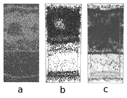
We have run molecular dynamics simulations of shear at high rates and various temperatures. We observe a dynamic transition in the mode of shear deformation, as illustrated in Fig. 1 and the Supplemental movie. Up to 900K, the deformation proceeds by dislocation motion which changes the shape of each grain. Some coarsening of the microstructure can also be seen (Supplemental Fig.1).None of these processes generate shear-band localization. Above 1400K, the mechanism is similar, until about 50% strain, at which point a two phase structure appears spanning the system. Even with a few million atoms, all the shear is concentrated in the localized non-crystalline region. Within this amorphous region, there is no ordering by layer as has been seen in smaller, single-phase simulationsWu et al. (2009) small nanocrystallites survive and move around within disordered surroundings (Supplemental Fig.2).Although there are some boundary-condition artefacts in the simulation, the central result is that at sufficiently high temperature, an amorphization mechanism dominates deformation and causes the shear to becomes localized (Fig. 1). On cooling such a region the embedded nanocrystallites grow to from a nanoscale grain structure. At even higher temperatures the shear band melts.
Our embedded-atom type potentialsHepburn and Ackland (2008); Mendelev et al. (2003) are reliable for giving a qualitative description of this type of dynamical phase transition, but cannot give a quantitative description of a real material. The most reliable way to interpret them is by proximity to melting point, in which context different MD temperatures represent different alloy-REM compositions. The key elements driving the transition are generic: temperature close to melting point; inefficiency of the dislocation mechanism to accommodate high shear; localized adiabatic heating due to poor heat conduction. These three conditions are well realized in titanium.
The practical implication of the simulations is that we have predicted that under cutting conditions this amorphization mechanism causes shear-localization in a fast-shearing band. This localization of energy release maintains a high temperature, which ultimately causes melting, associated loss of shear rigidity, and separation of the segments between shear bands. Alloys with low Ti-REM eutectic melting point should show improved machinability.
Alloys with low melting points have other drawbacks, so we attempted to design a material where the low melting point would manifest itself only in the shear band during machining (see Supplemental Materials for sample preparation details). All REMs are almost insoluble in the Ti matrix at room temperature, and form fine intragranular dispersoids during crystallization (Supplemental Fig.3). Heating the two-phase material melts only the dispersoids, so only the shear-mixed shear-band region has the reduced melting point.
Other ambient material properties (hardness, moduli etc.) are largely unchanged whereas the fatigue limit is slightly diminished (by about 10%) due to the soft, micrometer-size REM-particles (Ref Siemers et al. (2011a) and SM). At the elevated temperatures within the shear band, we expect that the REMs will become mechanically alloyed with the matrix, lowering the melting point. This will trigger the transition into the regime where amorphization becomes the deformation mechanism. We tried various Ti-based matrix materials and note that our approach was unsuccessful with alloys containing Sn, because intermetallics like La5Sn3 formed.
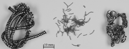
We performed orthogonal high-speed cutting and quick-stop micromachining experiments Hoffmeister and Wessels (2005); Siemers et al. (2011b); Hussain et al. (2013) which allow for subsequent analysis of chips and root-chips. In addition, we performed turning experiments with state-of-the art cutting parameters. Using cutting speeds (vc) between 5 m/s and 100 m/s we find that alloys with the lower melting-point REMs (Ce, La, Nd) produce desirable short-breaking chips with completely separated segments, while the higher melting-point REMs (Y, Er) deformed conventionally leading to unbroken but segmented chips (Fig.2). The embrittlement trend follows the eutectic temperatureMassalski (1990): the shear-band breaks for elements with Ti-REM eutectic temperature below 1400K, (Ti-Ce: 1070K, Ti-La 1070K, Ti-Nd 1230K), but compositions with higher eutectic temperatures only give segmented chips. (Ti-Er 1600K, Ti-Y 1630K).
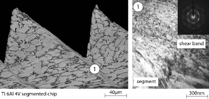
The post-recovered samples with segmented chips were investigated using optical microscopy (OM), scanning electron microscopy (FE-SEM) and transmission electron microscopy (TEM) together with selected area diffraction (SAD) within the shear band and the relatively undeformed segment material. Due to chip fragmentation only the shear bands of the standard alloy chips could be analysed by TEM. This reveals that the segmented chips show a nanocrystalline recrystallized microstructure in the shear band (Fig. 3, Supplemental Fig.6).This has been observed in low-Poission ratio alloysHao et al. (2007) but here it strongly suggests that the material in the band has been amorphized and recrystallized, as in the MD calculation. The grain size outside the shear band is similar to the material prior to machining, with some additional texture suggesting dislocation deformation.
Synchrotron X-ray diffraction (See SM) was used to confirm the hcp or bcc crystal structureHammersley et al. (1996); Toby (2005); Saksl et al. (2013), depending on alloy typeTegner et al. (2012), and the patterns enable us to detect the dispersoids, intermetallics and to confirm the absence of internal oxidation.
Focused X-ray beam patterns obtained from the shear band and surrounding areas were also collected (Supplemental Fig.5, only possible in the standard alloys) The post-machined, segmented samples have both localized shear bands and relatively undeformed material which we compare (Fig. 3). The discontinuous nature of the rings when the beam is focussed on the undeformed region shows that the grain size is large, similar to the bulk material. By contrast, the central pattern with the X-ray beam focussed on the shear band shows smooth rings show a nanocrystalline structure with grains much smaller than the beam size. This is what we expect from a rapid recrystallization of the amorphous region, and can also be discerned in the TEM.
The X-ray diffraction also confirms the structure: the former shear bands show full Bragg rings, corresponding to a nanocrystalline structure created by deformation melting and dynamic recrystallization. On the other hand, the patterns taken from the segments which have not been through the premelting transformation show Laue spots with pronounced diffuse scattering coming from large crystallites with preferred orientation Saksl et al. (2013).
In summary, we have found that under high shear rates and temperatures a transition from dislocation deformation and grain boundary sliding to shear-band amorphization occurs. As the temperature increases, the shear-banded region softens, causing the strain to become more concentrated within the band. This leads to a positive feedback as the stress becomes more localized, depositing still more energy in the shear band region. These concepts have been applied to free-machining titanium alloys using rare earth inclusions (Ce, La, Nd). The high shear and temperature mixes these insoluble metals, and if the relevant eutectic alloy has a melting point below the temperature in the shear band, cohesion is lost and the segments separate. In conventional cutting tests, only those REM-doped materials with low eutectic melting temperatures were found to have short-breaking chips.
This fracture mechanism should be generally applicable to any alloy producing segmented chips and with low enough thermal conduction that the shear band can exceed the eutectic temperature for the microsecond duration of the fracture. This opens the possibility of creating free-machining alloys of Ti, Zr, Nb, Ni, Ta, W by addition of insoluble elements with compartively low melting points. Indeed, we have also produced a free-machining nickel-base super alloy (Alloy 625) by silver addition Siemers et al. (2012).
References
- Butler and Harrowell (1995) S. Butler and P. Harrowell, J. Chem. Phys. p. 4653–4671 (1995).
- Stevens et al. (1991) M. J. Stevens, M. O. Robbins, and J. F. Belak, Phys. Rev. Lett. 66, 3004 (1991), URL http://link.aps.org/doi/10.1103/PhysRevLett.66.3004.
- Eisenmann et al. (2010) C. Eisenmann, C. Kim, J. Mattsson, and D. A. Weitz, Phys. Rev. Lett. 104, 035502 (2010).
- Wu et al. (2009) C. J. Wu, P. Soderlind, J. Glosli, and J. Klepeis, Nature Mater. p. 223 (2009).
- Joseph et al. (1999) B. Joseph, M. Picat, and F. Barbier, Eur. Phys. J. AP pp. 19–31 (1999).
- Teed (1953) P. L. Teed, Nature 172, 608 (1953).
- Aimi et al. (2004) M. F. Aimi, M. P. Rao, N. C. MacDonald, A. S. Zuruzi, and D. P. Bothman, Nature Materials 3, 103 (2004).
- Baeker (2006) M. Baeker, Journal of Materials Processing Technology 176, 117 (2006).
- Johnson and Cook (1983) G. R. Johnson and W. H. Cook, Proceedings of the 7th International Symposium on Ballistics pp. 541–547 (1983).
- Ye et al. (2003) Y. Y. Ye, R. Biswas, J. R. Morris, A. Bastawros, and A. Chandra, Nanotechnology 14, 390 (2003).
- Pei et al. (2007) Q. X. Pei, C. Lu, and H. P. Lee, Computational Materials Science 41, 177 (2007).
- Mendelev et al. (2003) M. I. Mendelev, S. Han, D. J. Srolovitz, G. J. Ackland, D. Y. Sun, and M. Asta, Philosophical magazine 83, 3977 (2003), ISSN 1478-6443.
- Hepburn and Ackland (2008) D. J. Hepburn and G. J. Ackland, Phys. Rev. B 78, 165115 (2008).
- Pinsook and Ackland (1999) U. Pinsook and G. J. Ackland, Physical Review B 59, 13642 (1999).
- Ackland (1991) G. J. Ackland, Philosophical Magazine A 71, 917 (1991).
- Ackland et al. (2011) G. J. Ackland, K. D’Mellow, S. L. Daraszewicz, D. J. Hepburn, M. Uhrin, and K. Stratford, Computer Physics Communications 182, 2587 (2011).
- Van Swygenhoven et al. (2004) H. Van Swygenhoven, P. M. Derlet, and A. G. Froseth, Nature Materials 3, 399 (2004).
- Parrinello and Rahman (1980) M. Parrinello and A. Rahman, Phys.Rev.Lett. 45, 1196 (1980).
- Gunkelmann et al. (2012) N. Gunkelmann, E. M. Bringa, K. Kang, G. J. Ackland, C. J. Ruestes, and H. M. Urbassek, Phys. Rev. B 86, 144111 (2012).
- Lane et al. (2012) P. D. Lane, G. J. Galloway, R. J. Cole, M. Caffio, R. Schaub, and G. J. Ackland, Phys. Rev. B 85, 094111 (2012).
- Lewandowski and Greer (2006) J. J. Lewandowski and A. L. Greer, Nature Materials 5, 15 (2006).
- Siemers et al. (2011a) C. Siemers, F. Brunke, M. Stache, J. Laukart, B. Zahra, J. Roesler, P. Rokicki, and K. Saksl, Proceedings of the 12th World Conference on Titanium (Ti-2011), Beijing, China, June 2011 pp. 883–887 (2011a).
- Hoffmeister and Wessels (2005) H. W. Hoffmeister and T. Wessels, Hochgeschwindigkeitsspanen pp. 470–492 (2005).
- Siemers et al. (2011b) C. Siemers, J. Laukart, B. Zahra, J. Roesler, Z. Spotz, and K. Saksl, Materials Science Forum 690, 262 (2011b).
- Hussain et al. (2013) M. S. Hussain, C. Siemers, and J. Roesler, Journal of Materials and Manufacturing Processes 28, 545 (2013).
- Massalski (1990) T. B. Massalski, Binary Alloy Phase Diagrams, vol. 1 (American Society for Metals, Metals Park, OH, 1990).
- Hao et al. (2007) Y. L. Hao, S. J. Li, B. B. Sun, M. L. Sui, and R. Yang, Phys. Rev. Lett. 98, 216405 (2007), URL http://link.aps.org/doi/10.1103/PhysRevLett.98.216405.
- Saksl et al. (2013) K. Saksl, P. Rokicki, C. Siemers, D. Ostroushko, J. Bednarcik, and U. Ruett, Journal of Alloys and Compounds 581, 579 (2013).
- Hammersley et al. (1996) A. Hammersley, S. O. Svensson, M. Hanfland, A. N. Fitch, and D. Hausermann, High Pressure Research 14(4-5), 235 (1996).
- Toby (2005) B. H. Toby, Journal of Applied Crystallography 38, 1040 (2005).
- Tegner et al. (2012) B. E. Tegner, L. Zhu, and G. J. Ackland, Phys.Rev.B 85, 214106 (2012).
- Siemers et al. (2012) C. Siemers, F. Brunke, J. Laukart, M. S. Hussain, J. Roesler, P. Rokicki, K. Saksl, and B. Zahra, Proceedings of the COM2012, Niagara Falls, Canada, October 2012 pp. 281–292 (2012).
- Li (2003) J. Li, Modelling Simul. Mater. Sci. Eng. 11, 173 (2003).
Acknowledgements This work was supported by a research grant MAMINA PITN-GA-2008-211536 from the EU-FP7 programme. Beamtime at DORIS, beamline BW5, and PETRA III synchrotron, beamline P07, is gratefully acknowledged. We would like to thank M. Girelli, A. Gente and B. Zahra for the machining experiments. The work on Ti 6Al 4V alloy has been supported by the Arbeitsgemeinschaft industrieller Forschungsvereinigungen (AiF), Project Number IGF 253 ZN.
All authors contributed equally to the research. CH, SK and GJA designed and performed the calculations. CS and DM performed the sample preparation, the TEM and XRD experiments. GJA and CS wrote the paper, with assistance from CH, DM and SK.