X-ray flares from dense shells formed in gamma-ray burst explosions
Abstract
Bright X-ray flares are routinely detected by the Swift satellite during the early afterglow of gamma-ray bursts, when the explosion ejecta drives a blast wave into the external medium. We suggest that the flares are produced as the reverse shock propagates into the tail of the ejecta. The ejecta is expected to contain a few dense shells formed at an earlier stage of the explosion. We show an example of how such dense shells form and describe how the reverse shock interacts with them. A new reflected shock is generated in this interaction, which produces a short-lived X-ray flare. The model provides a natural explanation for the main observed features of the X-ray flares — the fast rise, the steep power-law decline, and the characteristic peak duration .
keywords:
Gamma rays bursts: general; Radiation mechanisms: non-thermal; Shock waves.1 Introduction
About 30% of GRBs show X-ray flares during their early afterglow (e.g. Burrows et al. 2005b; Falcone et al. 2007; Chincarini et al. 2010). Sometimes they are accompanied by significant flux increase in the optical band (e.g. Li et al. 2012). The X-ray flares are characterized by a fast rise of luminosity (typically by a factor ) to a sharp peak followed by a power-law decay (Chincarini et al., 2007). The ratio of the characteristic temporal width of the peak to its time of occurrence since the beginning of the GRB is typically . At the end of the flare, the X-ray flux resumes the underlying smooth decay of the early afterglow, with no apparent flux increment left.
Besides the X-ray flares, the early afterglow shows other puzzling features, such as plateaus and sudden steep decrease in the observed luminosity. These features are not explained by the standard forward shock model (Meszaros & Rees, 1997; Sari et al., 1998), and it was proposed that the observed afterglow is produced by a long-lived reverse shock inside the GRB ejecta (Uhm & Beloborodov, 2007; Genet et al., 2007). The dynamics and emission of the reverse shock are particularly sensitive to the structure of the ejecta (the distribution of its Lorentz factor, density, and magnetic fields) which may explain the rich phenomenology of the early afterglow (Hascoët et al., 2011, 2012; Uhm et al., 2012; Hascoët et al., 2014b).
The fast rise and relatively short duration of the X-ray flares motivated several authors to invoke late activity of the central engine and associate the flares with the jet produced by this activity — a scaled-down version of the prompt GRB emission (e.g. Burrows et al. 2005a; Fan & Wei 2005; Zhang et al. 2006). This possibility requires a mechanism that keeps the central engine active for about one day, as some flares are observed as late as a day after the GRB explosion. It also requires the engine to be variable in a special way on a timescale , in contrast to the much faster, multi-peak variability observed during the prompt GRB.
This Letter proposes an alternative possibility that the flares are produced by the long-lived reverse shock when it crosses the tail of the GRB ejecta. Our model does not require a long-lived central engine; it requires that the Lorentz factor in the end of the GRB explosion is significantly reduced, from to , which leads to the formation of an extended tail (e.g. Uhm & Beloborodov 2007; Genet et al. 2007). As described in Section 2, dense shells are expected to form in the tail of the expanding ejecta before the passage of the reverse shock. In Section 3 we estimate the bolometric light-curve of emission produced by the encounter of the reverse shock with the dense shell, and find that it resembles the observed X-ray flares. Comparison of the model with observations and future possible ways of its development are discussed in Section 5.
2 Dense shells after internal shocks
The observed variability of GRB emission (Fishman & Meegan, 1995; Beloborodov et al., 2000; Guidorzi et al., 2012) suggests that the Lorentz factor of the relativistic ejecta fluctuates in a broad range of timescales, from a few milliseconds to several minutes. In the expanding outflow, regions where the radial gradient of Lorentz factor is negative (i.e. where is decreasing outwards) are progressively compressed. If the ejecta is not magnetically dominated, internal shocks eventually form and propagate. The internal shocks can impact the prompt -ray emission mainly in two ways: (i) in the subphotospheric (optically thick) region, shock heating can offset the adiabatic cooling of radiation and change its spectrum from thermal to the observed Band-type shape through the Comptonization process and additional synchrotron emission (Mészáros & Rees, 2000; Pe’er et al., 2006; Beloborodov, 2010; Vurm et al., 2011); (ii) outside the photosphere, shocks can continue to produce synchrotron emission in the gamma-ray band if they efficiently accelerate particles (Rees & Meszaros, 1994; Kobayashi et al., 1997; Daigne & Mochkovitch, 1998).
The outflow is likely initially inhomogeneous, and internal shocks can amplify the density variations, especially if the shocks are radiatively efficient. More importantly, the outflow tends to develop a few massive dense shells long after the shocks. At time when the internal shock phase ends, the fluctuations of Lorentz factor have been damped and acquires a monotonic radial profile. Its slope is significantly inhomogeneous, as illustrated below by a hydrodynamical simulation. The subsequent ballistic expansion of the outflow at generates a large contrast in density, as can be seen from the following estimate.
Consider a shell of width with the Lorentz factor variation across the shell . As the shell expands ballistically, its width evolves as
| (1) |
where is the shell width at . The relevant at the end of the internal shock phase corresponds to the longest variability timescale observed in the burst, , which is comparable to the burst duration, e.g. s. In contrast, the time given to ballistic expansion before the reverse shock crosses the outflow in our model is associated with the observed time of the X-ray flares, s.
The large ratio implies that should strongly affect the density structure of the outflow. The parts of the outflow with will become much thicker than the parts with , which will form dense shells. The corresponding density contrast is roughly given by
| (2) |
An important feature of the post-internal-shock flows is the presence of a few “plateaus” in the profile of or where is the Lagrangian mass coordinate in the flow. These plateaus contain a large mass and eventually form dense massive shells because of their small . We have observed and studied this effect in outflows with various initial using detailed hydrodynamical simulations. We found that that the plateaus typically have a small of a few per cent, even in the case of adiabatic shocks (an example is shown in Figure 1). The simulations have been performed using a one-dimensional (spherically symmetric) hydrodynamic code with a second-order HLLC approximate Riemann solver (Mignone & Bodo, 2005) on a moving mesh (Duffell & MacFadyen, 2011).

|
Similar (but exactly flat) plateaus are produced by simplified simulations in which the outflow is represented by a large number of discrete shells that interact by direct collisions (Daigne & Mochkovitch, 1998). In this model, the ejecta is assumed to be cold and all pressure waves are neglected. This simplification is not crucial as it gives results similar to the detailed hydrodynamical simulations (cf. Daigne & Mochkovitch 2000). Below we use the simplified model and extend the simulation to include the external blast wave and the reverse shock propagation through the outflow.
3 Flares: a simplified model
We used the simplified hydrodynamical simulations to follow the reverse shock (RS) propagation through the outflow and its interaction with the dense shells. A sample model is shown in Figure 2. In this example, the explosion is assumed to produce an outflow of variable Lorentz factor distribution and duration s. The injected kinetic power erg s-1 is assumed to be constant. Figure 2 shows how the initial distribution of is changed after the internal shocks. Most of the outflow mass concentrates into three shells with Lorentz factors , and carrying about 10, 20, and 40 per cent of the total mass. The last 30 per cent of the outflow have not been affected by internal shocks.


|
We followed the outflow to much larger radii where the RS eventually crosses all three shells. The dynamics of the reverse shock depends on the external density. We have calculated two cases: a uniform external medium and a wind-like medium , where is a constant which depends on the mass-loss rate of the GRB progenitor. Its typical range for galactic Wolf-Rayet stars is (Crowther, 2007). Recent modelling of optical and GeV flashes in GRBs suggest that is typical for GRB progenitors (Hascoët et al. 2014a; Hascoët, Vurm & Beloborodov, to be submitted).
3.1 Bolometric light curve
The simulation gives the power dissipated in the RS and its bolometric luminosity with two assumptions: (i) that a fraction of the dissipated energy is injected in shock-accelerated electrons, and (ii) that these electrons promptly radiate their energy (“fast-cooling” regime). To find the bolometric light curve received by a distant observer we transform the emission from the flow frame to the observer frame and take into account the spherical curvature of the emitting shells. The radiation received by the observer from the RS is shown in Figure 2. In this figure, we also included the prompt radiation produced by the internal shocks, assuming the same .
When the reverse shock goes through the dense shells there is a sudden rise of dissipated power producing a flare in the light curve. The immediate rise of luminosity to the peak of the flare in Figure 2 is an artefact of the simplified model, which does not resolve the propagation of the reverse shock through the dense shell. An accurate hydrodynamical model would give a slower but still a steep rise; it is discussed and estimated in Section 4 below.
In our example with three dense shells, two flares are produced; the crossing of the first shell (at ) corresponds to the initial rise of dissipated power from the reverse shock. Using the approximate expression for the flare radius , one can estimate the observed time of the flare,
| (3) | |||||
| (4) |
Here is the Lorentz factor of the massive shell (), is the kinetic energy of the ejecta that has already crossed the reverse shock ( erg), is the density of the uniform medium in cm-3 and is the density parameter of the wind medium in units of . One can see that the flare can be significantly delayed and this delay is sensitive to the Lorentz factor of the massive shell.
We also observe that the flares produced by this mechanism share two key features with the observed X-ray flares: (i) after the flare the light curve returns to the pre-flare decaying afterglow and (ii) the flare duration is proportional to its time of occurrence .
The simulation shown in Figure 2 assumes fast cooling at all times, which gives a constant radiative efficiency equal to . The flux enhancement during the flare can be even higher if before and after the flare the emission is in the slow-cooling regime. Then the radiative efficiency can be significantly increased during the flare.
3.2 Effect of anisotropic emission
In the simplest model, which assumes isotropic emission in the fluid frame, the characteristic temporal width of the flare is where
| (5) |
Then the ratio is close to unity, greater than the typical observed ratio .
Significant anisotropy is, however, expected and supported by the fast luminosity variations observed in GRB afterglows (Beloborodov et al., 2011). The effect of anisotropy on the flare light curve is demonstrated by the following simple model.
For the moment, let us picture the encounter of the reverse shock with the dense shell as an instantaneous flash of energy at a radius . The bolometric light curve received from such a flash is given by (Beloborodov et al., 2011),
| (6) |
where
| (7) |
is the angle with respect to the radial direction in the fluid frame, and describes the angular distribution of emission; for isotropic emission . The magnetic field in GRB shocks is in the shock plane, and their synchrotron radiation is anisotropic even when the emitting electrons are isotropic; in this case . Anisotropy of the electron distribution can further enhance the anisotropy of the emitted radiation, which significantly shortens the duration of the flare (see Figure 3 in Beloborodov et al. 2011), leading to a characteristic duration . The shorter duration corresponds to a steeper decay of luminosity after the peak, with initial temporal index .
4 Shock reflection from the dense shell
|
In the simplified model of Section 3, the RS crossing of the thin dense shell instantaneously dissipates part of the shell kinetic energy, and the observed light curve of the flash is determined by the curvature effect. In this section, we describe a more realistic picture of the RS interaction with the dense shell. We also estimate the timescales for the rise and duration of the dissipation event.
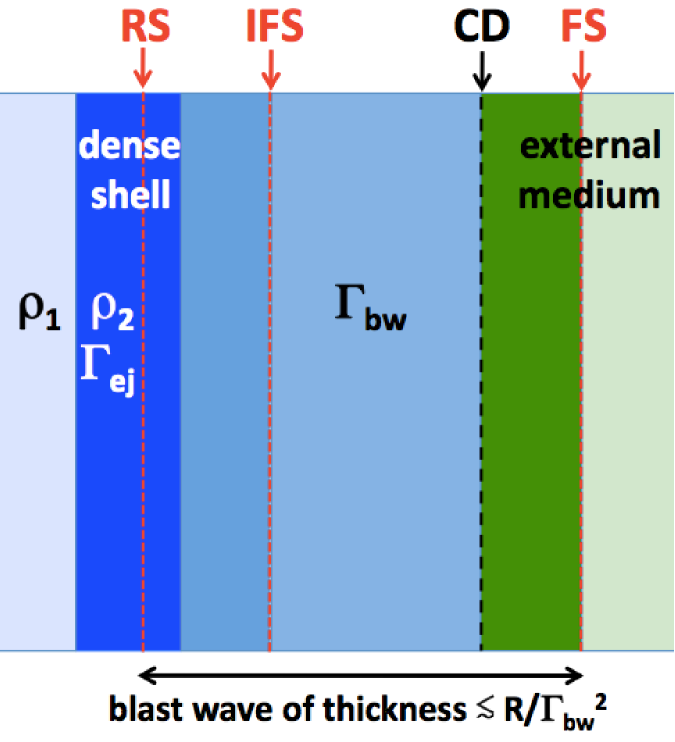
Two main effects should be taken into account: (i) The RS is greatly slowed down as it enters the dense gas, and it takes a finite time (estimated below) for the RS to cross the shell. (ii) The RS by itself does not efficiently decelerate the shell. The shell continues to plow through the ejecta that was previously accumulated in the blast wave. This ploughing launches a new internal shock inside the blast wave (Figure 3). Effectively, the RS splits in two when it enters the dense shell. One (slow) shock continues to propagate into the dense shell and the other (fast) shock is reflected and launched back into the blast wave material. The fast shock dissipates most of the kinetic energy of the massive shell measured in the rest-frame of the blast wave. Below we call it ‘internal forward shock’ (IFS). It is the IFS that emits the X-ray flare.
The velocity of RS propagation through the dense shell, , may be estimated using the approximate pressure balance between the RS and IFS. Let be the proper density of the shell just before it is reached by the RS. Assuming that the shell is cold and weakly magnetized, its pressure behind the RS jumps to
| (8) |
Now, let us estimate the pressure behind the IFS, . The dense shell acts like a wall and the Lorentz factor downstream of the IFS is almost equal to the shell Lorentz factor . The relative Lorentz factor of the upstream and downstream is
| (9) |
where is the Lorentz factor of the blast-wave material upstream of the IFS, and we have used and . Gas pressure may be written as (Beloborodov & Uhm, 2006), where is the density and is the energy per unit rest mass. The gas in the downstream of IFS has been shocked twice: first by the RS and then by the IFS, both times with the same relative Lorentz factor . Therefore, and , where is the outflow proper density prior to the crossing by the RS and IFS. In the estimate for we used the compression factor of for a strong adiabatic shock. This gives
| (10) |
The approximate pressure balance gives an estimate for ,
| (11) |
Using the obtained , we estimate the time it takes the RS to cross the dense shell, . The shell thickness is comparable to
| (12) |
where is the blast wave thickness, and is the ratio between the mass of the incoming dense shell, , and the outflow mass already accumulated in the blast wave, . Then we find
| (13) |
Typical expected implies a short .
The shell Lorentz factor is reduced from to when it sweeps up the rest-mass
| (14) |
where we took into account that the gas ahead of the shell has been heated by the RS, and so its inertial mass is increased by the factor of . Assuming a relativistic IFS speed , this gives the following estimate for the observed duration of the shell deceleration:
| (15) |
The IFS may be mildly relativistic, , if the flares occur long after the formation of the ballistic outflow (). If the blast wave dynamics between the flares is approximated as self-similar, one finds and in the case of the wind and uniform external medium respectively.
The time is associated with the rise of the energy injection event and determines its duration. The above results give typical . For short the observed duration of the flare will be determined by the curvature (and anisotropy) effects, as described in Section 3.2. Here we note an additional effect which reduces the observed duration of the flare. While the pre-flare afterglow is emitted by gas moving with , the flare is emitted by gas moving with (the gas behind the IFS). Therefore, even without the anisotropy effect, the curvature timescale for the flare is compressed by the factor of .
5 Conclusions
This Letter suggests that GRB outflows naturally develop a few dense shells with relatively low Lorentz factors, which leads to a new explanation for the X-ray flares. The dense shells give sudden energy injections to the GRB afterglow. We examined the dynamics of the injection event and showed that it generates a new internal shock behind the blast wave, which produces a short-lived flare. This mechanism provides a natural explanation for the fast rise of the X-ray flares and their observed duration .
The proposed scenario assumes two radiative properties of the shock: (i) a fraction of the shock energy is transferred to non-thermal accelerated electrons capable of emitting synchrotron X-rays, and (ii) the electrons radiate X-rays in the fast cooling regime. Detailed modeling of hydrodynamics and radiative properties of the flares are deferred to a future work. As described in Section 4, the flare is emitted by gas that has been shocked twice and has high density and pressure. This gas can also possess strong magnetic fields and can radiate more efficiently compared with the pre-flare afterglow. This will help to satisfy the conditions (i) and (ii).
Acknowledgments
It is a pleasure to thank H. van Eerten and A. I. MacFadyen for useful discussions on hydrodynamics simulations. This work has been partially supported by the Programme National Hautes Energie (PNHE) and the French Space Agency (CNES) . AMB was supported by NSF grant AST-1412485 and NASA Swift Cycle 10 grant NNX14AI94G.
References
- Beloborodov (2010) Beloborodov, A. M. 2010, MNRAS, 407, 1033
- Beloborodov et al. (2011) Beloborodov, A. M., Daigne, F., Mochkovitch, R., & Uhm, Z. L. 2011, MNRAS, 410, 2422
- Beloborodov et al. (2000) Beloborodov, A. M., Stern, B. E., & Svensson, R. 2000, ApJ, 535, 158
- Beloborodov & Uhm (2006) Beloborodov, A. M., & Uhm, Z. L. 2006, ApJL, 651, L1
- Burrows et al. (2005a) Burrows, D. N., Romano, P., Falcone, A., et al. 2005a, Science, 309, 1833
- Burrows et al. (2005b) Burrows, D. N., Hill, J. E., Nousek, J. A., et al. 2005b, Space Science Reviews, 120, 165
- Chincarini et al. (2007) Chincarini, G., Moretti, A., Romano, P., et al. 2007, ApJ, 671, 1903
- Chincarini et al. (2010) Chincarini, G., Mao, J., Margutti, R., et al. 2010, MNRAS, 406, 2113
- Crowther (2007) Crowther, P. A. 2007, Annual Review of Astronomy and Astrophysics, 45, 177
- Daigne & Mochkovitch (1998) Daigne, F., & Mochkovitch, R. 1998, MNRAS, 296, 275
- Duffell & MacFadyen (2011) Duffell, P. C., & MacFadyen, A. I. 2011, ApJS, 197, 15
- Falcone et al. (2007) Falcone, A. D., Morris, D., Racusin, J., et al. 2007, ApJ, 671, 1921
- Fan & Wei (2005) Fan, Y. Z., & Wei, D. M. 2005, MNRAS, 364, L42
- Fishman & Meegan (1995) Fishman, G. J., & Meegan, C. A. 1995, Annual Review of Astronomy and Astrophysics, 33, 415
- Genet et al. (2007) Genet, F., Daigne, F., & Mochkovitch, R. 2007, MNRAS, 381, 732
- Guidorzi et al. (2012) Guidorzi, C., Margutti, R., Amati, L., et al. 2012, MNRAS, 422, 1785
- Hascoët et al. (2014a) Hascoët, R., Beloborodov, A. M., Daigne, F., & Mochkovitch, R. 2014a, ApJ, 782, 5
- Hascoët et al. (2012) Hascoët, R., Daigne, F., & Mochkovitch, R. 2012, A&A, 541, A88
- Hascoët et al. (2014b) —. 2014b, MNRAS, 442, 20
- Hascoët et al. (2011) Hascoët, R., Uhm, Z. L., Mochkovitch, R., & Daigne, F. 2011, A&A, 534, A104
- Kobayashi et al. (1997) Kobayashi, S., Piran, T., & Sari, R. 1997, ApJ, 490, 92
- Li et al. (2012) Li, L., Liang, E.-W., Tang, Q.-W., et al. 2012, ApJ, 758, 27
- Meszaros & Rees (1997) Meszaros, P., & Rees, M. J. 1997, ApJ, 476, 232
- Mészáros & Rees (2000) Mészáros, P., & Rees, M. J. 2000, ApJ, 530, 292
- Mignone & Bodo (2005) Mignone, A., & Bodo, G. 2005, MNRAS, 364, 126
- Pe’er et al. (2006) Pe’er, A., Mészáros, P., & Rees, M. J. 2006, ApJ, 642, 995
- Rees & Meszaros (1994) Rees, M. J., & Meszaros, P. 1994, ApJL, 430, L93
- Sari et al. (1998) Sari, R., Piran, T., & Narayan, R. 1998, ApJL, 497, L17
- Uhm & Beloborodov (2007) Uhm, Z. L., & Beloborodov, A. M. 2007, ApJL, 665, L93
- Uhm et al. (2012) Uhm, Z. L., Zhang, B., Hascoët, R., et al. 2012, ApJ, 761, 147
- Vurm et al. (2011) Vurm, I., Beloborodov, A. M., & Poutanen, J. 2011, ApJ, 738, 77
- Zhang et al. (2006) Zhang, B., Fan, Y. Z., Dyks, J., et al. 2006, ApJ, 642, 354