Experimental investigation of the elastic enhancement factor
in a transient region between regular and chaotic dynamics
Abstract
We present the results of an experimental study of the elastic enhancement factor for a microwave rectangular cavity simulating a two-dimensional quantum billiard in a transient region between regular and chaotic dynamics. The cavity was coupled to a vector network analyzer via two microwave antennas. The departure of the system from the integrable one due to presence of antennas acting as scatterers is characterised by the parameter of chaoticity . The experimental results for the rectangular cavity are compared with the ones obtained for a microwave rough cavity simulating a chaotic quantum billiard. The experimental results were obtained for the frequency range GHz and moderate absorption strength . We show that the elastic enhancement factor for the rectangular cavity lies below the theoretical value predicted for integrable systems and it is significantly higher than the one obtained for the rough cavity. The results obtained for the microwave rough cavity are smaller than the ones obtained within the framework of Random Matrix Theory and lie between them and the ones predicted within a recently introduced model of the two-channel coupling (V. Sokolov and O. Zhirov, arXiv:1411.6211v2[nucl-th], 12 Dec 2014).
pacs:
05.45.Mt,03.65.NkI Introduction
The elastic enhancement factor was introduced more than 50 years ago by Moldauer Moldauer1961 and since then it has been frequently considered in nuclear physics Kretschmer1978 ; Verbaarschot1986 ; Kharkov2013 and in other fields Fyodorov2005 ; Savin2006 . The elastic enhancement factor is the ratio of variances of diagonal elements of the two-port scattering matrix to off-diagonal elements of this matrix Fyodorov2005 ; Savin2006 ; Kharkov2013 . From the experimental point of view the elastic enhancement factor , where or is the symmetry index for systems with preserved and broken time reversal symmetry, respectively, is especially interesting because it can be used to study realistic open systems also in the presence of absorption. The properties of the elastic enhancement factor have been studied in several precisely controllable systems such as microwave cavities Fiachetti2003 ; Zheng2006 ; Dietz2010 ; Anlage2013 and networks Lawniczak2010 ; Lawniczak2011 ; Lawniczak2012 . The conjecture on the universality of the ratio of variances of the scattering elements in electromagnetic fields in the mode-stirred reverberating chambers (time reversal invariant system) was put forward by Fiachetti and Michelson Fiachetti2003 . The universality of the elastic enhancement factor has been also tested in the wave scattering experiments with microwave cavities simulating chaotic quantum billiards Zheng2006 ; Dietz2010 in the presence of absorption. Dietz et al. Dietz2010 have studied the universality of the elastic enhancement factor with microwave cavities in the case of preserved and partially broken time reversal symmetries. Quite recently an extensive study of the elastic enhancement factor has been published by Yeh et al. Anlage2013 . In that paper the authors were also able to study the elastic enhancement factor for microwave cavities with time reversal symmetry in a low absorption regime. The reciprocal quantity was considered theoretically and measured as a function of frequency for a chaotic microwave cavity with time reversal symmetry Zheng2006 ; Anlage2013 .
The elastic enhancement factor has been also studied for microwave irregular networks Hul2004 ; Hul2012 simulating quantum graphs with preserved and broken time reversal symmetry in the presence of moderate and large absorption strength defined as follows: , where is the average resonance width and is the mean level spacing Fyodorov2005 ; Savin2006 , Lawniczak2010 ; Lawniczak2011 ; Lawniczak2012 . Microscopically, the absorption strength can be modeled by means of a huge number of open, coupled to continuum channels ”c”, where and stands for the average -matrix Savin2006 . The recent paper of Kharkov and Sokolov Kharkov2013 has shown that the elastic enhancement factor of open systems with a transient from the regular to chaotic internal dynamics depends on both the parameter of chaoticity and the openness . The openness is formally described by the same formula as the absorption strength Kharkov2013 .
It is important to point out that the elastic enhancement factor for the systems with absorption, in a transient region between regular and chaotic dynamics, has not been studied experimentally yet. In this paper we present the results of the experimental study of the elastic enhancement factor Fyodorov2005 ; Savin2006 for microwave rectangular and rough cavities, coupled to the vector network analyzer through antennas, simulating respectively, partially chaotic and chaotic two-dimensional (2D) quantum billiards with preserved time reversal symmetry () in the presence of moderate absorption.
The elastic enhancement factor is defined by the relationship Fyodorov2005 ; Savin2006
| (1) |
where is the variance of the scattering matrix element of the two-port scattering matrix
| (2) |
For small and intermediate values of the parameter the elastic enhancement factor might depend both on the parameter and on the coupling to the system Zheng2006 . However, for large absorption strength the elastic enhancement factor can be approximated by the formula: Fyodorov2005 ; Savin2006 ; Zheng2006 . Fiachetti Fiachetti2008 showed that in the case of the stochastic environment which can be characterized by a statistically isotropic scattering matrix the elastic enhancement factor should have the universal value . Recently, the two-channel problem (e.g., an experimental system with two ports ”a” and ”b”) with internal absorption and time reversal symmetry has been numerically considered by Sokolov and Zhirov Sokolov2014 . It has been shown that for the equivalent channels ”a” and ”b” with the transmission coefficients , , the elastic enhancement factor depends both on the transmission coefficient and internal absorption and can take, respectively, the values between 3 and 2. Thereafter, we will use the abbreviation .
II Microwave cavities simulating quantum billiards
In the experiment we used a microwave rectangular cavity to simulate a two dimensional (2D) billiard in a transient region between regular and chaotic dynamics. A quantum chaotic billiard was simulating by a rough microwave cavity. If the excitation frequency is below , where is the speed of light in the vacuum and is the height of the cavity, only the transverse magnetic mode can be excited inside the cavity. Then, the analogy between microwave flat cavities and quantum billiards is based upon the equivalency of the Helmholtz equation describing the microwave cavities and the Schrödinger equation describing the quantum systems Stockmann1990 ; Blumel .
Absorption of the cavities can either be changed by changing the frequency range of the measurements, or more effectively, by the application of microwave absorbers. In this paper we are only interested in moderate absorption, for which Fyodorov2005 ; Savin2006 ; Zheng2006 and which can be controlled by the choice of the microwave frequency range.
III Experimental setup
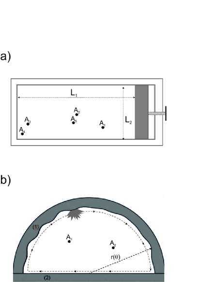
Figure 1(a) shows the scheme of the rectangular microwave cavity which was used for measuring of the two-port scattering matrix . The scattering matrix of the cavity was measured in the frequency window: 16–18.5 GHz. The vector network analyzer Agilent E8364B was connected through the HP 85133-616 and HP 85133-617 flexible microwave cables to the two microwave antennas which were introduced inside the cavity (holes , , , , in Figure 1(a)). The antennas wires (diameter 0.9 mm) were protruded 3 mm into the cavity. The measurements were completed for 10 different positions of the antennas. The width of the rectangular cavity was cm. Different realizations of the cavity were created by the change of its length from to 36.5 cm in 25 steps of 0.2 cm length.
Figure 1(b) shows the scheme of the rough microwave cavity Hul2005 . The cavity is composed of the two side wall segments. The segment (1) is described by the function , where the mean radius =20.0 cm, , and . The amplitudes and the phases are uniformly distributed on [0.084,0.091] cm and [0,2], respectively.
Both, the rectangular and rough cavities had the same height mm, so that GHz.
Also in the case of the rough cavity the two-port scattering matrix was measured in the frequency range 16–18.5 GHz. The 3 mm long antennas were introduced inside the cavity trough the holes and . In order to create different realizations of the rough cavity a metallic perturber with the area cm2 and the perimeter cm (see panel (b)) was moved inside the cavity along the sidewalls using an external magnet. The linear size of the perturber cm was more than 2.5 times bigger than the microwave wavelength at 16 GHz.
IV The nearest neighbor spacing distributions
Properties of microwave cavities were investigated using the nearest neighbor spacing distribution . The distribution for the microwave rectangular cavity obtained for the frequency range GHz is shown in Figure 2(a) (bars). The distribution was averaged over 30 microwave cavity configurations. In this way 2760 eigenfrequencies of the cavity were used in the calculations of the distribution .
Figure 2(a) shows that in spite of using short microwave antennas the experimental distribution departures from the Poisson distribution (broken line) which is characteristic for classically integrable systems. The distribution is also different from the theoretical prediction for Gaussian Orthogonal Ensemble (GOE) in RMT (full line) characteristic for chaotic systems with time reversal symmetry, showing the transition between integrability and chaos. For it is higher than the one for GOE in RMT, however, for it is closer to the Poisson distribution. This behavior is different than the one investigated by Robnik and Veble Robnik1998 for irrational and rational rectangles where huge fluctuations and the departure of the distribution from the Poisson one were reported for very small .
The results obtained for the microwave rectangular cavity should be contrasted with the ones obtained for the nearest neighbor spacing distribution for the rough cavity (bars in Figure 2(b)) which shows much better agreement with the theoretical prediction for GOE in RMT (full line). In the case of the rough cavity the distribution was calculated on the basis of 3554 cavity eigenfrequencies. Some small discrepancies in the experimental from the RMT prediction for are possibly connected with either some unresolved resonances or fingerprints of nonuniversal behavior of the rough cavity. Similar discrepancies in the nearest neighbor spacing distribution for are also visible in the experimental results presented in the paper by Poli et al. Poli2012 . Typical spectra of the rectangular cavity in the frequency range 16-17 GHz and the rough cavity in the frequency range 8-9 GHz are shown in Figure 3(a) and Figure 3(b), respectively.
V Experimental and numerical results for the elastic enhancement factor
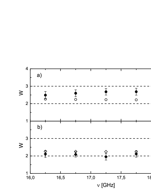
In Figure 4(a) the elastic enhancement factor of the two-port scattering matrix of the microwave rectangular cavity is shown in a function of microwave frequency GHz (full circles). Due to significant fluctuations of the enhancement factor the experimental points were obtained by averaging of over 250 different realizations of the cavity length and the antennas positions in the frequency window , where GHz. The two black broken lines and show, respectively, the RMT limits for very strong and very low absorption.
The parameter for the microwave rectangular cavities depends on microwave frequency and was changed from 5.2 to 7.4 with the increase of frequency from 16 to 18.5 GHz.
According to Kharkov and Sokolov Kharkov2013 the elastic enhancement factor of the two-port scattering matrix evaluated within the framework of RMT can be expressed by
| (3) |
where is the spectral form factor. The parameter of chaoticity changes from for classically integrable systems to for chaotic systems. It is important to note that in the transition region the spectral form factor is currently known only for systems with broken time-reversal symmetry. For integrable systems with time reversal symmetry which immediately leads to .
Figure 4(a) shows that the elastic enhancement factor of the two-port scattering matrix of the rectangular cavity is below the theoretical value . This result together with the complementary one for the experimental distribution (see Figure 2(a)) strongly suggests that the system simulated by the two-port microwave rectangular cavity due to scattering on the antennas departures from the integrable one. This phenomenon was predicted by Seba Seba1990 and then thoroughly analyzed by Tudorovskiy et al. Tudorovskiy2010 . The influence of antennas on the widths of resonances in a two-dimensional rectangular microwave cavity, in much lower than investigated in this paper frequency range from below of 1 GHz to 5.5 GHz, was studied by Barthélemy et al. Barthelemy2005 . In this experiment relatively short, 2 mm long, antennas were used. To give an idea about the antennas performance, 3 mm long antennas used is our experiment were characterized in the frequency range 16-18.5 GHz by the antenna coupling . In the frequency range 4.5-5.5 GHz, which was considered in Barthelemy2005 , the same antennas were characterized by much smaller antenna coupling .
In order to estimate the chaoticity parameter for such a system we reconstructed the nearest neighbor spacing distribution shown in Figure 2(a) using the random matrix Potter-Rosenzweig model described in Leyvraz1991 , where the matrix is defined as follows
| (4) |
where denotes a symmetric matrix which belongs to GOE matrices. is the transition parameter. The off-diagonal elements are independently Gaussian distributed with the same variance and the mean zero. The diagonal elements are independently distributed with the variance .
For the matrices of the size we found out that the parameter can be approximated by . The fit of the numerical nearest neighbor spacing distribution , calculated on the basis of 100 realizations of matrices, to the experimental one yields the chaoticity parameter . The inset in Figure 2(a) shows the numerically reconstructed nearest neighbor spacing distribution . Unfortunately, even knowing the chaoticity parameter we are not able to compare our experimental results with the theoretical ones since the explicit form of the spectral form factor is not known. Though the paper Kharkov2013 suggests that the behaviour of the enhancement factor for systems with time reversal symmetry should be similar to the one for systems with broken time reversal symmetry, this remains to be proven yet. Just for completeness of the presentation in Figure 4(a) we also show the RMT results predicted by the equation (3) (empty cirles) with the spectral form factor defined by the equation (6).
In Figure 4(b) the elastic enhancement factor of the two-port scattering matrix of the microwave rough cavity simulating a quantum chaotic system is shown (full black rhombi) in a function of microwave frequency GHz. The results were averaged over 105 different perturber positions in the frequency window GHz. It is important to note that the theoretical and experimental investigations of rough billiards (cavities) Fram1997 ; Hlushchuk2001 ; Savytskyy2004 showed that for lower energies (frequencies) there exist regimes of localization and Wigner ergodicity, and only for higher energies (frequencies) billiards (cavities) become fully chaotic. This fully chaotic regime is called the regime of Shnirelman ergodicity. For the rough cavity used in the experiment the regime of Shnirelman ergodicity extends for GHz. The presence of the perturber causes that even for lower frequencies GHz the nearest neighbor spacing distribution is close to the theoretical prediction for GOE in RMT.
The parameter was estimated by adjusting the theoretical mean reflection coefficients parameterized by the parameters
| (5) |
to the experimental ones obtained after eliminating the direct processes Anlage2006 ; Lawniczak2008 . The index denotes the port or . In the calculations of we used the analytic expression for the distribution of the reflection coefficient given in Savin2005 . We found out that using the same antennas, 3 mm long, as in the case of the rectangular cavity, the value of the parameter was changed from 5.3 to 6.8 with the increase of microwave frequency from 16 GHz to 18.5 GHz, respectively. Taking into account that the microwave antennas act as single scattering channels the absorption strength can be expressed as a sum of the transmission coefficients: , where represents internal absorption of the cavity Dietz2010 . The values of the absorption strength and the transmissions coefficients , , and are shown in Table 1.
Figure 4(b) shows that the experimental results obtained for the rough cavity are below the theoretical ones predicted for by the equation (3) within the framework of RMT (empty rhombi). For chaotic systems () with the symmetry index the spectral form factor in the equation (3) has the form Fyodorov2005 ; Savin2006 :
| (6) |
where is the Heaviside step function.
It is important to point out that the recent numerical results presented in Sokolov2014 for the two-channel problem with absorption give better agreement with the experimental ones. In the case of the two equivalent channels with and the internal absorption the theory predicts to be between 2.08 and 2.03 (see Figure 5 in Sokolov2014 ). In the experiment the internal absorption was larger than the ones considered in the theoretical calculations therefore one should expect even smaller theoretical values of the elastic enhancement factor . For comparison, the experimental elastic enhancement factor is scattered between 2.1 and 1.95.
VI Conclusions
The elastic enhancement factor was experimentally studied for microwave rectangular and rough cavities simulating partially chaotic, characterised by the transient parameter , and chaotic two-dimensional quantum billiards, respectively. Both systems were characterized by similar, moderate absorption strengths, and , respectively. We show that the results obtained for the rectangular cavity lie below the theoretical prediction for integrable systems , however, they are significantly higher than the ones obtained for the microwave rough cavity. The results obtained for the microwave rough cavity are smaller than the ones obtained within the framework of RMT and lie between them and the ones predicted within a model of the two-channel coupling recently introduced by Sokolov and Zhirov Sokolov2014 . Our experimental results suggest that the elastic enhancement factor can be used as a measure of internal chaos that can be especially useful for systems with significant absorption or openness.
VII Acknowledgments
We are very grateful to V. Sokolov for fruitful discussions. This work was partially supported by the Ministry of Science and Higher Education grants N N202 130239 and UMO-2013/09/D/ST2/03727.
VIII References
References
- (1) P.A. Moldauer, Phys. Rev. 123, 968 (1961) and Phys. Rev. B 135, 642 (1964).
- (2) W. Kretschmer and M. Wangler, Phys. Rev. Lett. 41, 1224 (1978).
- (3) J.J.M. Verbaarschot, Ann. Phys. (N.Y.) 168, 368 (1986).
- (4) Y. Kharkov and V. Sokolov, Physics Letters B 718, 1562 (2013).
- (5) Y.V. Fyodorov, D.V. Savin, and H.-J. Sommers, J. Phys. A 38, 10731 (2005).
- (6) D.V. Savin, Y.V. Fyodorov, and H.-J. Sommers, Acta Physica Polonica A 109, 53 (2006).
- (7) C. Fiachetti and B. Michielsen, Electronics Letters 39, 1713 (2003).
- (8) X. Zheng, S. Hemmady, T.M. Antonsen, Jr., S.M. Anlage, and E. Ott, Phys. Rev. E 73, 046208 (2006).
- (9) B. Dietz, T. Friedrich, H. L. Harney, M. Miski-Oglu, A. Richter, F. Schäfer, and H.A. Weidenmüller, Phys. Rev. E 81, 036205 (2010).
- (10) J.-H. Yeh, Z. Drikas, J. Gil Gil, S. Hong, B.T. Taddese, E. Ott, T.M. Antonsen, T. Andreadis, and S.M. Anlage, Acta Phys. Pol. A 124, 1045 (2013).
- (11) M. Ławniczak, S. Bauch, O. Hul, and L. Sirko, Phys. Rev. E 81, 046204 (2010).
- (12) M. Ławniczak, S. Bauch, O. Hul, and L. Sirko, Phys. Scr. T143, 014014 (2011).
- (13) M. Ławniczak, S. Bauch, O. Hul, and L. Sirko, Phys. Scr. T147, 014018 (2012).
- (14) O. Hul, S. Bauch, P. Pakoński, N. Savytskyy, K. Życzkowski, and L. Sirko, Phys. Rev. E 69, 056205 (2004).
- (15) O. Hul, M. Ławniczak, S. Bauch, A. Sawicki, M. Kuś, L. Sirko, Phys. Rev. Lett 109, 040402 (2012).
- (16) B. Michielsen, F. Isaac, I. Junqua, and C. Fiachetti, arxiv:math-ph/0702041v1 13 Feb. 2007.
- (17) V. Sokolov and O. Zhirov, arXiv:1411.6211v2[nucl-th], 12 Dec 2014.
- (18) H.-J. Stöckmann and J. Stein, Phys. Rev. Lett. 64, 2215 (1990).
- (19) R. Blumel, P.M. Koch, and L. Sirko, Foundations of Physics 31, 269 (2001); R. Blumel, P.M. Koch, and L. Sirko, Phys. Rev. Lett. 78, 2940 (1997).
- (20) O. Hul, N. Savytskyy, O. Tymoshchuk, S. Bauch, and L. Sirko, Phys. Rev. E 72, 066212 (2005).
- (21) M. Robnik and G. Veble, J. Phys. A: Math. Gen. 31, 4669 (1998).
- (22) Ch. Poli, G. A. Luna-Acosta and H.-J. Stöckmann, Phys. Rev. Lett. 108, 174101 (2012).
- (23) P. Seba, Phys. Rev. Lett. 64, 1855 (1990).
- (24) T. Tudorovskiy, U. Kuhl, and H.-J. Stöckmann, New J. of Physics 12, 123021 (2010).
- (25) J. Barthélemy, O. Legrand, and F. Mortessagne, Phys. Rev. E 71, 016205 (2005).
- (26) F. Leyvraz, J. Quezada, T.H. Seligman, and M. Lombardi, Phys. Rev. Lett. 67, 2921 (1991).
- (27) K.M. Frahm and D.L. Shepelyansky, Phys. Rev. Lett. 79, 1833 (1997).
- (28) Y. Hlushchuk, L. Sirko, U. Kuhl, M. Barth, and H.-J. Stöckmann, Phys. Rev. E 63, 046208 (2001).
- (29) N. Savytskyy, O. Hul, and L. Sirko, Phys. Rev. E 70, 056209 (2004).
- (30) S. Hemmady, X.Zheng, J. Hart, T.M. Antonsen, E. Ott, and S.M. Anlage, Phys. Rev. E 74, 036213 (2006).
- (31) M. Ławniczak, O. Hul, S. Bauch, P. Seba, and L. Sirko, Phys. Rev. E 77, 056210 (2008).
- (32) D.V. Savin, H.-J. Sommers, and Y.V. Fyodorov, JETP Letters 82, 544 (2005).