Ion-acoustic shocks with reflected ions: modeling and PIC simulations
Abstract
Non-relativistic collisionless shock waves are widespread in space and astrophysical plasmas and are known as efficient particle accelerators. However, our understanding of collisionless shocks, including their structure and the mechanisms whereby they accelerate particles remains incomplete. We present here the results of numerical modeling of an ion-acoustic collisionless shock based on one-dimensional (1D) kinetic approximation both for electrons and ions with a real mass ratio. Special emphasis is made on the shock-reflected ions as the main driver of shock dissipation. The reflection efficiency, velocity distribution of reflected particles and the shock electrostatic structure are studied in terms of the shock parameters. Applications to particle acceleration in geophysical and astrophysical shocks are discussed.
pacs:
52.35.Tc, 52.35.Fp, 52.65.Rr, 52.35.SbI Introduction
A fundamental problem of dissipation of flows in collisionless plasmas moving faster than all plasma modes available has numerous laboratory, astrophysical and geophysical applications. It was realized more than half a century ago (see e.g. Sagdeev ; Kennel ; Papadopoulos for reviews) that despite lacking collisions, a shock wave must form in such flows. The new applications pose now new challenges to our understanding of collisionless shocks structure and their potential to accelerate particles Blandford_Eicher ; Malkov_Drury ; Blandford_etc ; Bulanov ; Haberberger ; Fuiza ; Adriani . Microscopically, strong shocks can be supported by suitable plasma waves that randomize particle trajectories in lieu of binary collisions. Although these waves are not necessarily energetically important, in many cases they are driven by shock reflected particles. In this paper we consider relatively weak shocks in which the crucial process of ion reflection can be effectively approached from the well understood physics of solitary waves.
The shock at first place results from a nonlinear steepening of a certain mode whose dispersion often limits the steepening. For a number of modes nonlinearity and dispersion can balance each other exactly which results in a soliton. In this paper we consider the most fundamental ion-acoustic solitons with a trailing wave train Sagdeev ; Moiseev , which are the building blocks of collisionless shock waves in nonisothermal plasmas, with the electron temperature much higher than the ion temperature, Our study is relevant to the electrostatic shock propagation in laser-produced plasmas Fuiza ; Mourou ; Palmer ; MacchiRMP ; Romagnani ; Sorasio , especially to the generation of monoenergetic ion beams, and to shock–related processes in astrophysical and space plasmas. Among astrophysical applications of this study we would like to mention the ion injection into the first order Fermi acceleration in astrophysical shocks. The injection process is crucial for the resolution of such problems as the problem of cosmic ray origin. Overall, the cosmic ray spectrum is a power-law starting from supra-thermal energies and the injection efficiency controls the normalization of the spectrum. It ensures a smooth transition between the thermal plasma and the power-law spectrum at high energies. Although the power-law component is due to multiple shock front crossing and not so much due to the reflection from the shock, the particle reflection can also contribute to the high energy part of the spectrum, if the shock is oblique. In this case the magnetic field is important. The electrostatic mechanism is not efficient at high particle energies. However, our purely electrostatic simulations are relevant to the microphysics of particle reflection off the shock front including the cosmic ray loaded shocks.
II Model and Simulation set-up
In order to address the ions reflected and escaped from the shock, incorporate the ion reflection into the global shock structure and
investigate its effect on the shock itself we use the kinetic plasma description. The plasma dynamics is governed by
the Vlasov equations for the distribution functions of the plasma components and Poisson equation for the
electrostatic field.
Numerically, we solve the Vlasov equations using Particle-in-cell (PIC) method Dawson , the electrostatic field is obtained by
direct integration of the charge density, which in turn is calculated from the individual particle positions. For the solution of
the equations of motion of particles an organic second order in time and space time-reversible numerical algorithm is applied.
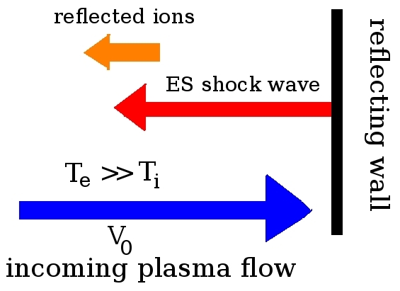
Fig. 1 shows the schematic set-up for our 1D simulations. A shock wave is produced by reflection of a high-speed
electron-ion plasma off a conducting
wall. The shock forms due to the interaction between the incoming and reflected flows and propagates away from the wall.
We measure the density of plasma components in units of the unperturbed density , coordinates in units of the
Debye length of the unperturbed plasma flow
velocity in units of the electron thermal speed and time and electric field in units of
and correspondingly.

In out PIC simulations, we ensure the high enough resolution to resolve low-density regions, sharp gradients,
and the dynamics of both electrons and ions by taking at least 100 particles per cell and a spatial resolution
better than 0.05 For reference, in all simulations shown the conducting wall is located at and
the plasma flow impinges on it at
Within these settings, the dimensionless input parameter which determines the evolution of the plasma flows is where
is the speed of unperturbed plasma flow and is the sound speed.
Moreover, the stability of the soliton and the formation of the shock are proven to be strongly dependent on the velocity distribution of
ionsMacchiPRE , thus on the fraction .
Note, that this purely electrostatic approach is reasonable for quasi-parallel shocks as it treats scales
(as very often), thus providing an important microphysics ingredient
for the diffusive shock acceleration as well DSA ; DSA1 ; DSA2 . The hybrid simulations, broadly used
in astro-geo-shocks studies, do not resolve these scales since they treat electrons as a fluid.
III Simulation results
III.1 Cold upstream ions
The evolution of the distribution of ions on phase plane for is shown in Fig. 2 a)–d). By the flows interacted and the shock is formed. The isolated density (and electrostatic potential) structures, Fig. 2 e)–f), have the characteristic width of several Ions reflected from the shock are clearly visible on the phase plane. In the case of cold upstream ions the ions are reflected at a single point where the potential reaches its maximum and the electric field has a jump and the potential profile a cusp.


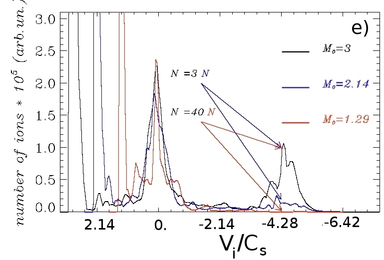
The number of ions reflected out of the shock increases with the increasing of the flow velocity, see Fig. 3, where the distributions of ions on the phase plane and the distribution functions of ions at are shown. The distribution function has three distinct peaks: inflowing ions (), reflected ions ( with the speed of the reflecting hump), and ions at rest downstream of the shock. The energy spectrum of the reflected ions is very broad.


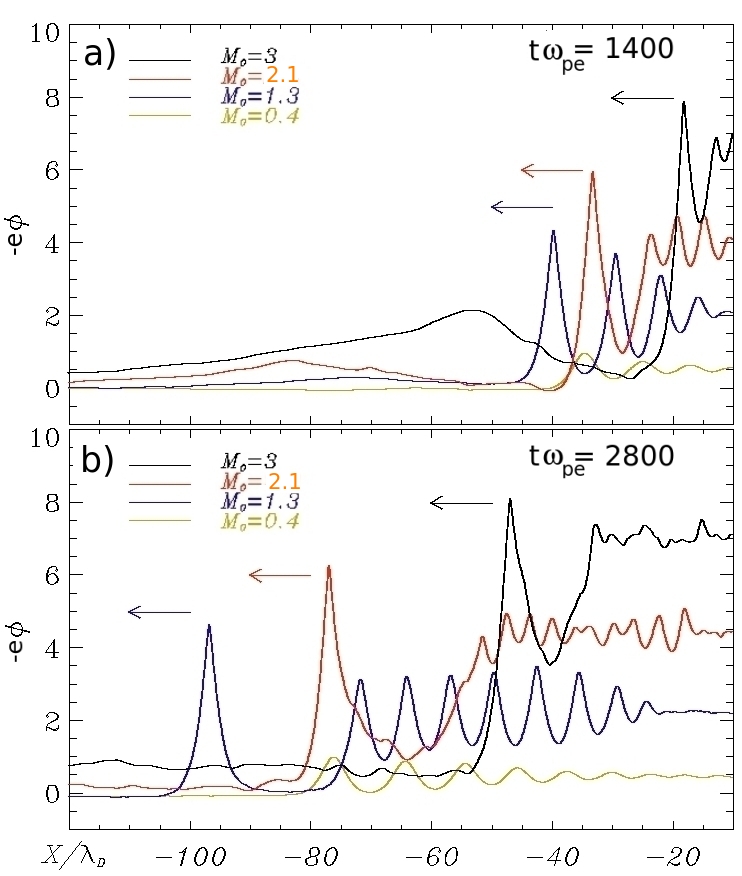
The spatial distributions of the electrostatic potential () for different values of upstream flow are presented in Fig. 4 a)–b). It is clearly seen that when the ions begin to reflect from the soliton tip, the classical single solution bifurcates into a more complex structure that comprises the leading soliton, the periodic wave train downstream of it and the foot occupied by the reflected ions. This foot is supported by the reflected ions and also accelerates them somewhat further. Because of the reflection of cold ions the leading soliton for and acquire a clear cusp structure.
The particle reflection strongly depends of the amplitude of the shock (overshoot of electrostatic potential). In turn it alters the
shock amplitude and speed, and thus the reflection threshold. Moreover, the reflected ions perturb the electrostatic potential upstream
which changes the speed of inflowing ions and thus, again, the condition for the ensuing reflection. For and
the shock looses much of its momentum because of the ion reflection, for the number of reflected ions is very small. Momentum
conservation suggests that ion reflection slows down the shock, thus decreasing its amplitude. Evidently, decreasing amplitude acts against
reflection. However, if the amplitude drops below the reflection threshold for a given speed,
the shock amplitude
should recover and the reflection will resume. By virtue of these feedback loops the reflection efficiency can be expected to either stay at a
self-organized critical level or to exhibit cyclic dynamics. Numerical simulations and observations
validate both scenarios, though, the cyclic shock behavior was primarily observed in magnetized
plasma environments cyclic ; cyclic1 . The temporal evolution of the maximum value () of the electrostatic potential
extracted from our simulations, Fig. 4 c) (solid line), confirms a cyclic behavior of the shock.


The approximate velocity of the shock with respect to the upstream flow can be defined from the position of the maximum of the electrostatic potential (dashed curves in Fig. 4 c)). The result is shown in Fig. 4 d). Measured in units of this velocity directly represents the shock Mach number Our simulations prove that the solution, consisting of the leading soliton, periodic wave train downstream and the foot occupied by the reflected ions persists with the increasing Mach numbers up to a critical value of until almost all incident ions get reflected. In case of cold ions this critical value is reached for the upstream velocity The obtained critical value of is much beyond a critical value , at which the shock is about to reflect some of the upstream ions. For the cold upstream ions and Bolzmannian electrons (this is definitely not the case in our simulations) Sagdeev , for adiabatically trapped electrons Gurevich . Note, that in the early days of collisionless shock research the existence of stationary shock transitions for Mach numbers exceeding critical has been often disfavored.

When the velocity of the incoming flow is bigger than the solution becomes qualitatively very different. An almost monoenergetic beam of ions, produced by the reflection of the inflowing ions with is clearly seen in Fig.5. Note also the sharp peak in the distribution function () and the significant deceleration of the inflowing ions () for The next qualitative change in the solution should occur when the inflow velocity reaches the values comparable to the thermal velocity of the electrons. At this point the Buneman instability starts to play an important role in the interaction of flows. This regime is however outside the current study.

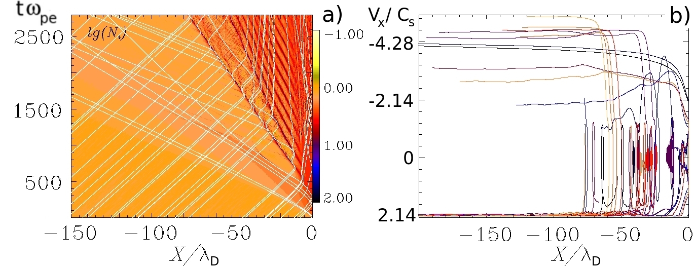
Finally, frame a) of Fig. 6 shows the distribution of ion density in logarithmic scale and the time history of some selected ions. The first peak in the ion density corresponds to the “outrunner” soliton, liberated from its dispersive trail. The velocity of this soliton is almost constant in time (apart from the oscillations, mentioned before) and it reflects a lot of incoming ions, which then escape with double the shock speed, see also Fig. 6 b). The trail, instead, not only propagates with a smaller velocity, it slows down significantly as well. Some of the ions get trapped between the soliton and the leading part of the trail.

III.2 Warm upstream ions
The resolution of our PIC simulations is high enough to accurately include the finite ion temperature in our analysis. Fig.7 shows the distributions of ions on the phase plane for (very slow upstream flow) and cold/warm upstream ions. If the upstream ions are cold () only a negligibly small number of them get reflected, but if the final distribution function of ions assumes a different shape. In Fig.7 a steady reflection of ions is clearly visible for Their number remains, however, very small and the energy spectrum – quite broad. Moreover, there are ions trapped in the “multipeaks”. Note, that stability of solitons and formation of the electrostatic shock waves in ultraintense laser interaction with overdense plasmas are also found to be strongly dependent on the velocity distribution of ionsMacchiPRE . It should be mentioned, that if the flow velocity of warm (both electrons and ions) inflowing plasma exceeds the solution qualitatively similar to Fig.5 forms again: the reflection produces a huge amount of almost monoenergetic ions which propagate away from the shock.
IV Conclusion
Our simulations show that (i) when the Mach number of the acoustic soliton increases to the point of ion reflection and the soliton transforms into a soliton train downstream, this structure persists with increasing Mach number until almost all incident ions get reflected; (ii) the ion reflection alters the shock amplitude and speed, thus impacting the reflection threshold itself; (iii) the pedestal of the electrostatic potential, supported by the reflected ions, changes the speed of inflowing ions and thus again, the condition for the ensuing reflection. The formation of the pedestal in the potential between the reflecting hump and the front edge of the group of reflected ions makes the analytic theory very challenging. In fact, this pedestal is sensitive to the model used for the transition between the reflected ions and upstream (e.g. cold vs hot beam of reflected ions). In the pedestal the inflowing plasma is slowed down considerably, if its front edge moves at the speed of the main shock, but reflected particles pass through it and accelerate, decreasing their density. All these uncertainties are critical and hard to resolve without simulations. Note, that an analytic solution for the ion-acoustic collisionless shock with self-consistently reflected ions and their subsequent cooling was recently presented IAshock13 ; IAshock14 . Its relation to the well known non-reflecting ion-acoustic soliton solution, strictly limited by the critical Mach number (Boltzmann electrons)Sagdeev and (trapped electrons) Gurevich , was clarified and quantified.
This work was in part supported by the DFG within the SFB 652 and by RSCF under the Grant 14-11-00485. PIC simulations were performed using the computing resources granted by the John von Neumann-Institut for Computing (Research Center Jülich) under the project HRO03.
References
- (1) R.Z. Sagdeev, Reviews of Plasma Physics 4, 23 (1966).
- (2) C. F. Kennel, J. P. Edmiston, and T. Hada, Washington DC AGU Geophysical Monograph Series 34, 1 (1985).
- (3) K. Papadopoulos, Washington DC AGU Geophysical Monograph Series 34, 59 (1985).
- (4) R. Blandford and D. Eichler, Phys. Rep. 154, 1 (1987).
- (5) M. A. Malkov & L. O’C. Drury, Reports on Progress in Physics 64, 429 (2001).
- (6) R. Blandford, P. Simeon, and Y. Yuan, ArXiv e-prints, 1409.2589 (2014).
- (7) S. V. Bulanov et al., Physics Letters A 299, 240, (2002).
- (8) D. Haberberger et al., Nature Physics 8, 95 (2012).
- (9) F. Fiuza et al., Phys. Plasmas 20, 056304 (2013).
- (10) O. Adriani et al., Science 332, 69 (2011).
- (11) A.V. Gurevich, Soviet J. of Exp.and Theoretical Phys. 26, 575 (1968).
- (12) S. S. Moiseev & R. Z. Sagdeev, J. of Nuclear Energy 5, 43 (1963).
- (13) G. A. Mourou, T. Tajima, & S. V. Bulanov, Rev. Mod. Phys. 78, 309 (2006).
- (14) C. A. J. Palmer et al., Phys. Rev. Lett. 106, 014801 (2011).
- (15) A. Macchi, M. Borghesi, & M. Passoni, Rev. Mod. Phys. 85, 751 (2013).
- (16) L. Romagnani et al., Phys.Rev.Lett. 101, 025004 (2008).
- (17) G. Sorasio et al., Phys. Rev. Lett. 96, 045005 (2006).
- (18) J.M. Dawson, Rev. Mod. Phys. 55, 403 (1983).
- (19) A. Macchi, A. S. Nindrayog, & F. Pegoraro, Phys.Rev. E. 85, 046402 (2012).
- (20) L. O’C. Drury, Reports on Progress in Physics 46, 973 (1983).
- (21) L. O’C. Drury, Astroparticle Physics, 39, 52 (2012).
- (22) A. R. Bell, Brazilian Journal of Physics, 44, 415 (2014).
- (23) D. Burgess, E. Möbius and M. Scholer, Space Sci. Rev. 173 (2012).
- (24) D. Caprioli, A.-R. Pop, & A. Spitkovsky, Astrophys. J. Lett. 798, L28 (2015).
- (25) R.Z. Sagdeev et al. DPP13 Meeting of The American Physical Society, Denver, USA. Abstract ID: BAPS.2013.DPP.GP8.106 (2013).
- (26) M.A. Malkov et al., DPP14 Meeting of The American Physical Society, New Orleans, USA. Abstract ID: BAPS.2014.DPP.CP8.75 (2014).