Normal-dispersion Microcombs Enabled by Controllable Mode Interactions
Abstract
We demonstrate a scheme incorporating dual coupled microresonators through which mode interactions are intentionally introduced and controlled for Kerr frequency comb (microcomb) generation in the normal dispersion region. Microcomb generation, repetition rate selection, and mode locking are achieved with coupled silicon nitride microrings controlled via an on-chip microheater. Our results show for the first time that mode interactions can be programmably tuned to facilitate broadband normal-dispersion microcombs. The proposed scheme increases freedom in microresonator design and may make it possible to generate microcombs in an extended wavelength range (e.g., in the visible) where normal material dispersion is likely to dominate.
Microresonator-based Kerr frequency comb (microcomb) generation is a promising technique with many advantages including very compact size, high repetition rate, and (sometimes) wide bandwidth Kippenberg et al. (2011). Many applications can potentially benefit from this revolutionary technique, such as optical communications Pfeifle et al. (2014), photonic radio-frequency signal processing Xue et al. (2014), and optical clocks Papp et al. (2014). The initial stage of comb formation inside the microresonator is triggered by modulational instability which is enabled by Kerr nonlinearity and group velocity dispersion. Anomalous dispersion has been widely exploited Del’Haye et al. (2007); Levy et al. (2010); Razzari et al. (2010); Savchenkov et al. (2011); Foster et al. (2011); Okawachi et al. (2011); Papp and Diddams (2011); Grudinin et al. (2012); Herr et al. (2012); Wang et al. (2013a); Saha et al. (2013); Herr et al. (2014); Del’Haye et al. (2014), while normal dispersion has often been thought unsuitable for microcomb generation due to the lack of modulational instability on the upper branch of the bistable pump field in the normal dispersion region Haelterman et al. (1992); Coen and Haelterman (1997); Hansson et al. (2013). Nevertheless, comb generation in normal-dispersion microresonators has by now been reported several times Ferdous et al. (2011); Wang et al. (2012); Savchenkov et al. (2012); Coillet et al. (2013); Wang et al. (2013b); Liang et al. (2014); Xue et al. ; Liu et al. (2014); Huang et al. (2015). Normal-dispersion microcombs are of particular interest as normal dispersion is easy to access in most nonlinear materials. It has been found that modulational instability may occur in the normal dispersion region with the aid of coupling between different family modes Savchenkov et al. (2012); Xue et al. ; Liu et al. (2014); Ramelow et al. (2014). However, the mode interactions employed so far in a single microresonator are related to accidental degeneracies associated with different spatial modes and are hence very difficult to control and modify. In this letter, we demonstrate a novel scheme which for the first time permits programmable and reliable control of mode interactions to achieve repetition-rate-selectable and mode-locked combs from normal dispersion microresonators.
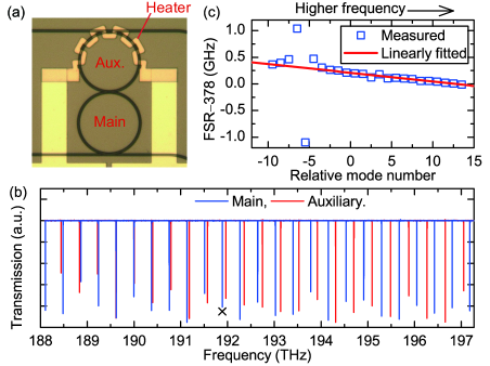
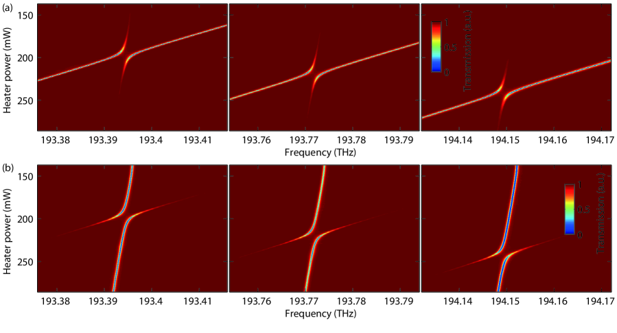
Figure 1(a) shows the microscope image of our device which is based on the well-known coupled-microresonator structure Popović et al. (2006); Gentry et al. (2014). Two silicon nitride (SiN) microrings (main and auxiliary) are coupled to each other. Each ring is also coupled to its own bus waveguide, which allows either transmission measurements or pump injection. Figure 1(b) shows the linear transmission curves of the two rings measured at room temperature by scanning the frequency of a low-power laser. The cross-section of the waveguide from which the microrings are formed is . Unlike most on-chip microresonators that have been used for comb generation, this waveguide dimension supports only single transverse mode. The radii of the two rings are different (main: ; auxiliary: ), corresponding to different free spectral ranges (FSRs) (main: 378 GHz; auxiliary: 391 GHz). Figure 1(c) shows the FSR of the main ring versus the relative mode number measured by using frequency comb assisted spectroscopy Del’Haye et al. (2009). The dispersion is determined from the slope of the curve and is given by , where the parameter signifies the change in FSR from one pair of resonances to the next Herr et al. (2012, 2014). This corresponds to and is clearly in the normal dispersion regime.
It can be observed in Fig. 1(c) that the approximately linear variation of the FSR curve is disturbed around mode . This is a signature of coupling between the modes of the two rings when their resonant frequencies are close to each other Liu et al. (2014); Ramelow et al. (2014); Del’Haye et al. (2009) (see the mode crossing area around 189.5 THz in Fig. 1(b)). The resonances of the auxiliary ring can be thermally shifted via a microheater. Figures 2(a) and 2(b) show the zoomed-in transmission spectra versus the heater power for the auxiliary ring and the main ring, measured at their respective bus waveguides. The thermal shifting efficiency of the auxiliary ring is . The resonances of the main ring are also shifted slightly () as no special efforts were made to optimize the thermal isolation. The resonances in the mode crossing region are split due to the coupling between the rings, a behavior similar to that in quantum mechanical perturbation theory Landau and Lifshitz (2003). The two new resonances evident in the transmission spectra push each other leading to avoided crossings. The effect of mode interaction decreases for heater powers at which the (unperturbed) resonant frequencies of the main ring and auxiliary ring are further separated. Away from the mode-crossing region, one of the resonant features disappears from the transmission spectrum; the remaining resonance recovers to the case with nearly no mode coupling. Naturally, which resonant feature remains outside of the mode-crossing region depends on whether the spectrum is measured from the upper or lower bus waveguide. By changing the heater power, we are able to selectively split and shift an individual resonance.
Denote the field amplitude in the main and auxiliary rings and with time dependences and , respectively. The fields obey the following coupled-mode equations Haus and Huang (1991); Novotny (2010)
| (1) | |||||
| (2) |
where , are the decay rates of the main and auxiliary ring, respectively; is the coupling rate. and are related to the loaded cavity quality factors (’s) by , .
The eigenvalues of Eqs. (1) and (2) are where
| (3) | |||||
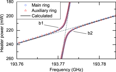
The real parts of are the new resonant frequencies affected by mode coupling, and the imaginary parts are the decay rates. Figure 3 shows the resonant frequencies of the main and auxiliary rings in the mode-splitting region around 193.77 THz. Also shown are the calculated results with , , and . Here the ’s are extracted from the linewidths of the transmission resonances measured away from the mode-crossing region, while is adjusted to fit the data of Fig. 3. The agreement between calculation and measurement is excellent. Note that the curves acquired by measuring the transmission at either the top or bottom waveguide agree essentially perfectly, which is expected since in either case we are probing the same hybridized resonances. One of the hybridized resonances is red shifted (branch “b1”) with respect to the original resonances assuming no mode splitting, while the other is blue shifted (branch “b2”). In comb generation, the resonance shifts play a key role in creating phase matched conditions enabling modulational instability.
For comb generation, the pump laser is slowly tuned into resonant mode 0 of the main ring from the blue side. In this process, the intracavity pump field stays on the upper branch of the bistability curve where modulational instability is absent in a normal-dispersion microresonator undisturbed by mode interactions Haelterman et al. (1992); Coen and Haelterman (1997); Hansson et al. (2013). With our coupled-microring scheme, interactions are intentionally introduced and controlled by thermally tuning the auxiliary ring to facilitate comb generation. At the initial stage of comb formation, essentially only three resonant modes are involved: the pumped mode and the two sideband modes where new frequency components first start to grow. The effect of dispersion corresponds to unequal distances between these three modes (). Define the resonance asymmetry factor by which is a generalization of the parameter to a form relevant to modulational instability at the resonant modes. Note that positive corresponds to an anomalous dispersion, for which modulational instability may occur, while negative corresponds to normal dispersion. By selectively splitting one of the sideband modes or , the asymmetry factor may be changed so that an equivalent anomalous dispersion is achieved ( becomes positive) involving the blue shifted sideband mode (branch “b2” in Fig. 3). Modulational instability thus becomes possible, leading to generation of initial comb lines. More comb lines can be generated through cascaded four-wave mixing resulting in a broadband frequency comb.
Note that the equivalent dispersion achieved with our scheme is different from the general microresonator dispersion which is represented to the first order by an FSR change linear in mode number. As pointed out above, splitting and shifting of just one resonance is enough for the modulational instability to occur; this is distinct from the usual smooth change of FSR over a series of resonant modes. As a result our scheme is easy to implement and offers an alternative to wideband dispersion engineering Savchenkov et al. (2011); Riemensberger et al. (2012). The equivalent dispersion is related to the resonance asymmetry factor by where is the refractive index, the speed of light in vacuum, and is the FSR (Hz) at . For the dual coupled SiN microrings we employed, the resonance shifts due to mode splitting can be several GHz. When , this corresponds to an equivalent dispersion change on the order of , which is very difficult to achieve by tailoring the microresonator geometry Savchenkov et al. (2011); Riemensberger et al. (2012). The large equivalent dispersion makes it possible to directly generate 1-FSR combs as the peak frequency of modulational instability gain is inverse to the dispersion Haelterman et al. (1992); Hansson et al. (2013). This may prove especially useful for large microresonators with small FSRs Liu et al. (2014), where without mode interactions achieving direct 1-FSR comb generation is difficult. Direct generation of 1-FSR combs offers the advantage of easy to access phase locked states Herr et al. (2012); Ferdous et al. (2011); Wang et al. (2012, 2013b).
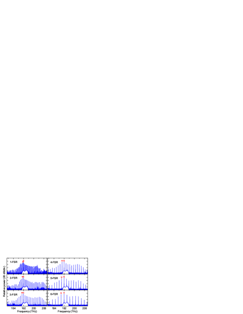
By controlling the mode interaction location, the initial comb lines can be selectively generated at specified resonances, giving rise to a repetition-rate-selectable comb. Figure 4 shows the results when the off-chip pump power is 1 W (0.5 W on chip). The comb repetition rate is tuned from 1-FSR () to 6-FSR () while maintaining a similar comb spectral envelope. All the combs exhibit low intensity noise (below our experimental sensitivity) directly upon generation. High coherence is thus anticipated Ferdous et al. (2011); Wang et al. (2012).
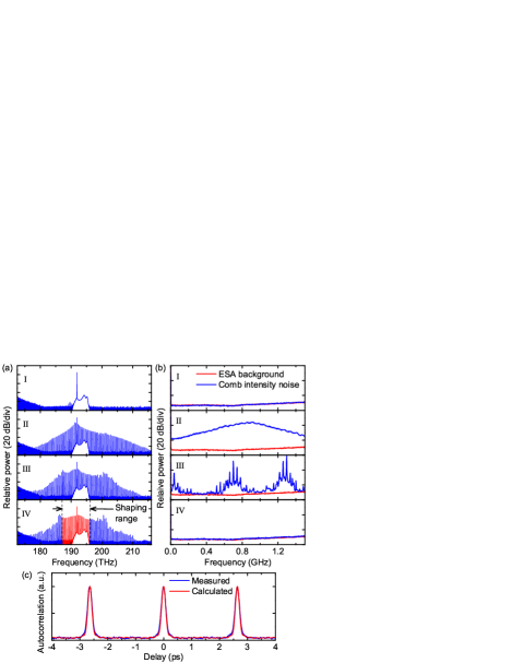
Mode-locking transitions, in which the comb first shows high intensity noise and then transitions to a low-noise state, are also observed. Figure 5 shows the results with 1.8 W off-chip pump power. The strongest mode interaction is experienced by the first mode to the red side of the pump. By changing the heater power, the spectrum first shows no comb (Fig. 5(a) I and Fig. 5(b) I), then a 1-FSR comb which at this pump power is generated with high intensity noise (Fig. 5(a) II, III and Fig. 5(b) II, III). By further optimizing the heater power, the comb intensity noise suddenly drops below the equipment level (Fig. 5(a) IV and Fig. 5(b) IV). The low-noise comb is relatively broad with a 10-dB bandwidth of around 15 THz (120 nm). To further verify the mode-locked state of the comb, a fraction of the comb spectrum is selected and phase compensated line-by-line by using a pulse shaper in the lightwave C+L band. The autocorrelation trace of the compressed pulse, shown in Fig. 5(c), is in good agreement with the calculated result assuming ideal phase compensation (autocorrelation width 200 fs, corresponding to 130-fs pulse width). The ability to fully compress to a transform-limited pulse suggests high coherence of the low-noise comb Ferdous et al. (2011).
In summary, we have demonstrated a novel scheme incorporating coupled microresonators for Kerr frequency comb generation in the normal dispersion region. The dynamics of comb formation can be controlled by adjusting the interactions between the microresonators. Repetition rate selection and broadband mode-locking transitions are achieved with coupled SiN microrings. By incorporating a microheater to tune the dual rings into resonance and avoiding accidental degeneracies associated with few-moded waveguides, our scheme shows for the first time a reliable design strategy for normal-dispersion microcombs. As normal dispersion is easy to access in most nonlinear materials, the proposed scheme facilitates microcomb generation and is of particular importance in wavelength ranges (e.g., the visible) where the material dispersion is likely to dominate.
Acknowledgements.
This work was supported in part by by the Air Force Office of Scientific Research under grant FA9550-12-1-0236 and by the DARPA PULSE program through grant W31P40-13-1-0018 from AMRDEC.References
- Kippenberg et al. (2011) T. J. Kippenberg, R. Holzwarth, and S. A. Diddams, Science 332, 555 (2011).
- Pfeifle et al. (2014) J. Pfeifle et al., Nature Photon. 8, 375 C (2014).
- Xue et al. (2014) X. Xue et al., J. Lightwave Technol. 32, 3557 (2014).
- Papp et al. (2014) S. B. Papp et al., Optica 1, 10 (2014).
- Del’Haye et al. (2007) P. Del’Haye et al., Nature 450, 1214 (2007).
- Levy et al. (2010) J. S. Levy et al., Nature 4, 37 (2010).
- Razzari et al. (2010) L. Razzari et al., Nature 4, 41 (2010).
- Savchenkov et al. (2011) A. A. Savchenkov et al., Nature Photon. 5, 293 (2011).
- Foster et al. (2011) M. A. Foster et al., Opt. Express 19, 14233 (2011).
- Okawachi et al. (2011) Y. Okawachi et al., Opt. Lett. 36, 3398 (2011).
- Papp and Diddams (2011) S. B. Papp and S. A. Diddams, Phys. Rev. A 84, 053833 (2011).
- Grudinin et al. (2012) I. Grudinin, L. Baumgartel, and N. Yu, Opt. Express 20, 6604 (2012).
- Herr et al. (2012) T. Herr et al., Nature Photon. 6, 480 (2012).
- Wang et al. (2013a) C. Wang et al., Nature Comm. 4, 1345 (2013a).
- Saha et al. (2013) S. Saha et al., Opt. Express 21, 1335 (2013).
- Herr et al. (2014) T. Herr et al., Nature Photon. 8, 145 (2014).
- Del’Haye et al. (2014) P. Del’Haye, K. Beha, S. B. Papp, and S. A. Diddams, Phys. Rev. Lett. 112, 043905 (2014).
- Haelterman et al. (1992) M. Haelterman, S. Trillo, and S. Wabnitz, Opt. Commun. 91, 401 (1992).
- Coen and Haelterman (1997) S. Coen and M. Haelterman, Phys. Rev. Lett. 79, 4139 (1997).
- Hansson et al. (2013) T. Hansson, D. Modotto, and S. Wabnitz, Phys. Rev. A 88, 023819 (2013).
- Ferdous et al. (2011) F. Ferdous et al., Nature Photon. 5, 770 (2011).
- Wang et al. (2012) P.-H. Wang et al., Opt. Express 20, 29284 (2012).
- Savchenkov et al. (2012) A. A. Savchenkov et al., Opt. Express 20, 27290 (2012).
- Coillet et al. (2013) A. Coillet et al., IEEE Photonics J. 5, 6100409 (2013).
- Wang et al. (2013b) P.-H. Wang et al., Opt. Express 21, 22441 (2013b).
- Liang et al. (2014) W. Liang et al., Opt. Lett. 39, 2920 (2014).
- (27) X. Xue et al., arXiv:1404.2865v4 .
- Liu et al. (2014) Y. Liu et al., Optica 1, 137 (2014).
- Huang et al. (2015) S.-W. Huang et al., Phys. Rev. Lett. 114, 053901 (2015).
- Ramelow et al. (2014) S. Ramelow et al., Opt. Lett. 39, 5134 (2014).
- Popović et al. (2006) M. A. Popović, C. Manolatou, and M. R. Watts, Opt. Express 14, 1208 (2006).
- Gentry et al. (2014) C. M. Gentry, X. Zeng, and M. A. Popović, Opt. Lett. 39, 5689 (2014).
- Del’Haye et al. (2009) P. Del’Haye et al., Nature 3, 529 (2009).
- Landau and Lifshitz (2003) L. D. Landau and E. M. Lifshitz, Quantum mechanics: nonrelativistic theory (3rd ed) (Butterworth-Heinemann, 2003).
- Haus and Huang (1991) H. A. Haus and W. Huang, Proceedings of the IEEE 79, 1505 (1991).
- Novotny (2010) L. Novotny, Am. J. Phys. 78, 1199 (2010).
- Riemensberger et al. (2012) J. Riemensberger et al., Opt. Express 20, 27661 (2012).