Ultra-low phase noise all-optical microwave generation setup based on commercial devices
Abstract
In this paper, we present a very simple design based on commercial devices for the all-optical generation of ultra-low phase noise microwave signals. A commercial, fibered femtosecond laser is locked to a laser that is stabilized to a commercial ULE Fabry-Perot cavity. The 10 GHz microwave signal extracted from the femtosecond laser output exhibits a single sideband phase noise at 1 Hz Fourier frequency, at the level of the best value obtained with such “microwave photonics” laboratory experiments Fortier2011 . Close-to-the-carrier ultra-low phase noise microwave signals will now be available in laboratories outside the frequency metrology field, opening up new possibilities in various domains.
I Introduction
Ultra-low phase noise microwave signals are being used in a growing number of fields. Industrial applications include telecommunication networks, deep-space navigation, high-speed sampling Valley2007 and radar systems Scheer1990 . Fundamental physics tests and research experiments also benefit from ultra-stable microwave signals, as in atomic fountain clocks setups Guena2012 , Lorentz invariance tests Stanwix2005 or Very Long Baseline Interferometry Grop2010 .
Such signals are usually generated in three different ways: from a quartz resonator, included in a frequency synthesis Francois2014 ; Lautier2014 ; from a sapphire oscillator Green2006 , often cooled down to cryogenic temperatures Grop2010a ; Hartnett2012 ; or from the optical domain, using an optoelectronic oscillator Salik2007 or a cavity-stabilized laser and an optical frequency comb Millo2009b ; Fortier2011 . In the latter case, a laser is locked to an ultra-stable Fabry-Perot (FP) cavity, thus providing an ultra-low phase noise optical signal and a short-term relative frequency stability below . This signal is used to phase-lock the repetition rate of an optical frequency comb, which allows for dividing down the signal frequency from the optical to the microwave domain with minimal degradation Zhang2011 . Progress in the past ten years has allowed to reach extremely low levels of relative frequency stability for FP cavity laser stabilization setups, both by improving the design Webster2008 ; Millo2009a ; Swallows2012 and materials Seel1997 ; Kessler2012 of the cavities. On the other hand, compact and portable FP cavities have been developped for field operation Leibrandt2011 ; Webster2011 , and such setups are now commercially available. Fiber-based optical frequency combs have followed the same path and are becoming an essential tool in various experimental physics laboratories.
In this article, we present a setup for all-optical microwave generation based on both a commercial Fabry-Perot cavity and a commercial fibered optical frequency comb. We use this setup to generate an ultra-stable reference signal at 10 GHz, which will later be distributed through the laboratory for future phase-noise characterizations of other oscillators based on Sapphire, Quartz or optical resonators. It will also be complementary to an optical reference signal distributed to French time and frequency laboratories through the REFIMEVE+ network Refimeve . In the following sections, we outline the 10 GHz signal generation scheme and analyse the measured signal phase noise and frequency stability.
II All-optical microwave generation setup
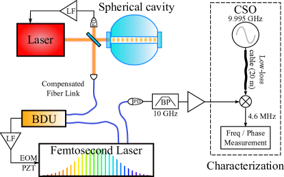
Our setup for all-optical microwave signal generation is described in Figure 1. A commercial continuous-wave (CW) laser at 1542 nm NKT is locked to a Fabry-Perot cavity using the Pound-Drever-Hall (PDH) technique. The ultra-stable cavity is a 5 cm long commercial spherical cavity ATF based on a design by NIST Leibrandt2011 . The spherical spacer is held at an optimized angle for minimizing vibration sensitivity Leibrandt2011 . Fused-Silica mirror substrates are optically contacted to a spherical ULE spacer; ULE rings are placed on the SiO2 substrates to adjust the cavity inversion temperature Kessler2012a . The inversion temperature of our cavity was determined to be 10.5∘C, and we measured a finesse of about 400 000 for the fundamental TEM00 mode.
We estimate that the thermal noise floor of our cavity will limit the stabilized laser phase noise to at 1 Hz with a slope, corresponding to a relative frequency flicker .
The cavity is pumped to ultra-high vacuum using a 2.5 l/s ion pump. The vacuum chamber and the free-space PDH optical setup are placed on a commercial active vibration isolation platform and inside a thermal insulation box, with a total volume of about 0.25 m3. We use homemade electronics for the loop filter, as those are on hand in our laboratory and are usually lower-priced, but similar systems are commercially available. An electro-optical modulator (EOM) modulates the laser phase at to provide the PDH error signal. The fast corrections are applied to an acousto-optical modulator (AOM) with a bandwidth higher than , while the slow corrections are applied to the laser’s piezoelectric transducer(PZT), with a bandwidth of . This setup has proven to be very robust, and the laser can stay locked to the FP cavity for weeks without any external intervention.
We optically mix the stabilized laser output with an optical frequency comb produced by a commercial femtosecond laser Menlo using the so-called “beat detection unit” provided by the manufacturer. This allows for locking the femtosecond laser repetition rate at 250 MHz. A fibered interferometer is readily aligned to detect the beatnote between the optical comb and the reference laser on a high sensitivity photodetector. The output voltage is then processed to generate a lock signal and fed back to an EOM and a PZT placed inside the femtosecond laser cavity to stabilize its repetition rate. The comb carrier envelope offset is stabilized to a radio frequency reference using the so-called technique Telle1999 . This is all done using the electronics provided by the manufacturer. Our only addition is a small RF circuit that allows fo the substraction of the CEO to the optical beatnote signal, following Ref. Zhang2011 . We obtained similar results with and without this substraction scheme.
We detect the 40th harmonic of the repetition rate, near 10 GHz, using a fast photodiodeDiscovery . With an optical power of 3 mW, we obtain about microwave power at 10 GHz. This signal is band-pass filtered at 10 GHz and amplified using two low phase noise microwave amplifiers Amplis . The residual phase noise added by such optical division schemes has been measured to be about at with an earlier version of the optical frequency comb Millo2009 . In principle, this value can even be lowered to at 1 Hz using additional noise-reduction techniques Zhang2011 .
The optical fiber link between the ultra-stable laser and the optical frequency comb is actively stabilized using a fiber-noise compensation scheme Lopez2012 . A fibered AOM is used to correct for optical path fluctuations, with a bandwidth of a few tens of kHz. This can be avoided by placing the FP cavity right next to the femtosecond laser, and using a short optical fiber.
The whole microwave generation setup has stayed locked for days without intervention, even through fairly high temperature fluctuations due to a temporary failure of our air conditionning system. The PDH and the Doppler-cancellation locks have proven to be the most robust, and the femtosecond laser seems to need a quieter acoustic environment. All-in-all, the system is robust enough to continuously provide a 10 GHz ultra-stable reference signal.
III Measurements
The characterization setup of the optically generated microwave signal is illustrated in Figure 1. The output of a fast photodiode is filtered at 10 GHz, amplified, and then mixed with a 9.995 GHz signal generated by one of the Cryogenic Sapphire Oscillators (CSO) of the laboratory. The resulting 4.6 MHz beatnote is then sent to a frequency counter referenced to a Hydrogen Maser Counters . The CSO has been fully characterized and presents a relative frequency stability below for integration times between 1 and 1000 s Grop2014 . The sapphire whispering gallery mode resonator is held at cryogenic temperature near its inversion point at 6 K, and is integrated in a Pound-Galani oscillator loop. The ultra-stable output is transfered to the “microwave photonics” room through a 20 m low-loss coaxial cable without any noise compensation.
We measure a relative phase noise for the beatnote, competitive with state-of-the-art optically generated ultrastable microwave signals Fortier2011 ; Grop2014 . Figure 2 presents the phase noise spectrum. The noise floor is close to the photodetection shot noise limit at (dashed line). The spurious peaks between 1 Hz and 100 Hz belong to the CSO phase noise. In particular, resonances at 1.4 Hz and its harmonics are related to the vibrations of the cryo-cooler Grop2010a . We plot the phase noise spectrum of the beatnote between two nearly identical CSOs for reference (dashed red line). It is worth noting that the two measurements do not differ by more than 3 dB between 0.1 Hz and 100 Hz, meaning that the optically generated microwave signal phase noise is very close to the CSO signal phase noise in this frequency range. Moreover, the 20 m coaxial cable might degrade the transfered CSO signal phase noise.
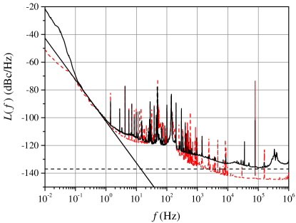
Between 0.2 Hz and 0.7 Hz, the spectrum fits the law (frequency flicker) with a value of at 1 Hz (black line). This would translate to a relative frequency stability floor of for the beatnote. The spectrum shows excess phase noise at frequencies below 0.2 Hz. We believe that this is due to temperature fluctuations in the room, which cause polarization rotations within the PDH optical setup. These rotations induce power fluctuations of the CW laser that couple to the FP cavity resonance frequency.
The phase noise of the CSO we use has been measured to be . By substracting this value to the beatnote phase noise, we obtain for the optically generated 10 GHz signal. This is very close to the expected thermal noise floor of the ultra-stable cavity .
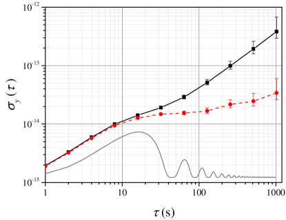
Figure 3 presents the relative frequency stability of the optically generated microwave signal versus the CSO. We obtain for the beatnote, higher than the flicker frequency floor (). This is mostly due to excess frequency noise at low frequencies. In particular, a parasitic modulation of the beatnote at (most likely due to room-temperature fluctuations) degrades the signal relative frequency stability between 1 and 20 seconds. We have numerically extracted the relative frequency power spectral density at this frequency from the drift-removed temporal dataset. We plot the relative frequency stability obtained with such a purely sinusoidal modulation added to the Flicker floor at for reference (gray line - see Kersale2006 for details). The initial slope and frequency stability fairly agrees with our measurement.
The linear drift of the frequency leads to a stability for integration time longer than 200 s. Potential improvements of the short-term relative frequency stability include the better rejection of the room-temperature fluctuations, as well as a refined measurement of the inversion temperature of the cavity.
IV Conclusion
In summary, we have presented the first all-optical setup for microwave signal generation based on commercially available instruments. This setup shows a phase noise spectrum competitive with the best reported values both for all-optical setups Fortier2011 and cryogenic sapphire oscillators Grop2010a .
To this day, such “microwave photonics” setups are still found mostly in metrology institutes, as they used to require the design of an ultra-stable FP cavity and/or optical frequency comb. The setup that we present in this article should allow the spreading of optical microwave generation outside of frequency metrology labs, thanks to the availability of the key-devices and the overall simplicity of the setup. This will pave the way to tantalizing new developments in fields such as high-resolution spectroscopy, atomic physics and very-long baseline interferometry.
V Acknowledgements
The authors would like to thank Rodolphe Boudot and Vincent Giordano for their careful reading of the manuscript as well as Christophe Fluhr for fruitful discussions about the CSO and Maser performances.
This work is funded by the Fond Européen de développement Régional (FEDER). This work is also funded by the ANR Programme d’Investissement d’Avenir (PIA) under the Oscillator IMP project and First-TF network, and by grants from the Région Franche Comté intended to support the PIA.
References
- (1) T. M. Fortier, M. S. Kirchner, F. Quinlan, J. Taylor, J. C. Bergquist, T. Rosenband, N. Lemke, A. Ludlow, Y. Jiang, C. W. Oates, and S. A. Diddams, “Generation of ultrastable microwaves via optical frequency division,” Nature Phot. 5, 425–429 (2011).
- (2) G. C. Valley, “Photonic analog-to-digital converters,” Opt. Express 15, 1955–1982 (2007).
- (3) J. A. Scheer, “Coherent radar system performance estimation,” in Record of the IEEE 1990 International Radar Conference (IEEE, 1990), pp. 125–128 (1990).
- (4) J. Guéna, M. Abgrall, D. Rovera, P. Laurent, B. Chupin, M. Lours, G. Santarelli, P. Rosenbusch, M. Tobar, R. Li, K. Gibble, A. Clairon, and S. Bize, “Progress in atomic fountains at LNE-SYRTE,” IEEE Trans. Ultrasonics Ferroelec. Freq. Control 59, 391–409 (2012).
- (5) P. L. Stanwix, M. E. Tobar, P. Wolf, M. Susli, C. R. Locke, E. N. Ivanov, J. Winterflood, and F. van Kann, “Test of lorentz invariance in electrodynamics using rotating cryogenic sapphire microwave oscillators,” Phys. Rev. Lett. 95, 040404 (2005).
- (6) S. Grop, P.-Y. Bourgeois, N. Bazin, Y. Kersalé, E. Rubiola, C. Langham, M. Oxborrow, D. Clapton, S. Walker, J. De Vicente, and V. Giordano, “ELISA: A cryocooled 10 GHz oscillator with frequency stability,” Rev. Sci. Instrum. 81, 025102–025102–7 (2010).
- (7) B. François, C. E. Calosso, J. M. Danet, and R. Boudot, “A low phase noise microwave frequency synthesis for a high-performance Cesium vapor cell atomic clock,” Rev. Sci. Instrum. 85, 094709 (2014).
- (8) J. Lautier, M. Lours, and A. Landragin, “A compact micro-wave synthesizer for transportable cold-atom interferometers,” arXiv:1406.2911 [physics.atom-ph] (2014).
- (9) D. Green, C. McNeilage, and J. Searls, “A low phase noise microwave sapphire loop oscillator,” in Proceedings of IEEE International Frequency Control Symposium and Exposition (IEEE, 2006), pp. 852–860.
- (10) S. Grop, P.-Y. Bourgeois, R. Boudot, Y. Kersalé, E. Rubiola, and V. Giordano, “10 GHz cryocooled sapphire oscillator with extremely low phase noise,” Electronics Lett. 46, 420–422 (2010).
- (11) J. G. Hartnett, N. R. Nand, and C. Lu, “Ultra-low-phase-noise cryocooled microwave dielectric-sapphire-resonator oscillators,” App. Phys. Lett. 100, 183501 (2012).
- (12) E. Salik, N. Yu, and L. Maleki, “An ultralow phase noise coupled optoelectronic oscillator,” IEEE Photonics Technology Lett. 19, 444–446 (2007).
- (13) J. Millo, M. Abgrall, M. Lours, E. M. L. English, H. Jiang, J. Guéna, A. Clairon, M. E. Tobar, S. Bize, Y. Le Coq, and G. Santarelli, “Ultralow noise microwave generation with fiber-based optical frequency comb and application to atomic fountain clock,” App. Phys. Lett. 94, 141105 (2009).
- (14) W. Zhang, Z. Xu, M. Lours, R. Boudot, Y. Kersalé, A. Luiten, Y. Le Coq, and G. Santarelli, “Advanced noise reduction techniques for ultra-low phase noise optical-to-microwave division with femtosecond fiber combs,” IEEE Trans. Ultrasonics, Ferroelec. Freq. Control 58, 900–908 (2011).
- (15) S. A. Webster, M. Oxborrow, S. Pugla, J. Millo, and P. Gill, “Thermal-noise-limited optical cavity,” Phys. Rev. A 77, 033847 (2008).
- (16) J. Millo, D. V. Magalhães, C. Mandache, Y. Le Coq, E. M. L. English, P. G. Westergaard, J. Lodewyck, S. Bize, P. Lemonde, and G. Santarelli, “Ultrastable lasers based on vibration insensitive cavities,” Phys. Rev. A 79, 053829 (2009).
- (17) M. D. Swallows, M. J. Martin, M. Bishof, C. Benko, Y. Lin, S. Blatt, A. M. Rey, and J. Ye, “Operating a 87Sr optical lattice clock with high precision and at high density,” IEEE Trans. Ultrasonics Ferroelec. Freq. Control 59, 416–425 (2012).
- (18) S. Seel, R. Storz, G. Ruoso, J. Mlynek, and S. Schiller, “Cryogenic optical resonators: A new tool for laser frequency stabilization at the 1 Hz level,” Phys. Rev. Lett. 78, 4741–4744 (1997).
- (19) T. Kessler, C. Hagemann, C. Grebing, T. Legero, U. Sterr, F. Riehle, M. J. Martin, L. Chen, and J. Ye, “A sub-40-mHz-linewidth laser based on a silicon single-crystal optical cavity,” Nature Phot. 6, 687–692 (2012).
- (20) D. R. Leibrandt, M. J. Thorpe, M. Notcutt, R. E. Drullinger, T. Rosenband, and J. C. Bergquist, “Spherical reference cavities for frequency stabilization of lasers in non-laboratory environments,” Opt. Express 19, 3471–3482 (2011).
- (21) S. Webster and P. Gill, “Force-insensitive optical cavity,” Opt. Lett. 36, 3572–3574 (2011).
- (22) http://www.refimeve.fr/index.php/en/.
- (23) NKT Photonics Koheras Adjustik fiber laser.
- (24) The cavity is provided by Advanced Thin Films, and the vacuum housing by Stable Laser Systems.
- (25) T. Kessler, T. Legero, and U. Sterr, “Thermal noise in optical cavities revisited,” J. Opt. Soc. Am. B 29, 178–184 (2012).
- (26) Menlo systems FC1500-250-WG, Er fiber-based modelocked laser.
- (27) H. R. Telle, G. Steinmeyer, A. E. Dunlop, J. Stenger, D. H. Sutter, and U. Keller, “Carrier-envelope offset phase control: A novel concept for absolute optical frequency measurement and ultrashort pulse generation,” App. Phys. B 69, 327–332 (1999).
- (28) From Discovery Semiconductors, inc.
- (29) Hittite HMC606LC5 and Miteq AFS6-08001600-15-10P-6.
- (30) J. Millo, R. Boudot, M. Lours, P.-Y. Bourgeois, A. N. Luiten, Y. Le Coq, Y. Kersalé, and G. Santarelli, “Ultra-low-noise microwave extraction from fiber-based optical frequency comb,” Opt. Lett. 34, 3707–3709 (2009).
- (31) O. Lopez, A. Haboucha, B. Chanteau, C. Chardonnet, A. Amy-Klein, and G. Santarelli, “Ultra-stable long distance optical frequency distribution using the internet fiber network,” Opt. Express 20, 23518–23526 (2012).
- (32) We have used a KnK counter to obtain the stability curve presented in this manuscript, and a Symmetricom 5125A to acquire the phase noise traces. Both counters give the same result for stability measurements.
- (33) S. Grop, C. Fluhr, J.-L. Masson, Y. Kersalé, E. Rubiola, V. Giordano, B. Dubois, and G. Haye, “Latest improvements in the performance of a cryogenic sapphire oscillator,” in “European Time and Frequency Forum,” (2014).
- (34) Y. Kersalé, N. Boubekeur, M. Chaubet, N. Bazin, and V. Giordano, “New temperature compensated sapphire-rutile resonator oscillator,” in Proceedings of IEEE International Frequency Control Symposium and Exposition (IEEE, 2006), pp. 695–698.