A novel fast timing micropattern gaseous detector: FTM
Abstract
In recent years important progress in micropattern gaseous detectors has been achieved in the use of resistive material to build compact spark-protected devices. The novel idea presented here consists of the polarisation of WELL structures using only resistive coating. This allows a new device to be built with an architecture based on a stack of several coupled layers where drift and WELL multiplication stages alternate in the structure. The signals from each multiplication stage can be read out from any external readout boards through the capacitive couplings. Each layer provides a signal with a gain of . The main advantage of this new device is the dramatic improvement of the timing provided by the competition of the ionisation processes in the different drift regions, which can be exploited for fast timing at the high luminosity accelerators (e.g. HL-LHC upgrade) as well as far applications like medical imaging.
1 Introduction
Recent years have seen much progress on micropattern gaseous detectors (MPGD) [2, 1], mostly under the RD51 coordination [3]. These detectors have been introduced using well established photolithographic technology on PCB supports. However, they might suffer discharges due to inherent design feature: the very small distance between anode and cathode electrodes limiting the gain of a single structure to [4]. In Micromegas [5] the problem of the spark occurrence between the metallic mesh and the readout PCB has been solved with the introduction of a resistive layer deposition on top of the readout [6]. Recently, resistive layers have been adopted in WELLs [7]. Instead in GEMs [8] the adopted solution is to share the gain among different multiplication stages [9, 10] without the need of a resistive layer.
This class of detectors is now being exploited in many applications since: they exhibit good spatial and time resolution, high rate capability [11]; they are cost-effective and can be used for large sensitive area [12]; they are flexible and have been used for different geometries [13]. Though time resolution of a few nanoseconds is perfectly adequate in several applications, it would represent a limiting factor in others, where more precise timing is required, for example triggering at high luminosity and medical imaging. To improve the time resolution, the novel detector, described in this paper and named Fast Timing Micropattern (FTM) detector, is based on a series of fully resistive WELL. The use of only resistive layers to polarise the drift and the multiplication volumes allows the construction of consecutive drift-multiplication volumes. In fact, the extraction of signals in any multiplication stage is possible since the overall structure is transparent to the signal, which can be picked up by external electrodes located on top and bottom of the new device. The timing of the ionisation processes in the respective drift volumes will then compete leading to a decrease of the arrival time to any multiplication volume and consequently, a decrease of the fluctuations and consequently an improvement of the time resolution.
In this paper we describe the working principle of this new detector, the FTM, of which a first prototype has been realised in the TE-MPE-EM Workshop at CERN and operated successfully for the first time in December 2014. This is one of the implementations described in the European Patent Application number 14200153.6.
2 The working principle
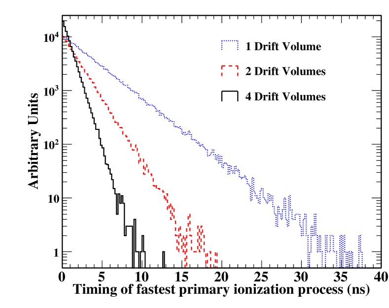
Micropattern detectors are characterised by a clear division of the various phases of the detection process, in particular the primary ionisation creation and drift is separated by the multiplication phase and so the gain of the signal. Thus, the time resolution is dominated by fluctuations of the nearest distance of the primary ionisation processes to the region where the gain is acquired, . Defining as the average number of primary clusters generated by an ionising particle inside the gas, this distance follows a classical exponential distribution . The drift velocity of the gas determines the arrival time, the exponential behaviour is shown in Fig. 1 and contribution of to the time resolution is
| (1) |
Both gas parameters depend mainly on the gas mixture used in the device and, in addition, is also a function of the electric field. Typical values for gases employed in MPGDs are and up to leading to few time resolution with the best choice of gas mixtures and operating voltages. By comparison, the contribution of the gain fluctuation is governed by the gas time constant , where is the effective Townsend coefficient. In the multiplication volume the field is very high () and consequently and with a resulting contribution to the time resolution much below .
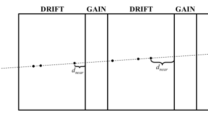
In order to improve the time resolution a new configuration is proposed and is shown in Fig. 2. The improvement is obtained by using several drift regions each one coupled to its multiplication stage, which is realised with a fully resistive WELL structure. In Fig. 1 results of a simulation are shown for configurations using up to four drift regions, which already demonstrate the benefit. The reduction of the time resolution, in fact, is proportional to the number of the layers employed, leading Eq. 1 to be modified as follows:
| (2) |
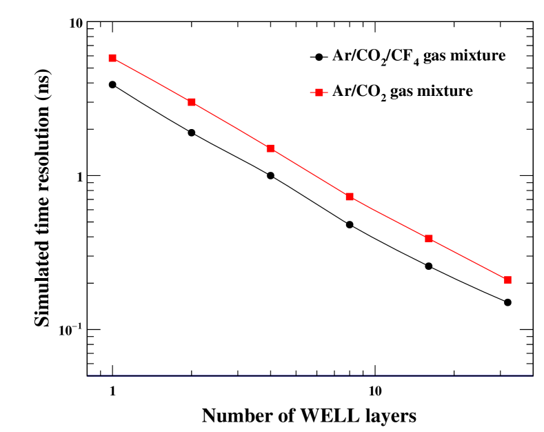
The behaviour is also evident in Fig. 3, where the results of a simulation of timing response, taking into account also the micro behaviour of the drift and avalanche formation with GARFIELD [14] is demonstrated.
3 The detector layout and test set-up
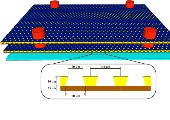
The detector layout of the prototype is based on the concept of the micro-Resistive WELL detector [7]: two layers are used for this first implementation, which is sketched in Fig. 4. The multiplication volume is based on of a pair of polyimide foils stacked due to the electrostatic force induced by the polarisation of the foils. The perforated foils are a thick Apical KANECA, which is initially coated with diamond-like carbon (DLC) techniques. This coating technique is used to provide, to the perforated polyimide foil, a potential gradient with resistive layers of the order of , replacing the copper coating. The holes are inverted truncated cones with the two bases of and diameter. The pitch between holes is of . The second foils are the thick XC Dupont Kapton, which have a resistivity of the order of . The drift volumes are thick. The planarity is ensured by a set of pillars obtained by PCB technique with photoimageable coverlay. The pillars’ diameter is with a pitch of . The spacing around the active region is ensured by the use of two -thick polyimide foils.
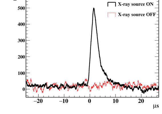
The employment of only resistive layers in the architecture allows signals coming from the layers to be externally extracted thanks to the resulting transparency of polarising electrodes. The prototype has been operated with a gas mixture. The different regions have been polarised with the CAEN N1470 power supply in order to give an electric field of for the drift regions and for the amplification regions for a gain between and . The signals from the readout electrode have been sent to the low-noise charge-sensitive ORTEC PC142 preamplifier. The resulting inverted signal outputs have been amplified by the ORTEC 474 NIM module and acquired with a Tektronix TDS 2024C oscilloscope. An X-ray source has been used in order to demonstrated the capability of signal extraction, and the results are shown in Fig. 5 where an average signal is shown in presence and absence of the source. This is the first signal coming from a FTM device allowing the implementation of the principles described in this paper. The detailed studies of the performance for this class of devices has started and will be the subject of future papers.
4 Conclusions and outlook
In this paper we have described a novel class of micropattern gaseous detectors for fast timing applications called the FTM. The construction feasibility has been demonstrated by building a first working prototype. We expect that this technique can be exploited for applications in high energy physics experiments, particularly for upgrades at LHC where sub nanosecond time resolutions are critical for particle identification and vertex separation. Other applications include X-ray diffraction studies and fast time-resolved measurements offer excellent medical imaging opportunities. In combination with an X-ray convertor and FTM and a visible photocathode shows great promise for use in digital mammography. Other applications include X-ray astronomy by exploiting time resolution of the FTM and selective sensitivity to soft X-rays. For further studies, the subject of future publications, we are building prototypes with several layers, and in parallel investigating larger size cost effective production techniques.
Acknowledgments
We are grateful to Silvia Franchino for assembling the device and assisting with the measurements.
References
- [1] A. Sharma, Muon tracking and triggering with gaseous detectors and some applications, Nucl. Instrum. Methods, A666, (2012) 98.
- [2] F. Sauli and A. Sharma, Micropattern Gaseous Detector, Annu. Rev. Nucl. Part. Sci., 49, (1999), 341.
- [3] M. Titov and L. Ropelewski, Micro-pattern gaseous detector technologies and RD51 Collaboration, Mod. Phys. Lett., A 28, (2013), 1340022.
- [4] , S. Bachmann et al., Discharge mechanisms and their prevention in the gas electron multiplier (GEM), Nucl. Instrum. Methods, A479, (2002), 294,
- [5] I. Giomataris et al., Micromegas: a high-granularity, position sensitive gaseous detector for high particle flux environments, Nucl. Instr. Methods, A 376, (1996), 29.
- [6] P. Fonte et al., Advances in the Development of Micropattern Gaseous Detectors with Resistive Electrodes, Nucl. Instr. Methods, A 661, (2012), 153.
- [7] G. Bencivenni et al., The micro-Resistive WELL detector: a compact spark-protected single amplification-stage MPGD”, JINST, 10, (2015), P02008.
- [8] F. Sauli and et al., rm GEM: A new concept for electron amplification in gas detectors, Nucl. Instr. Methods, A 386, (1997), 531.
- [9] F. Sauli, Discharge studies and prevention in the gas electron multiplier, CERN-EP/2000-151, (2000), 11.
- [10] M. Alfonsi et al., rm High-rate particle triggering with triple-GEM detector, Nucl. Instr. Methods, A 518, (2004), 106.
- [11] P. Everaerts Rate capability and ion feedback in GEM detectors, CERN-THESIS-2006-088, (2006).
- [12] D. Abbaneo et al., GEM based detector for future upgrade of the CMS forward muon system, Nucl. Instr. Methods, A 718, (2013), 383.
- [13] A. Balla et al., The cylindrical GEM detector for the KLOE-2 Inner Tracker, JINST, 9, (2014), C01014.
-
[14]
R. Veenhof, Garfield, recent development,
Nucl. Instr. Methods, A 419, (1998), 726.
– Garfield – A Simulation of gaseous detectors, http://cern.ch/garfield