Comparison of spin-orbit torques and spin pumping across NiFe/Pt and NiFe/Cu/Pt interfaces
Abstract
We experimentally investigate spin-orbit torques and spin pumping in NiFe/Pt bilayers with direct and interrupted interfaces. The damping-like and field-like torques are simultaneously measured with spin-torque ferromagnetic resonance tuned by a dc bias current, whereas spin pumping is measured electrically through the inverse spin Hall effect using a microwave cavity. Insertion of an atomically thin Cu dusting layer at the interface reduces the damping-like torque, field-like torque, and spin pumping by nearly the same factor of 1.4. This finding confirms that the observed spin-orbit torques predominantly arise from diffusive transport of spin current generated by the spin Hall effect. We also find that spin-current scattering at the NiFe/Pt interface contributes to additional enhancement in magnetization damping that is distinct from spin pumping.
I Introduction
Current-induced torques due to spin-orbit effects Brataas2014 ; Gambardella2011a ; Haney2013a potentially allow for more efficient control of magnetization than the conventional spin-transfer torques Ralph2008 ; Brataas2012a . The spin Hall effect Hoffmann2013 is reported to be the dominant source of spin-orbit torques in thin-film bilayers consisting of a ferromagnet (FM) interfaced with a normal metal (NM) with strong spin-orbit coupling. Of particular technological interest is the spin-Hall “damping-like” torque that induces magnetization switching Miron2011 ; Liu2012 ; Bhowmik2014 ; Yu2014b , domain-wall motion Haazen2013 ; Emori2014d ; Ryu2014 ; Ueda2014a , and high-frequency magnetization dynamics Demidov2012 ; Liu2012a ; Liu2013 ; Duan2014a ; Ranjbar2014 ; Hamadeh2014a . While this spin-Hall torque originates from spin-current generation within the bulk of the NM layer, the magnitude of the torque depends on the transmission of spin current across the FM/NM interface Haney2013a . Some FM/NM bilayers with 1-nm thick FM exhibit another spin-orbit torque that is phenomenologically identical to a torque from an external magnetic field Kim2013a ; Garello2013 ; Fan2013 ; Fan2014 ; Pai2014 ; Pai2014a ; Emori2014c ; Woo2014 . This “field-like” torque is also interface-dependent, because it may emerge from the Rashba effect at the FM/NM interface Gambardella2011a , or the nonadiabaticity Ralph2008 of spin-Hall-generated spin current transmitted across the interface Haney2013a ; Fan2013 ; Fan2014 ; Pai2014 .
To understand the influence of the FM/NM interface on magnetization dynamics, many studies have experimentally investigated resonance-driven spin pumping from FM to NM Tserkovnyak2002a ; Tserkovnyak2002 , detected with enhanced damping Ghosh2011 ; Boone2013 ; Boone2014 ; Heinrich2011 ; Sun2013a or dc voltage due to the inverse spin Hall effect Azevedo2005a ; Saitoh2006 ; Mosendz2010a ; Czeschka2011a ; Ando2011 ; Deorani2013 ; Weiler2014c ; Obstbaum2014 ; Rojas-Sanchez2014 ; Wang2014 . The parameter governing spin-current transmission across the FM/NM interface is the spin-mixing conductance (Ref. (46)). Simultaneously investigating spin pumping and spin-orbit torques, which are theoretically reciprocal effects Brataas2012a , should reveal the interface dependence of the observed torques in FM/NM.
Here we investigate spin-orbit torques and magnetic resonance in in-plane magnetized NiFe/Pt bilayers with direct and interrupted interfaces. To modify the NiFe/Pt interface, we insert an atomically thin dusting layer of Cu that does not exhibit strong spin-orbit effects by itself. We use spin-torque ferromagnetic resonance (ST-FMR) Sankey2007 ; Liu2011 combined with dc bias current to extract the damping-like and field-like torques simultaneously. We also independently measure the dc voltage generated by spin pumping across the FM/NM interface. The interfacial dusting reduces the damping-like torque, field-like torque, and spin pumping by the same factor. This finding is consistent with the diffusive spin-Hall mechanism Haney2013a ; Boone2013 of spin-orbit torques, where spin transfer between NM and FM depends on the interfacial spin-mixing conductance.
II Experimental Details
II.1 Samples
The two film stacks compared in this study are sub/Ta(3)/Ni80Fe20(2.5)/Pt(4) (“NiFe/Pt”) and sub/Ta(3)/Ni80Fe20(2.5)/Cu(0.5)/Pt(4) (“NiFe/Cu/Pt”), where the numbers in parentheses are nominal layer thicknesses in nm and sub is a Si(001) substrate with a 50-nm thick SiO2 overlayer. All layers were sputter-deposited at an Ar pressure of Torr with a background pressure of 1 Torr. The atomically thin dusting layer of Cu modifies the NiFe/Pt interface with minimal current shunting. The Ta seed layer facilitates the growth of thin NiFe with narrow resonance linewidth and near-bulk saturation magnetization Ghosh2011 ; Boone2014 .
We measured the saturation magnetization A/m for both NiFe/Pt and NiFe/Cu/Pt with vibrating sample magnetometry. From four-point measurements on various film stacks and assuming that individual constituent layers are parallel resistors, we estimate the resistivities of Ta(3), NiFe(2.5), Cu(0.5), and Pt(4) to be 240 cm, 90 cm, 60 cm, and 40 cm, respectively. Approximately 70% of the charge current thus flows in the Pt layer. In the subsequent analysis, we also include the small damping-like torque and the Oersted field from the highly resistive Ta layer (see Appendix A).
II.2 Spin-torque ferromagnetic resonance
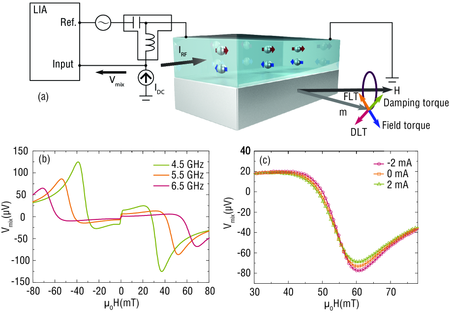
We fabricated 5-m wide, 25-m long microstrips of NiFe/Pt and NiFe/Cu/Pt with Cr/Au ground-signal-ground electrodes using photolithography and liftoff. We probed magnetization dynamics in the microstrips using ST-FMR (Refs. (47; 48)) as illustrated in Fig. 1(a): an rf current drives resonant precession of magnetization in the bilayer, and the rectified anisotropic magnetoresistance voltage generates an FMR spectrum. The rf current power output was +8 dBm and modulated with a frequency of 437 Hz to detect the rectified voltage using a lock-in amplifier. The ST-FMR spectrum (e.g., Fig. 1(b)) was acquired at a fixed rf driving frequency by sweeping an in-plane magnetic field mT applied at an angle from the current axis. The rectified voltage constituting the ST-FMR spectrum is fit to a Lorentzian curve of the form
| (1) |
where is the half-width-at-half-maximum resonance linewidth, is the resonance field, is the symmetric Lorentzian coefficient, and is the antisymmetric Lorentzian coefficient. Representative fits are shown in Fig. 1(c).
The lineshape of the ST-FMR spectrum, parameterized by the ratio of to in Eq. 1, has been used to evaluate the ratio of the damping-like torque to the net effective field from the Oersted field and field-like torque Liu2011 ; Kondou2012a ; Skinner2014 ; Wang2014c ; Mellnik2014 ; Pai2014a . To decouple the damping-like torque from the field-like torque, the magnitude of the rf current in the bilayer would need to be known Liu2011 ; Wang2014c . Other contributions to (Refs. (53; 54; 55)) may also affect the analysis based on the ST-FMR lineshape.
We use a modified approach where an additional dc bias current in the bilayer, illustrated in Fig. 1(a), transforms the ST-FMR spectrum as shown in Fig. 1(c). A high-impedance current source outputs , and we restrict mA (equivalent to the current density in Pt A/m2) to minimize Joule heating and nonlinear dynamics. The dependence of the resonance linewidth on allows for quantification of the damping-like torque Ando2008a ; Liu2011 ; Demidov2011 ; Pai2012 ; Ganguly2014 ; Kasai2014 ; Duan2014b ; Emori2015 , while the change in the resonance field yields a direct measure of the field-like torque Mellnik2014 . Thus, dc-tuned ST-FMR quantifies both spin-orbit torque contributions.
II.3 Electrical detection of spin pumping
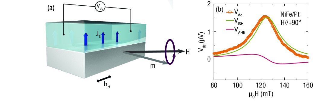
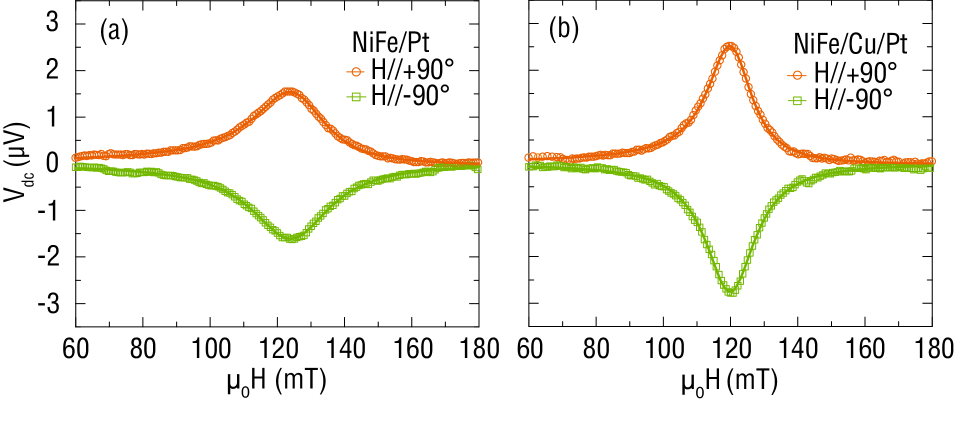
The inverse spin Hall voltage due to spin pumping was measured in 100-m wide, 1500-m long strips of NiFe/Pt and NiFe/Cu/Pt with Cr/Au electrodes attached on both ends, similar to the sub-mm wide strips used in Ref. (60). These NiFe/(Cu/)Pt strips were fabricated on the same substrate as the ST-FMR device sets described in Sec. II.2. The sample was placed in the center of a rectangular TE102 microwave cavity operated at a fixed rf excitation frequency of 9.55 GHz and rf power of 100 mW. A bias field was applied within the film plane and transverse to the long axis of the strip. The dc voltage across the sample was measured using a nanovoltmeter while sweeping the field, as illustrated in Fig. 2(a). The acquired spectrum is fit to Eq. 1 as shown by a representative result in Fig. 2(b). The inverse spin Hall voltage is defined as the amplitude of the symmetric Lorentzian coefficient in Eq. 1 (Refs. (38; 39; 40; 41; 44)). We note that the antisymmetric Lorentzian coefficient is substantially smaller, indicating that the voltage signal from the inverse spin Hall effect dominates over that from the anomalous Hall effect.
III Results and Analysis
III.1 Magnetic resonance properties
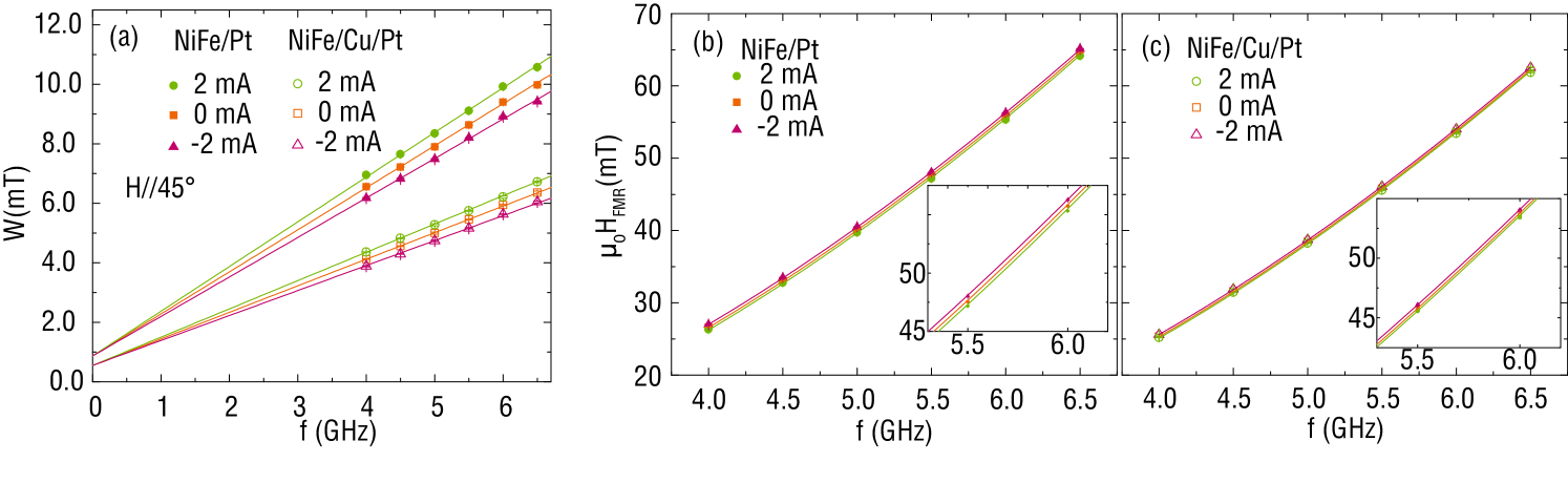
Fig. 3(a) shows the plot of the ST-FMR linewidth as a function of frequency for NiFe/Pt and NiFe/Cu/Pt at and mA. The Gilbert damping parameter is calculated for each sample in Fig. 3(a) from
| (2) |
where is the inhomogeneous linewidth broadening, is the frequency, and is the gyromagnetic ratio. With the Landé g-factor for NiFe (Refs. (61; 31; 42; 33)), (28.0 GHz/T) GHz/T. From the slope in Fig. 3(a) at , for NiFe/Pt and for NiFe/Cu/Pt. The reduction in damping with interfacial Cu-dusting is consistent with prior studies on FM/Pt with nm-thick Cu insertion layers Weiler2014c ; Ghosh2011 ; Boone2014 ; Rojas-Sanchez2014 ; Sun2013a .
A fit of versus frequency at to the Kittel equation
| (3) |
shown in Figs. 3(b),(c), gives the effective magnetization A/m for NiFe/Pt and A/m for NiFe/Cu/Pt, with the in-plane anisotropy field mT. and are indistinguishable within experimental uncertainty, implying negligible perpendicular magnetic anisotropy in NiFe/(Cu/)Pt.
When , the linewidth is reduced for one current polarity and enhanced for the opposite polarity, as shown in Fig. 3(a). The empirical damping parameter defined by Eq. 2 changes with (see Appendix B), which indicates the presence of a current-induced damping-like torque. Similarly, generates an Oersted field and a spin-orbit field-like torque that together shift the resonance field as shown in Figs. 3(b),(c). We discuss the quantification of the damping-like torque in Sec. III.2 and the field-like torque in Sec. III.5.
III.2 Damping-like torque
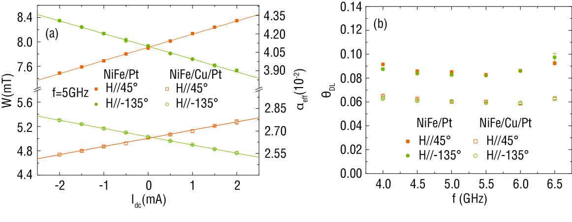
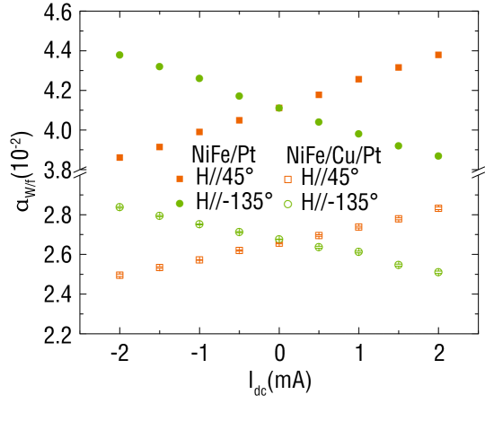
Fig. 4(a) shows the linear change in as a function of at a fixed rf frequency of 5 GHz. Reversing the external field (from to -135°) magnetizes the sample in the opposite direction and reverses the polarity of the damping-like torque.
is related to the current-dependent effective damping parameter at fixed , . The magnitude of the damping-like torque is parameterized by the effective spin Hall angle , proportional to the ratio of the spin current density crossing the FM/NM interface to the charge current density in Pt. at each frequency, plotted in Fig. 4(b), is calculated from the dependence of (Refs. (62; 48)):
| (4) |
where is the FM thickness. Assuming that the effective spin Hall angle is independent of frequency, we find for NiFe/Pt and for NiFe/Cu/Pt. These values are similar to recently reported in NiFe/Pt bilayers Czeschka2011a ; Weiler2014c ; Liu2011 ; Wang2014c ; Ganguly2014 ; Kasai2014 ; Ando2008a ; Duan2014b .
of NiFe/(Cu/)Pt is related to the intrinsic spin Hall angle of Pt through the spin diffusion theory used in Refs. (32; 3). For a Pt layer much thicker than its spin diffusion length , is proportional to the real part of the effective spin-mixing conductance ,
| (5) |
where is the conductivity of the Pt layer and includes the spin-current backflow factor Tserkovnyak2002 ; Boone2013 . Assuming that , , and in Eq. 5 are independent of the interfacial Cu dusting layer, is a factor of greater for NiFe/Pt than NiFe/Cu/Pt based on the values of found above.
III.3 Reciprocity of damping-like torque and spin pumping
Fig. 5 shows representative results of the dc inverse spin Hall voltage induced by spin pumping, each fitted to the Loretzian curve defined by Eq. 1. Reversing the bias field reverses the moment orientation of the pumped spin current and thus inverts the polarity of , consistent with the mechanism of the inverse spin Hall effect. By averaging measurements at opposite bias field polarities for different samples, we find V for NiFe/Pt and V for NiFe/Cu/Pt.
The inverse spin Hall voltage is given by Mosendz2010a
| (6) |
where is the sheet resistance of the sample, is the length of the sample, is the ellipticity parameter of magnetization precession, and is the amplitude of the microwave excitation field. The factor is equal to the precession cone angle at resonance in the linear (small angle) regime. By collecting all the factors in Eq. 6 that are identical for NiFe/Pt and NiFe/Cu/Pt into a single coefficient , Eq. 6 is rewritten as
| (7) |
We note that the small difference in for NiFe/Pt and NiFe/Cu/Pt yields a difference in (Eq. 6) of 1%, which we neglect here.
From Eq. 7, we estimate that of the NiFe/Pt interface is greater than that of the NiFe/Cu/Pt interface by a factor of . The dc-tuned ST-FMR and dc spin-pumping voltage measurements therefore yield quantitatively consistent results, confirming the reciprocity between the damping-like torque (driven by the direct spin Hall effect) and spin pumping (detected with the inverse spin Hall effect). The fact that the diffusive model captures the observations supports the spin-Hall mechanism leading to the damping-like torque.
III.4 Interfacial damping and spin-current transmission
Provided that the enhanced damping in NiFe/(Cu/)Pt (Fig. 3(a)) is entirely due to spin pumping into the Pt layer, the real part of the interfacial spin-mixing conductance can be calculated by
| (8) |
Using measured for a reference film stack sub/Ta(3)/NiFe(2.5)/Cu(2.5)/TaOx(1.5) with negligible spin pumping into the top NM layer of Cu, we obtain Re m-2 for NiFe/Pt and m-2 for NiFe/Cu/Pt. This factor of 2 difference for the two interfaces is significantly greater than the factor of 1.4 determined from dc-tuned ST-FMR (Sec. III.2) and electrically detected spin pumping (Sec. III.3). This discrepancy implies that the magnitude of Re of NiFe/Pt calculated from enhanced damping is higher than that calculated for spin injection.
In addition to spin pumping, interfacial scattering effects Rojas-Sanchez2014 ; Nguyen2014 ; Park2000 ; Liu2014c , e.g., due to proximity-induced magnetization in Pt Sun2013a ; Ryu2014 ; Lim2013 or spin-orbit phenomena at the NiFe/Pt interface Nembach2014 , may contribute to both stronger damping and lower spin injection in NiFe/Pt. Assuming that this interfacial scattering is suppressed by the Cu dusting layer, 0.010 of in NiFe/Pt is not accounted for by spin pumping. The corrected Re for NiFe/Pt is m-2, which is in excellent agreement with Re calculated from first principles Liu2014c .
Using quantified above and assuming nm Boone2013 ; Boone2014 ; Kondou2012a ; Ganguly2014 ; Kasai2014 ; Pai2014a ; Obstbaum2014 ; Skinner2014 ; Wang2014c , the intrinsic spin Hall angle of Pt and the spin-current transmissivity across the FM/NM interface can be estimated. We obtain , and for NiFe/Pt and for NiFe/Cu/Pt. These results, in line with a recent report Pai2014a , indicate that the damping-like torque (proportional to ) may be increased by engineering the FM/NM interface, i.e., by increasing . For practical applications, the threshold charge current density required for switching or self-oscillation of the magnetization is proportional to the ratio . Because of the reciprocity of the damping-like torque and spin pumping, increasing would also increase such that it would cancel the benefit of enhancing . Nevertheless, although spin pumping inevitably increases damping, optimal interfacial engineering might minimize damping from interfacial spin-current scattering while maintaining efficient spin-current transmission across the FM/NM interface.
III.5 Field-like torque
We now quantify the field-like torque from the dc-induced shift in the resonance field , derived from the fit to Eq. 3, as shown in Figs. 3(b),(c). is fixed at its zero-current value so that is the only free parameter 111When is adjustable changes only by 1%.. Fig. 6 shows the net current-induced effective field, which is equivalent to in our experimental geometry with the external field applied 45∘ from the current axis. The solid lines show the expected Oersted field mT per mA for both NiFe/Pt and NiFe/Cu/Pt based on the estimated charge current densities in the NM layers, , where the contribution from the Pt layer dominates by a factor of 6.
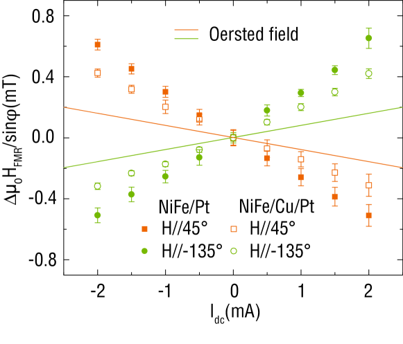
While the polarity of the shift in is consistent with the direction of , the magnitude of exceeds for both samples as shown in Fig. 6. This indicates the presence of an additional current-induced effective field due to a field-like torque, mT per mA for NiFe/Pt and mT per mA for NiFe/Cu/Pt. Analogous to for the damping-like torque, the field-like torque can also be parameterized by an effective spin Hall angle Pai2014a :
| (9) |
Eq. 9 yields for NiFe/Pt and for NiFe/Cu/Pt, comparable to recently reported results in Ref. (23).
The ultrathin Cu layer at the NiFe/Pt interface reduces the field-like torque by a factor of , which is in agreement within experimental uncertainty to the reduction of the damping-like torque (Sec. III.2). This suggests that both torques predominantly originate from the spin Hall effect in Pt. Recent studies on FM/NM bilayers using low-frequency measurement techniques Fan2013 ; Fan2014 ; Pai2014 also suggest that the spin Hall effect is the dominant source of the field-like torque. Since the field-like torque scales as the imaginary component of (Refs. (3; 4; 5)), the Cu dusting layer must modify Re[] and Im[] identically. We estimate to be m-2 for NiFe/Pt and m-2 for NiFe/Cu/Pt.
Because of the relatively large error bar for the ratio of the field-like torque in NiFe/Pt and NiFe/Cu/Pt, our experimental results do not rule out the existence of another mechanism at the FM/NM interface, distinct from the spin Hall effect. For example, the Cu dusting layer may modify the interfacial Rashba effect that can be an additional contribution to the field-like torque Gambardella2011a ; Haney2013a ; Fan2014 . Also, the upper bound of the field-like torque ratio is close to the factor of 2 reduction in damping with Cu insertion, possibly suggesting a correlation between the spin-orbit field-like torque and the enhancement in damping at the FM-NM interface. Elucidating the exact roles of interfacial spin-orbit effects in FM/HM requires further theoretical and experimental studies.
III.6 Comparison of the dc-tuned and lineshape methods of ST-FMR
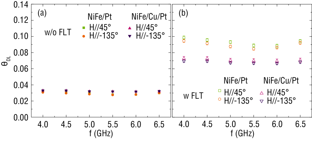
Accounting for the field-like torque, we determine the effective spin Hall angle in NiFe/Pt and NiFe/Cu/Pt from the lineshape (Eq. 1) of the ST-FMR spectra at (Refs. (48; 49; 50; 51; 52; 26)). The coefficients in Eq. 1 are and , where is the ST-FMR voltage prefactor Liu2011 and is the net effective rf magnetic field generated by the rf driving current density in the Pt layer. is calculated from the lineshape coefficients and :
| (10) |
Fig. 7(a) shows obtained by ignoring the field-like torque contribution, i.e., . This underestimates , implying identical damping-like torques in NiFe/Pt and NiFe/Cu/Pt. Using extracted from Fig. 6, for NiFe/Pt and for NiFe/Cu/Pt plotted in Fig. 7(b) are in agreement with determined from the dc-tuned ST-FMR method. The presence of a nonnegligible field-like torque in thin FM may account for the underestimation of based on the lineshape analysis compared to from dc-tuned ST-FMR as reported in Refs. (54; 55).
| NiFe/Pt | NiFe/Cu/Pt | |
|---|---|---|
| ( m-2) | ||
| ( m-2) | ||
| (a.u.) | ||
IV Conclusions
We have experimentally demonstrated that the spin-orbit damping-like and field-like torques scale with interfacial spin-current transmission. Insertion of an ultrathin Cu layer at the NiFe/Pt interface equally reduces the spin-Hall-mediated spin-orbit torques and spin pumping, consistent with diffusive transport of spin current across the FM/NM interface. Parameters relevant to spin-orbit torques in NiFe/Pt and NiFe/Cu/Pt quantified in this work are summarized in Table 1. We have also found an additional contribution to damping at the NiFe/Pt interface distinct from spin pumping. The dc-tuned ST-FMR technique used here permits precise quantification of spin-orbit torques directly applicable to engineering efficient spin-current-driven devices.
Acknowledgements
T.N. and S.E. contributed equally to this work. This work was supported by the Air Force Research Laboratory through contract FA8650-14-C-5706 and in part by FA8650-14-C-5705, the W.M. Keck Foundation, and the National Natural Science Foundation of China (NSFC) 51328203. Lithography was performed in the George J. Kostas Nanoscale Technology and Manufacturing Research Center. S.E. thanks Xin Fan and Chi-Feng Pai for helpful discussions. T.N. and S.E. thank James Zhou and Brian Chen for assistance in setting up the ST-FMR system, and Vivian Sun for assistance in graphic design.
Appendix A: Damping-like torque contribution from Tantalum
With the same dc-tuned ST-FMR technique described in Sec. II.2, we evaluate the effective spin Hall angle of Ta interfaced with NiFe. Because of the high resistivity of Ta, the signal-to-noise ratio of the ST-FMR spectrum is significantly lower than in the case of NiFe/Pt, thus making precise determination of more challenging. Nevertheless, we are able to obtain an estimate of from a 2-m wide, 10-m long strip of subs/Ta(6 nm)/Ni80Fe20(4 nm)/Al2O3(1.5 nm) (“Ta/NiFe”) . The estimated resistivity of Ta(6 nm) is 200 cm and that of NiFe(4 nm) is 70 cm.
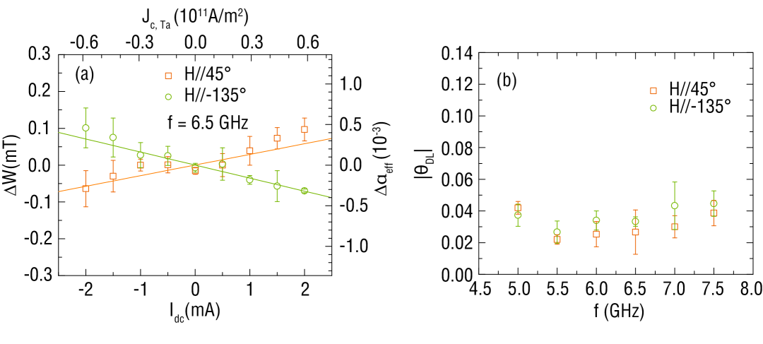
Fig. 8(a) shows the change in linewidth (or ) due to dc bias current . The polarity of against is the same as in NiFe capped with Pt (Fig. 4(a)). Because the Ta layer is beneath the NiFe layer, this observed polarity is consistent with the opposite signs of the spin Hall angles for Pt and Ta. Here we define the sign of for Ta/NiFe to be negative. Using Eq. 4 with A/m and averaging the values plotted in Fig. 8(b), we arrive at . This magnitude of is substantially smaller than in Ta/CoFe(B) Liu2012 ; Emori2014d and Ta/FeGaB Emori2015 , but similar to reported values of in Ta/NiFe bilayers Weiler2014c ; Deorani2013 . For the analysis of the damping-like torque in Sec. III.2, we take into account the obtained above and the small charge current density in Ta. In the Ta/NiFe/(Cu/)/Pt stacks, owing to the much higher conductivity of Pt, the spin-Hall damping-like torque from the top Pt(4) layer is an order of magnitude greater than the torque from the bottom Ta(3) seed layer.
Appendix B: dc dependence of the empirical damping parameter
Magnetization dynamics in the presence of an effective field and a damping-like spin torque is given by the Landau-Lifshitz-Gilbert-Slonczewski equation:
| (11) |
where is a coefficient for the damping-like torque (proportional to ) and is the orientation of the spin moment entering the FM. Within this theoretical framework, it is not possible to come up with a single Gilbert damping parameter as a function of bias dc current that holds at all frequencies. However, at we empirically extract the damping parameter from the linear relationship of linewidth versus frequency (Eq. 2). We can take the same approach and define an empirical damping parameter as a function of , i.e.
| (12) |
where we fix the inhomogeneous linewidth broadening at the value at , which does not change systematically as a function of small used here. This approach of setting as the only fitting parameter in Eq. 12 well describes our data (e.g., Fig. 3(a)). We show in Fig. 9 the resulting versus . The change in normalized by the charge current density in Pt is per A/m2 for NiFe/Pt and per A/m2 for NiFe/Cu/Pt. This empirical measure of the damping-like torque again exhibits a factor of 1.4 difference between NiFe/Pt and NiFe/Cu/Pt.
References
- (1) A. Brataas and K. M. D. Hals, Nat. Nanotechnol. 9, 86 (2014).
- (2) P. Gambardella and I. M. Miron, Philos. Trans. A. Math. Phys. Eng. Sci. 369, 3175 (2011).
- (3) P. M. Haney, H.-W. Lee, K.-J. Lee, A. Manchon, and M. D. Stiles, Phys. Rev. B 87, 174411 (2013).
- (4) D. Ralph and M. Stiles, J. Magn. Magn. Mater. 320, 1190 (2008).
- (5) A. Brataas, Y. Tserkovnyak, G. E. W. Bauer, and P. J. Kelly, Spin pumping and spin transfer, in Spin Current, chap. 8, pp. 87–135, 2012.
- (6) A. Hoffmann, IEEE Trans. Magn. 49, 5172 (2013).
- (7) I. M. Miron, K. Garello, G. Gaudin, P.-J. Zermatten, M. V. Costache, S. Auffret, S. Bandiera, B. Rodmacq, A. Schuhl, and P. Gambardella, Nature 476, 189 (2011).
- (8) L. Liu, C.-F. Pai, Y. Li, H. W. Tseng, D. C. Ralph, and R. A. Buhrman, Science 336, 555 (2012).
- (9) D. Bhowmik, L. You, and S. Salahuddin, Nat. Nanotechnol. 9, 59 (2014).
- (10) G. Yu, P. Upadhyaya, Y. Fan, J. G. Alzate, W. Jiang, K. L. Wong, S. Takei, S. A. Bender, L.-T. Chang, Y. Jiang, M. Lang, J. Tang, Y. Wang, Y. Tserkovnyak, P. K. Amiri, and K. L. Wang, Nat. Nanotechnol. 9, 548 (2014).
- (11) P. P. J. Haazen, E. Murè, J. H. Franken, R. Lavrijsen, H. J. M. Swagten, and B. Koopmans, Nat. Mater. 12, 299 (2013).
- (12) S. Emori, E. Martinez, K.-J. Lee, H.-W. Lee, U. Bauer, S.-M. Ahn, P. Agrawal, D. C. Bono, and G. S. D. Beach, Phys. Rev. B 90, 184427 (2014).
- (13) K.-S. Ryu, S.-H. Yang, L. Thomas, and S. S. P. Parkin, Nat. Commun. 5, 3910 (2014).
- (14) K. Ueda, K.-J. Kim, Y. Yoshimura, R. Hiramatsu, T. Moriyama, D. Chiba, H. Tanigawa, T. Suzuki, E. Kariyada, and T. Ono, Appl. Phys. Express 7, 053006 (2014).
- (15) V. E. Demidov, S. Urazhdin, H. Ulrichs, V. Tiberkevich, A. Slavin, D. Baither, G. Schmitz, and S. O. Demokritov, Nat. Mater. 11, 1028 (2012).
- (16) L. Liu, C.-F. Pai, D. C. Ralph, and R. A. Buhrman, Phys. Rev. Lett. 109, 186602 (2012).
- (17) R.H. Liu, W.L. Lim, and S. Urazhdin, Phys. Rev. Lett. 110, 147601 (2013).
- (18) Z. Duan, A. Smith, L. Yang, B. Youngblood, J. Lindner, V. E. Demidov, S. O. Demokritov, and I. N. Krivorotov, Nat. Commun. 5, 5616 (2014).
- (19) M. Ranjbar, P. Durrenfeld, M. Haidar, E. Iacocca, M. Balinskiy, T. Q. Le, M. Fazlali, A. Houshang, A. Awad, R. Dumas, and J. Akerman, IEEE Magn. Lett. 5, 1 (2014).
- (20) A. Hamadeh, O. d’Allivy Kelly, C. Hahn, H. Meley, R. Bernard, A. H. Molpeceres, V. V. Naletov, M. Viret, A. Anane, V. Cros, S. O. Demokritov, J. L. Prieto, M. Muñoz, G. de Loubens, and O. Klein, Phys. Rev. Lett. 113, 197203 (2014).
- (21) J. Kim, J. Sinha, M. Hayashi, M. Yamanouchi, S. Fukami, T. Suzuki, S. Mitani, and H. Ohno, Nat. Mater. 12, 240 (2013).
- (22) K. Garello, I. M. Miron, C. O. Avci, F. Freimuth, Y. Mokrousov, S. Blügel, S. Auffret, O. Boulle, G. Gaudin, and P. Gambardella, Nat. Nanotechnol. 8, 587 (2013).
- (23) X. Fan, J. Wu, Y. Chen, M. J. Jerry, H. Zhang, and J. Q. Xiao, Nat. Commun. 4, 1799 (2013).
- (24) X. Fan, H. Celik, J. Wu, C. Ni, K.-J. Lee, V. O. Lorenz, and J. Q. Xiao, Nat. Commun. 5, 3042 (2014).
- (25) C.-F. Pai, M.-H. Nguyen, C. Belvin, L. H. Vilela-Leão, D. C. Ralph, and R. A. Buhrman, Appl. Phys. Lett. 104, 082407 (2014).
- (26) C.-F. Pai, Y. Ou, D. C. Ralph, and R. A. Buhrman, (2014), arXiv:1411.3379.
- (27) S. Emori, U. Bauer, S. Woo, and G. S. D. Beach, Appl. Phys. Lett. 105, 222401 (2014).
- (28) S. Woo, M. Mann, A. J. Tan, L. Caretta, and G. S. D. Beach, Appl. Phys. Lett. 105, 212404 (2014).
- (29) Y. Tserkovnyak, A. Brataas, and G. E. W. Bauer, Phys. Rev. Lett. 88, 117601 (2002).
- (30) Y. Tserkovnyak, A. Brataas, and G. E. W. Bauer, Phys. Rev. B 66, 224403 (2002).
- (31) A. Ghosh, J. F. Sierra, S. Auffret, U. Ebels, and W. E. Bailey, Appl. Phys. Lett. 98, 052508 (2011).
- (32) C. T. Boone, H. T. Nembach, J. M. Shaw, and T. J. Silva, J. Appl. Phys. 113, 153906 (2013).
- (33) C. T. Boone, J. M. Shaw, H. T. Nembach, and T. J. Silva, (2014), arXiv:1408.5921.
- (34) B. Heinrich, C. Burrowes, E. Montoya, B. Kardasz, E. Girt, Y.-Y. Song, Y. Sun, and M. Wu, Phys. Rev. Lett. 107, 066604 (2011).
- (35) Y. Sun, H. Chang, M. Kabatek, Y.-Y. Song, Z. Wang, M. Jantz, W. Schneider, M. Wu, E. Montoya, B. Kardasz, B. Heinrich, S. G. E. te Velthuis, H. Schultheiss, and A. Hoffmann, Phys. Rev. Lett. 111, 106601 (2013).
- (36) A. Azevedo, L. H. Vilela Leão, R. L. Rodriguez-Suarez, A. B. Oliveira, and S. M. Rezende, J. Appl. Phys. 97, 10C715 (2005).
- (37) E. Saitoh, M. Ueda, H. Miyajima, and G. Tatara, Appl. Phys. Lett. 88, 182509 (2006).
- (38) O. Mosendz, V. Vlaminck, J. E. Pearson, F. Y. Fradin, G. E. W. Bauer, S. D. Bader, and A. Hoffmann, Phys. Rev. B 82, 214403 (2010).
- (39) F. D. Czeschka, L. Dreher, M. S. Brandt, M. Weiler, M. Althammer, I.-M. Imort, G. Reiss, A. Thomas, W. Schoch, W. Limmer, H. Huebl, R. Gross, and S. T. B. Goennenwein, Phys. Rev. Lett. 107, 046601 (2011).
- (40) K. Ando, S. Takahashi, J. Ieda, Y. Kajiwara, H. Nakayama, T. Yoshino, K. Harii, Y. Fujikawa, M. Matsuo, S. Maekawa, and E. Saitoh, J. Appl. Phys. 109, 103913 (2011).
- (41) P. Deorani and H. Yang, Appl. Phys. Lett. 103, 232408 (2013).
- (42) M. Weiler, J. M. Shaw, H. T. Nembach, and T. J. Silva, IEEE Magn. Lett. 5, 1 (2014).
- (43) M. Obstbaum, M. Härtinger, H. G. Bauer, T. Meier, F. Swientek, C. H. Back, and G. Woltersdorf, Phys. Rev. B 89, 060407 (2014).
- (44) J.-C. Rojas-Sánchez, N. Reyren, P. Laczkowski, W. Savero, J.-P. Attané, C. Deranlot, M. Jamet, J.-M. George, L. Vila, and H. Jaffrès, Phys. Rev. Lett. 112, 106602 (2014).
- (45) H. L. Wang, C. H. Du, Y. Pu, R. Adur, P. C. Hammel, and F. Y. Yang, Phys. Rev. Lett. 112, 197201 (2014).
- (46) A. Brataas, Y. V. Nazarov, and G. E. W. Bauer, Phys. Rev. Lett. 84, 2481 (2000).
- (47) J. C. Sankey, Y.-T. Cui, J. Z. Sun, J. C. Slonczewski, R. A. Buhrman, and D. C. Ralph, Nat. Phys. 4, 67 (2007).
- (48) L. Liu, T. Moriyama, D. C. Ralph, and R. A. Buhrman, Phys. Rev. Lett. 106, 036601 (2011).
- (49) K. Kondou, H. Sukegawa, S. Mitani, K. Tsukagoshi, and S. Kasai, Appl. Phys. Express 5, 073002 (2012).
- (50) T. D. Skinner, M. Wang, A. T. Hindmarch, A. W. Rushforth, A. C. Irvine, D. Heiss, H. Kurebayashi, and A. J. Ferguson, Appl. Phys. Lett. 104, 062401 (2014).
- (51) Y. Wang, P. Deorani, X. Qiu, J. H. Kwon, and H. Yang, Appl. Phys. Lett. 105, 152412 (2014).
- (52) A. R. Mellnik, J. S. Lee, A. Richardella, J. L. Grab, P. J. Mintun, M. H. Fischer, A. Vaezi, A. Manchon, E.-A. Kim, N. Samarth, and D. C. Ralph, Nature 511, 449 (2014).
- (53) A. Yamaguchi, H. Miyajima, T. Ono, Y. Suzuki, S. Yuasa, A. Tulapurkar, and Y. Nakatani, Appl. Phys. Lett. 90, 182507 (2007).
- (54) A. Ganguly, K. Kondou, H. Sukegawa, S. Mitani, S. Kasai, Y. Niimi, Y. Otani, and A. Barman, Appl. Phys. Lett. 104, 072405 (2014).
- (55) S. Kasai, K. Kondou, H. Sukegawa, S. Mitani, K. Tsukagoshi, and Y. Otani, Appl. Phys. Lett. 104, 092408 (2014).
- (56) K. Ando, S. Takahashi, K. Harii, K. Sasage, J. Ieda, S. Maekawa, and E. Saitoh, Phys. Rev. Lett. 101, 036601 (2008).
- (57) V. E. Demidov, S. Urazhdin, E. R. J. Edwards, and S. O. Demokritov, Appl. Phys. Lett. 99, 172501 (2011).
- (58) C.-F. Pai, L. Liu, Y. Li, H. W. Tseng, D. C. Ralph, and R. A. Buhrman, Appl. Phys. Lett. 101, 122404 (2012).
- (59) Z. Duan, C. T. Boone, X. Cheng, I. N. Krivorotov, N. Reckers, S. Stienen, M. Farle, and J. Lindner, Phys. Rev. B 90, 024427 (2014).
- (60) S. Emori, T. Nan, T. M. Oxholm, C. T. Boone, J. G. Jones, B. M. Howe, G. J. Brown, D. E. Budil, and N. X. Sun, Appl. Phys. Lett. 106, 022406 (2015).
- (61) S. Mizukami, Y. Ando, and T. Miyazaki, Phys. Rev. B 66, 104413 (2002).
- (62) S. Petit, C. Baraduc, C. Thirion, U. Ebels, Y. Liu, M. Li, P. Wang, and B. Dieny, Phys. Rev. Lett. 98, 077203 (2007).
- (63) H. Nguyen, W. P. Pratt, and J. Bass, J. Magn. Magn. Mater. 361, 30 (2014).
- (64) W. Park, D. V. Baxter, S. Steenwyk, I. Moraru, W. P. Pratt, and J. Bass, Phys. Rev. B 62, 1178 (2000).
- (65) Y. Liu, Z. Yuan, R. J. H. Wesselink, A. A. Starikov, and P. J. Kelly, Phys. Rev. Lett. 113, 207202 (2014).
- (66) W. L. Lim, N. Ebrahim-Zadeh, J. C. Owens, H. G. E. Hentschel, and S. Urazhdin, Appl. Phys. Lett. 102, 162404 (2013).
- (67) H. T. Nembach, J. M. Shaw, M. Weiler, E. Jué, and T. J. Silva, (2014), arXiv:1410.6243.
- (68) When is adjustable changes only by 1%.