Control of Dzyaloshinskii-Moriya interaction in Mn1-xFexGe: a first-principles study
Abstract
Motivated by the recent experiment on the size and helicity control of skyrmions in Mn1-xFexGe [K. Shibata et al., Nature Nanotechnology 8, 732 (2013)], we study how the Dzyaloshinskii-Moriya (DM) interaction changes its size and sign in metallic helimagnets. By means of first-principles calculations, we successfully reproduce the non-trivial sign change of the DM interaction observed in the experiment. While the DM interaction sensitively depends on the carrier density or the detail of the electronic structure such as the size of the exchange splitting, its behavior can be systematically understood in terms of the distribution of anticrossing points in the band structure. By following this guiding principle, we can even induce gigantic anisotropy in the DM interaction by applying a strain to the system. These results pave the new way for skyrmion crystal engineering in metallic helimagnets.
A skyrmion is a topologically protected nano-size spin texture found in several magnetsbogdanov1989 ; rossler2006 ; muhlbauer2009 ; yu2010 ; yu2011 . Due to its unusual spin structure, many intriguing behaviors such as topological Hall effects, current-driven motion, and multiferroic behavior have been observednagaosa2013 . Although there is a huge potential to design novel functional materials by exploiting these unique electromagnetic properties, skyrmion engineering or skyrmion-crystal engineering is yet to be established. Here, the key issue is how to manipulate the size and helicity of skyrmions. Regarding this problem, a recent experiment for the representative skyrmion system Mn1-xFexGe has shown that we can tune the skyrmion size and helicity by changing the carrier densityshibata2013 ; grigoriev2013 .
The Hamiltonian which determines the nature of skyrmions is
| (1) |
where is the magnetization per volume, is the Dzyaloshinskii-Moriya (DM) interaction coefficient and is the ferromagnetic exchange coupling, respectively. For materials design of skyrmion crystals, we need to know the precise value of . However, non-empirical evaluation of these parameters in the classical continuum model has been a difficult challenge, since it requires an elaborate multi-scale approach spanning the quantum to classical regime. For the insulating skyrmion system Cu2OSeO3seki2012 , there is a work in which the spin Hamiltonian (1) was derived from first principlesjanson2014 . By comparing the total energy of various magnetic states, they determined the value of , and succeeded in reproducing the experimentally measured skyrmion size. However, the guiding principle to control the values of is yet to be obtained.
On the other hand, for metallic systems, the situation is different. There are several studies for the estimate of heide2008 ; ferriani2008 ; heide2009 ; udvardi2003 ; ebert2009 ; katsnelson2010 ; dmitrienko2014 ; freimuth2013 ; freimuth2014 ; wakatsuki2014 . Among them, recently, one of the present authors (NN) and his collaborators have shown that the DM interaction in the two-band model drastically changes when the band anticrossing point resides near the Fermi levelwakatsuki2014 . The story is analogous to that of anomalous Hall conductivity, in which the band anticrossings act as magnetic monopoles in momentum spacenagaosa2010 . In Ref. freimuth2014, , a Berry phase expression for the DM interaction has also been formulated. These studies stimulate us to explore a fascinating possibility of controlling the DM interaction in metallic systems by manipulating the electronic structure. Indeed, the fact that not only the size but also the helicity of skyrmions in Mn1-xFexGe changes as a function of indicates that we have a good chance to control the value of .
In this paper, we show a quantitative analysis of the DM interaction in the metallic helimagnet, Mn1-xFexGe, based on ab initio density-functional theory (DFT) calculation.
From the obtained band structure, we evaluate the off-diagonal spin susceptibility which is a direct measure of the DM interaction.
We find that the sign change of observed in the experiment for Mn1-xFexGe is successfully reproduced.
The carrier-density dependence of can be systematically understood in terms of the distribution of band anti-crossing points in the electronic structure.
We demonstrate that the sign and the size of can be controlled as a function of the carrier density or the size of the exchange splitting.
There is also an interesting possibility to induce gigantic anisotropy in by applying a strain to the system.
Results
DM interaction in the continuum model.
Let us first look at the second term in the Hamiltonian (1).
This indicates that -linear term in the spin susceptibility, , should be proportional to the DM interaction coefficient, .
Therefore, to estimate in the continuum limit from the DFT calculation, we compute the long-wave length limit of the spin susceptibility, that is,
| (2) |
Here, or and corresponds to the coefficient for in Eq. (1). Since we consider the skyrmions in the - plane under the total magnetic moment along the -axis, hereafter we focus on and . In Eq. (2), we use the non-interacting spin susceptibility defined as
| (3) |
where, is the Pauli matrix and is the non-interacting Green’s function in the orbital basis. Using this non-interacting spin susceptibility, we can write as with
| (4) |
where is the eigenvector of the Kohn-Sham Hamiltonian with the eigenvalue of .
Hence, we can discuss the DM interaction in terms of the band structure.
Although there is a sophisticated approach to compute freimuth2014 , we employ the current simple approach to explore various parameters and materials.
Furthermore, this approach is appropriate to obtain a guiding principle for controlling as discussed below.
Ab initio band structure.
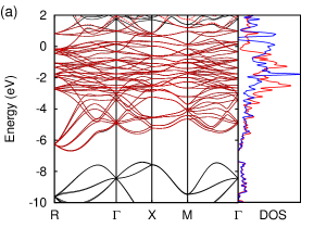
Figure 1(a) shows the DFT band structure of FeGe (black solid lines).
Here, we include the spin-orbit couplings and assume the ferromagnetic moment along the axis.
The calculated local magnetic moment is 1.18 per Fe atom, which is consistent with the experimentswappling1968 ; lundgren1968 and previous calculationsyamada2003 .
Using this electronic structure, we construct the tight-binding model made of Fe 3d and Ge 4p Wannier orbitals to reproduce the band structure below the Fermi level as shown in red broken lines.
The densities of states for up spin (red line) and down spin (blue line) are also shown in Fig. 1(a).
As can be seen, there is a large exchange splitting, .
According to the energy difference of up and down spins for the Fe 3d orbitals, we obtain eV.
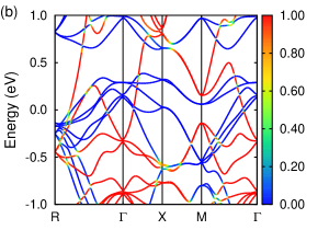
In Fig. 1(b), the obtained tight-binding band structure around the Fermi level is illustrated with colors representing the weight of the up spin.
Since we consider ferromagnetic electronic structure, each band can be basically characterized as either up-spin or down-spin band as shown in Fig. 1(b).
In addition, due to the spin-orbit couplings, there are several anticrossing points where complex spin texture emerges.
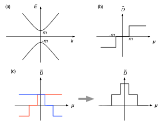

Ab initio evaluation of the DM interaction. Let us start with the simple two-band model in two dimensions considered in Ref. wakatsuki2014, . The Hamiltonian is represented by a matrix,
| (5) |
We assume that the band dispersion is linear in the - plane, and dispersionless in the direction. We introduce to open a gap at the band crossing point as shown in Fig. 2 (a). The static spin susceptibility can be calculated analytically, and the result is
| (6) |
where is the chemical potential and . It is interesting to note that is negative for , and positive for as shown Fig. 2 (b). If we reverse the spin texture by modifying the Hamiltonian as , becomes positive for , and negative for . This result suggests that the position of the Fermi level and the spin texture around the anticrossing point are crucial to determine the sign of .
In real materials, the situation is not so simple as that of this two-band model. The anticrossing points form complex surfaces in a four-dimensional space spanned by the energy and the wave number, and the electronic states around neighboring anticrossing points can hybridize with each other. In Fig. 2 (c), as a representative case, we schematically show how changes as a function of the chemical potential when two anticrossing points with different energies and spin textures with opposite chiralities reside close to each other. Thus, when many anticrossings are densely clustered around the Fermi level, the sign and the size of should change drastically. In fact, the band structure of FeGe has many anticrossing points around the Fermi level (see Fig. 1). To visualize the distribution of the anticrossing points as a function of energy, in Fig. 3, we plot the number of points in mesh where the up-spin weight, , satisfies . We can see that there are two peaks around eV and eV, where is expected to change significantly.
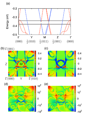
To analyze the contribution of each anticrossing point, next, we focus on the anticrossing points around the (0 1/2 1/2) point. In Fig. 4(a), there are two anticrossing points between Y and M points, and between M and Z points. In plane, such anticrossing points continuously form a closed loop around the M point. In Fig. 4(b) and (c), we show the -dependence of when the chemical potential is below and above the anticrossing points shown in black lines in Fig. 4(a), respectively. We see that the texture around the M point drastically changes when the chemical potential sweeps across the anticrossing points, which is consistent with the simple two-band calculationwakatsuki2014 . Note that around the other Fermi surfaces such as the one between -Y line are not negligible although the spin mixture is not so significant. This is because the effect of spin mixing extends away from anticrossing points; that is, has non-negligible values typically up to 0.2 - 0.3 eV away from anticrossing points. For comparison, in Fig. 4 (d) and (e), we show the Berry curvature, , which is the origin of intrinsic anomalous Hall conductivity (AHC)fang2003 ; nagaosa2010 . is defined as
| (7) |
where and are velocity operators. Since the spin mixing is important for both cases, there are common regions where the contributions to the DM interaction and AHC are large. However, in the Berry curvature, the summation in Eq. (7) is restricted to while it is not in Eq. (4). As a result, only the restricted region is important for AHC, which is in sharp contrast to .
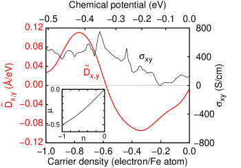
Figure 5 shows the resulting at K as a function of the carrier density together with the AHC, .
In the calculation, we use the rigid band approximation.
The relation between the carrier density, , and the chemical potential, , is shown in the inset of Fig. 5.
At eV, the number of hole is 1.0 per Fe atom, which corresponds to the carrier density in MnGe.
In Fig. 5, we find that shows clear sign change from FeGe to MnGe ,
which is consistent with the experimental sign change of skyrmion helicityshibata2013 ; grigoriev2013 ,
and is in sharp contrast to .
The positive (negative) hump structure in around () eV originates from the peak structure around () eV in Fig. 3, respectively.
If we assume that contributions from eV is negative (positive), we can understand why changes its sign around eV.
As for , the calculated value of in MnGe is larger than that in FeGe and there is no sign change.
This behavior including size and sign agrees well with the experimental anomalous Hall contribution to for MnGekanazawa2011 and for Mn1-xFexGekanazawa2014 .

Strain-induced huge anisotropy of the DM interaction.
According to the above discussion, there are several ways to change the size and sign of .
As we have seen above, can be efficiently controlled by carrier doping.
We can also exploit the temperature dependence of the exchange splitting.
When the relative position of up- and down- spin band changes, the distribution of anticrossing points in the band structure also changes, which will have a direct impact on .
As an example, we will show later the change in of FeGe as a function of the moment per Fe atom in Fig. 8 (b).
This mechanism can be related to the temperature dependence of the magnetic moment and skyrmion size in MnGekanazawa2011 .
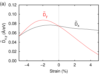
Another interesting possibility is to make use of the strain effect.
If we apply a strain to the system, the symmetry of the electronic structure can be lowered, and the distribution of the anticrossing points will change drastically.
This effect is expected to be prominent especially when changes its sign.
Figure 6 (a) shows the calculated at for which we apply the uniaxial strain along the direction.
We find that the difference between and actually enhances particularly by the elongation along the axis; is about 40 % (400 %) larger than at +2 % (+5%) strain.
The carrier density dependence of the anisotropy, , for fixed strain of +5% is shown in Fig. 6 (b).
We can see that the anisotropy becomes large particularly around the region of sign change.


Discussion
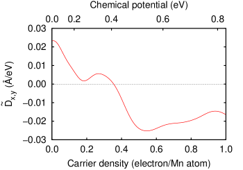
In the present calculation, we employed the rigid band approximation.
To examine its validity, we have performed a calculation for the other end material MnGe and doped negative carriers by the rigid band approximation.
As shown in Fig. 7, we have obtained a qualitatively similar result in that is positive (negative) for the end material MnGe (FeGe).
Thus the result that for Mn1-xFexGe changes its sign between and should be robust, even when we go beyond the rigid band approximation.
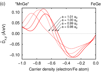
Regarding the crystal structure, it has been known that the magnetic moment for the optimized structure is much smaller than the experimental value within the local density approximationneef2009 . On the other hand, for the experimental structure, the size of magnetic moment is similar to that in the experiment (). In fact, within our calculations, the magnetic moment in FeGe decreases with decreasing the lattice constant as shown in Fig. 8 (a), which is consistent with previous studiesyamada2003 ; jarlborg2004 . As a result, exhibits non-trivial magnetic moment dependence as shown in Fig. 8 (b). Since the magnetic moment dependence of is also an important issue, let us next discuss how the change in the lattice structure or the magnetic moment affect in Mn1-xFexGe. In Fig. 8 (c), we plot the lattice constant dependence of , together with the distribution of band anti-crossings (d), (e) for lattice constants and , where is the experimental lattice constant. As can be seen, for larger and magnetic moment, the energy difference of two peaks in the histogram of Fig. 3 becomes larger (Fig. 8(e)). Consequently, the density at which changes its sign () becomes larger (Fig. 8(c)). However, the qualitative feature of is robust against the change in . Therefore, our calculation successfully explains why is positive (negative) for MnGe (FeGe), and provides a useful guideline for materials design of skyrmion crystal in metallic helimagnets.
| (expt.) | (calc.) | ||||
|---|---|---|---|---|---|
| (K) | (meVÅ2) | (Å) | (meVÅ) | (meVÅ) | |
| FeGe | 278 | 482 | 700 | -8.7 | -10.1 |
| MnGe | 170 | 295 | 30 | 124 | 107 |
Finally, let us compare the quantitative values of with experiments.
For this purpose, we should rescale using the exchange splitting as wakatsuki2014 .
Using eV for FeGe and eV for MnGe based on the calculation shown in Fig. 7, we can obtain meVÅ for FeGe and meVÅ for MnGe.
The experimental values of can be estimated using and the helical period, as .
Assuming that scales to and using the values of meVÅ2 and K for MnSiishikawa1977 ; freimuth2013 , the experimental values of for FeGe and MnGe are -8.7 meVÅ and 124 meVÅ, respectively, which are in good agreement with our results (see Table I).
Method
Crystal structure.
In the calculations, experimental values are used for the crystallographic parameterslebech1989 .
For the pressure and strain calculations, internal coordinates of the atoms are fixed and only the lattice parameters are modified.
To symmetrize and , we use two different internal coordinates of atoms in the (4a) position, that is, where and , and the one with its 90-degree rotation along the -axis and take the average.
Note that our structure is right-handed according to Ref. shibata2013, .
In the experiment, observed skyrmions on the right-handed crystal structure in FeGe (MnGe) are anticlockwise (clockwise), indicating that ().
DFT calculations.
To evaluate in FeGe, we perform the electronic structure calculation within the generalized-gradient approximation (GGA)pbe1996 based on the density functional theoryespresso .
We use ultrasoft pseudopotentialsvanderbilt1990 and plain-wave basis sets to describe the charge densities and wave functions with cutoff energies of 40Ry and 500Ry, respectively.
We use -point mesh.
With including the spin-orbit couplings and assuming the ferromagnetic moment along the axis, we obtain non-collinear magnetic structure.
Using this electronic structure, we calculate Wannier functions for Fe 3d and Ge 4p orbitals using wannier90 codemarzari1997 ; souza2001 ; mostofi2008 .
Based on the Wannier functions, we construct a tight-binding model on the restricted Hilbert space and calculate using k-point mesh at K.
The AHC is also calculated using the Wannier interpolation technique with k-point meshwang2006 .
References
- (1) Bogdanov, A. N. & Yablonskii, D. A. Thermodynamically stable “vortices” in magnetically ordered crystals. The mixed state of magnets. Sov. Phys. JETP 68, 101–103 (1989).
- (2) Rößler, U. K., Bogdanov, A. N. & Pfleiderer, C. Spontaneous skyrmion ground states in magnetic metals. Nature 442, 797–801 (2006).
- (3) Mühlbauer, S. et al. Skyrmion Lattice in a Chiral Magnet. Science 323, 915–919 (2009).
- (4) Yu, X. Z. et al. Real-space observation of a two-dimensional skyrmion crystal. Nature 465, 901–904 (2010).
- (5) Yu, X. Z. et al. Near room-temperature formation of a skyrmion crystal in thin-films of the helimagnet FeGe. Nature Materials 10, 106–109 (2011).
- (6) Nagaosa, N. & Tokura, Y. Topological properties and dynamics of magnetic skyrmions. Nature Nanotech. 8, 899–911 (2013).
- (7) Shibata, K. et al. Towards control of the size and helicity of skyrmions in helimagnetic alloys by spin-orbit coupling. Nature Nanotech. 8, 723–728 (2013).
- (8) Grigoriev, S. V. et al. Chiral Properties of Structure and Magnetism in Mn1-xFexGe Compounds: When the Left and the Right are Fighting, Who Wins? . Phys. Rev. Lett. 110, 207201 (2013).
- (9) Seki, S., Yu, X. Z., Ishiwata, S. & Tokura, Y. Observation of Skyrmions in a Multiferroic Material. Science 336, 198 (2012).
- (10) Janson, O. et al. The quantum nature of skyrmions and half-skyrmions in Cu2OSeO3. Nature Communications 5, 1–11 (2014).
- (11) Heide, M., Bihlmayer, G. & Blügel, S. Dzyaloshinskii-Moriya interaction accounting for the orientation of magnetic domains in ultrathin films: Fe/W(110). Phys. Rev. B 78, 140403 (2008).
- (12) Ferriani, P. et al. Atomic-Scale Spin Spiral with a Unique Rotational Sense: Mn Monolayer on W(001). Phys. Rev. Lett. 101, 027201 (2008).
- (13) Heide, M., Bihlmayer, G. & Blügel, S. Describing Dzyaloshinskii–Moriya spirals from first principles. Physica B: Phys. Cond. Matt. 404, 2678–2683 (2009).
- (14) Udvardi, L., Szunyogh, L., Palotás, K. & Weinberger, P. First-principles relativistic study of spin waves in thin magnetic films. Phys. Rev. B 68, 104436 (2003).
- (15) Ebert, H. & Mankovsky, S. Anisotropic exchange coupling in diluted magnetic semiconductors: Ab initio spin-density functional theory. Phys. Rev. B 79, 045209 (2009).
- (16) Katsnelson, M. I., Kvashnin, Y. O., Mazurenko, V. V. & Lichtenstein, A. I. Correlated band theory of spin and orbital contributions to Dzyaloshinskii-Moriya interactions. Phys. Rev. B 82, 100403 (2010).
- (17) Dmitrienko, V. E. et al. Measuring the Dzyaloshinskii–Moriya interaction in a weak ferromagnet. Nature Physics 10, 202–206 (2014).
- (18) Freimuth, F., Bamler, R., Mokrousov, Y. & Rosch, A. Phase-space Berry phases in chiral magnets: Dzyaloshinskii-Moriya interaction and the charge of skyrmions. Phys. Rev. B 88, 214409 (2013).
- (19) Freimuth, F., Blügel, S. & Mokrousov, Y. Berry phase theory of Dzyaloshinskii–Moriya interaction and spin–orbit torques. J. Phys.-Cond. Matt. 26, 104202 (2014).
- (20) Wakatsuki, R., Ezawa, M. & Nagaosa, N. Domain wall of a ferromagnet on a three-dimensional topological insulator. ArXiv:1412.7910.
- (21) Nagaosa, N., Sinova, J., Onoda, S., MacDonald, A. H. & Ong, N. P. Anomalous Hall effect. Rev. Mod. Phys. 82, 1539–1592 (2010).
- (22) Wäppling, R. & Häggström, L. Mossbauer study of cubic FeGe. Phys. Lett. A 28A, 173 (1968).
- (23) Lundgren, L., Blom, K. A. & Beckman, O. Magnetic susceptibility measurements on cubic FeGe. Phys. Lett. A 28A, 175 (1968).
- (24) Yamada, H., Terao, K., Ohta, H. & Kulatov, E. Electronic structure and magnetism of FeGe with B20-type structure. Physica B 329-333, 1131–1133 (2003).
- (25) Fang, Z. et al. The Anomalous Hall Effect and Magnetic Monopoles in Momentum Space. Science 302, 92–95 (2003).
- (26) Kanazawa, N. et al. Large Topological Hall Effect in a Short-Period Helimagnet MnGe. Phys. Rev. Lett. 106, 156603 (2011).
- (27) Kanazawa, N. Charge and heat transport phenomena in electronic and spin structures in B20-type compounds (2014). PhD thesis, Univ. of Tokyo.
- (28) Neef, M., Doll, K. & Zwicknagl, G. Ab initio study of pressure-induced metal-insulator transition in cubic FeGe. Phys. Rev. B 80, 035122 (2009).
- (29) Jarlborg, T. Electronic structure and magnetism for from supercell calculations. Journal of Magnetism and Magnetic Materials 283, 238–246 (2004).
- (30) Ishikawa, Y., Shirane, G., Tarvin, J. A. & Kohgi, M. Magnetic excitations in the weak itinerant ferromagnet MnSi. Phys. Rev. B 16, 4956 (1977).
- (31) Lebech, B., Bernhard, J. & Freltoft, T. Magnetic structures of cubic FeGe studied by small-angle neutron scattering. J. Phys. Cond. Matt. 1, 6105–6122 (1989).
- (32) Perdew, J. P., Burke, K. & Ernzerhof, M. Generalized Gradient Approximation Made Simple. Phys. Rev. Lett. 77, 3865 (1996).
- (33) Giannozzi, P. et al. QUANTUM ESPRESSO: a modular and open-source software project for quantum simulations of materials. J. Phys. Condens. Matter 21, 395502 (2009).
- (34) Vanderbilt, D. Soft self-consistent pseudopotentials in a generalized eigenvalue formalism. Phys. Rev. B 41, 7892 (1990).
- (35) Marzari, N. & Vanderbilt, D. Maximally localized generalized Wannier functions for composite energy bands. Phys. Rev. B 56, 12847–12865 (1997).
- (36) Souza, I., Marzari, N. & Vanderbilt, D. Maximally localized Wannier functions for entangled energy bands. Phys. Rev. B 65, 035109 (2001).
- (37) Mostofi, A. A. et al. wannier90: A tool for obtaining maximally-localised Wannier functions. Comp. Phys. Comm. 178, 685–699 (2008).
- (38) Wang, X., Yates, J., Souza, I. & Vanderbilt, D. Ab initio calculation of the anomalous Hall conductivity by Wannier interpolation. Phys. Rev. B 74, 195118 (2006).
Acknowledgements
The authors thank N. Kanazawa, W. Koshibae, D. Morikawa, K. Shibata, and Y. Tokura for helpful discussions.
This work is supported by Grant-in-Aids for Scientific Research (No. 24224009 and No. 25104711) from the Ministry of Education, Culture, Sports, Science and Technology (MEXT) of Japan, and ImPACT Program of Council for Science, Technology and Innovation (Cabinet Office, Government of Japan).
Author contributions
T.K. carried out the numerical calculations. T.K., N.N. and R.A. analyzed the results and wrote the paper.