4 \No1 \Month1 \Year2011
Kyoto, Kyoto, Kyoto, Kyoto
Graduate School of Informatics, Kyoto University, JapanKyoto
Digital Cancelation of Self-Interference for Single-Frequency Full-Duplex Relay Stations via Sampled-Data Control
Abstract
In this article, we propose sampled-data design of digital filters that cancel the continuous-time effect of coupling waves in a single-frequency full-duplex relay station. In this study, we model a relay station as a continuous-time system while conventional researches treat it as a discrete-time system. For a continuous-time model, we propose digital feedback canceler based on the sampled-data control theory to cancel coupling waves taking intersample behavior into account. We also propose robust control against unknown multipath interference. Simulation results are shown to illustrate the effectiveness of the proposed method.
keywords:
wireless communication, coupling wave cancelation, sampled-data control, optimization, relay station.002011 002011
1 Introduction
In wireless communications, relay stations have been used to relay radio signals between radio stations that cannot directly communicate with each other due to the signal attenuation. More recently, relay stations are used to achieve a certain spatial diversity called cooperative diversity to cope with fading channels [Laneman]. On the other hand, it is important to efficiently utilize the scarce bandwidth due to the limitation of frequency resources [Cov], while conventional relay stations commonly use different wireless resources, such as frequency, time and code, for their reception and transmission of the signals. For this reason, a single-frequency full-duplex relay station, in which signals with the same carrier frequency are received and transmitted simultaneously, is considered as one of key technologies in the fifth generation (5G) mobile communications systems [2020beyond]. In order to realize such full-duplex relay stations, self-interference caused by coupling waves is the key issue [Jain].
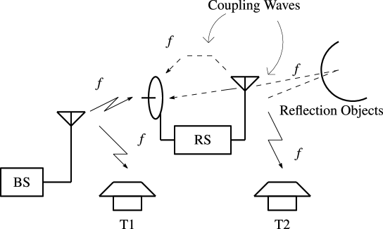
Fig. 1 illustrates self-interference by coupling waves. In this figure, radio signals with carrier frequency are transmitted from the base station (denoted by BS). One terminal (denoted by T1) directly receives the signal from the base station, but the other terminal (denoted by T2) is so far from the base station that they cannot communicate directly. Therefore, a relay station (denoted by RS) is attached between them to relay radio signals. Then, radio signals with the same carrier frequency are transmitted from RS to T2, but also they are fed back to the receiving antenna directly or through reflection objects. As a result, self-interference is caused in the relay station, which may deteriorate the quality of communication and, even worse, may destabilize the closed-loop system.
To tackle with the issue of self-interference cancelation, many methods have been proposed for single-frequency full-duplex systems. Analog cancelation has been proposed in [Rad, Knox], in which analog devices are used for canceling coupling waves. Since coupling wave paths are physically analog systems and there is no quantization problem, this design is theoretically the most ideal except for implementation issues. On the other hand, digital cancelation has attracted increasing attention, in which the interference is subtracted in the digital domain by using digital signal processing techniques [sakai2006simple, Dua, Gol, Chun, Snow, Haya13, Sen]. Digital cancelers benefit easy implementation on digital devices in exchange for the response between sampling instants. In addition, spatial domain techniques, called antenna cancelation, has been also proposed in [Jain, Kho], in which they try to reduce the interference by arranging antenna placement. See [Jain, Dua] for details.
For the problem of self-interference, a pre-nulling method [Chun] and adaptive methods [sakai2006simple, Haya13] have been proposed to cancel the effect of coupling waves. In these studies, a relay station is modeled by a discrete-time system, and the performance is optimized in the discrete-time domain. However, radio waves are in nature continuous-time signals and hence the performance should be discussed in the continuous-time domain. In other words, one should take account of intersample behavior for coupling wave cancelation.
In theory, if the signals are completely band-limited below the Nyquist frequency, then the intersample behavior can be restored from the sampled-data in principle [Shannon], and the discrete-time domain approaches might work well. However, the assumption of perfect band limitedness is hardly satisfied in real signals since
-
1.
real baseband signals are not fully band-limited,
-
2.
pulse-shaping filters, such as raised-cosine filters, do not act perfectly,
-
3.
and the nonlinearity in electric circuits adds frequency components beyond the Nyquist frequency.
One might think that if the sampling frequency is fast enough, then the assumption is almost satisfied and there is no problem. But this is not true; firstly, the sampling frequency cannot be arbitrarily increased in real systems, and secondly, even though the sampling is quite fast, intersample oscillations may happen in feedback systems [Yamamoto99-1, Sect. 7].
To solve the problem mentioned above, we propose a new design method for coupling wave cancelation based on the sampled-data control theory [Chen95, Yamamoto99-1]. We model the transmitted radio signals and coupling waves as continuous-time signals, and optimize the worst case continuous-time error due to coupling waves by a digital canceler. This is formulated as a sampled-data optimal control problem, which can be solved via the fast-sampling fast-hold (FSFH) method [Kel, Yamamoto1999729]. We also propose robust feedback cancelers that can take account of uncertainties in coupling wave path characteristic such as unknown multipath interference due to, for example, large structures that reflect radio waves, or the change of weather conditions [Tak]. Design examples are shown to illustrate the proposed methods.
The present manuscript expands on our recent conference contributions [SSHRsci, sasaharaSICE14] by incorporating robust feedback control into the formulation.
The remainder of this article is organized as follows. In Section 2, we derive a mathematical model of a relay station considered in this study. In Section 3, we propose sampled-data control for cancelation of self-interference. Here we also discuss robust control against uncertainty in the delay time. In Section LABEL:sec:sim, simulation results are shown to illustrate the effectiveness of the proposed method. In Section LABEL:sec:conc, we offer concluding remarks.
Notation
Throughout this article, we use the following notation. We denote by the Lebesgue space consisting of all square integrable real functions on endowed with norm . The symbol denotes the argument of time, the argument of Laplace transform and the argument of transform. These symbols are used to indicate whether a signal or a system is of continuous-time or discrete-time. The operator with nonnegative real number denotes the continuous-time delay operator with delay time . For a matrix , denotes the maximum singular value of .
2 Relay Station Model
In this section, we provide a mathematical model of a relay station with self-interference phenomenon.

Fig. 2 depicts a single-frequency full-duplex relay station implemented with a digital canceler [Knox]. A radio wave with carrier frequency from a base station is accepted at the receiving antenna and amplified by the low noise amplifier (LNA). Then, the received signal is demodulated to a baseband signal by the demodulator, and converted to a digital signal by the analog-to-digital converter (ADC). The obtained digital signal is then processed by the digital signal processor (DSP) into another digital signal, which is converted to an analog signal by the digital-to-analog converter (DAC). Finally, the analog signal is modulated to a radio wave with carrier frequency , amplified by the power amplifier (PA) and transmitted by the transmission antenna. A problem here is that the transmitted signal will again reach the receiving antenna. This is called coupling wave and causes self-interference, which deteriorates the communication quality.

Fig. 3 shows a simplified block diagram of the relay station. In Fig. 2, we model LNA and PA in Fig. 2 as static gains, and , respectively. The modulator is denoted by and the demodulator by . We assume that the coupling wave channel is a flat fading channel, that is, all frequency components of a signal through this channel experience the same magnitude fading. Then the channel can be treated as an all-pass system. In this study, we adopt a delay system, , as a channel model, where is the attenuation rate and is a delay time. The block named “Digital System” includes ADC, DSP and DAC in Fig. 2.
In this article, we consider the quadrature amplitude modulation (QAM),
which is used widely in digital communication systems, as a modulation method.
QAM transforms a transmission signal into two orthogonal carrier waves,
that is a sine wave and a cosine wave.
We assume the transmission signal is given by
{Meqnarray}
u(t) := ∑_k g(t-kh) [
u_k^Iu_k^Q
].
In this expression, is a general pulse-shaping function,
is the sampling period, and denote respectively the in-phase
and the quadrature components of a transmission symbol.
We assume that the support of the Fourier transform of
is finite and the bandwidth is much less than .
In other words, there exists a frequency () such that
for any .
Then the modulated signal can be written as [HayComm, Chap. 2]
{Meqnarray}
~u(t) &= M u(t)
= ∑_k g(t-kh) ( u_k^I cos2πft- u_k^Q sin2πft).
On the other hand,
the demodulation operator is a linear operator
satisfying [HayComm].
Fig. 4 shows the block diagram of .
In this block diagram, is the ideal low-pass filter with
cut-off frequency satisfying
{Meqnarray}
H_id(jω) = {1, if ω¡2πfc,0, otherwise.
The cut-off frequency is chosen to satisfy
.
By the linearity of ,
we obtain an equivalent block diagram shown in Fig. 5 to Fig. 3.
Here
{Meqnarray}
~u(t-L)
&= ∑_k g(t-L-kh) { (u_k^I cos(2πfL)
+ u_k^Q sin(2πfL)) cos(2πft)
+ (u_k^I sin(2πfL) - u_k^Q cos(2πfL)) sin(2πft)}.
Thus, we have
{Meqnarray}
& cos(2πft) ⋅~u(t-L)
=12 ∑_k g(t-L-kh) { u_k^I cos(2πfL)
+ u_k^Q sin(2 πfL)
+(u_k^I cos(2πfL) + u_k^Q sin(2πfL)) cos(4 πft)
+(u_k^I sin(2πfL) - u_k^Q cos(2πfL)) sin(4 πft) }.
From this, we have
{Meqnarray}
& 2H_id[cos(2πft) ⋅~u(t-L)]
= ∑_k g(t-L-kh) {u_k^I cos(2πf L) + u^Q_k sin(2πf L)}.
In the same way, we have
{Meqnarray}
& 2H_id[-sin(2πft) ⋅~u(t-L)]
= ∑_k g(t-L-kh) {-u_k^I sin(2πf L) + u^Q_k cos(2πf L)}.
Finally, we have the following relation:
{Meqnarray}
u_L(t) &= D( a_1ra_2 ~u(t-L) )
= αA_L u(t-L),
where and
{Meqnarray}
A_L := [
cos(2πfL)sin(2πfL)-sin(2πfL)cos(2πfL)
].


Finally we obtain a relay station model depicted in Fig. 6. By this figure, we can see that the relay station with self-interference is a feedback system. In practice, the gain of PA in Fig. 2 is very high (e.g., ) and the loop gain becomes much larger than , and hence we should discuss the stability as well as self-interference cancelation. To achieve these requirements, we design the digital controller in the digital system, which is precisely shown in Fig. 7.


In Fig. 7, ADC in Fig. 2 is modeled by an anti-aliasing analog filter with an ideal sampler with sampling period , defined by {Meqnarray} S_h : { y_0(t) } ↦{ y_d[n] } : y_d[n] = y_0(nh),n = 0,1,2,…. For the DSP block in Fig. 2, we assume a digital filter denoted by , which we design for self-interference cancelation. DAC in Fig. 2 is modeled by a zero-order hold, , defined by {Meqnarray} H_h : {u_d[n]} ↦{u_0(t)}:u_0(t)=u_d[n],t ∈[nh, (n+1)h), n=0,1,2,…, and a post analog low-pass filter denoted by . We assume that and are proper, stable and real-rational transfer function matrices. Note that a strictly proper function is normally used for and it is included in the assumption.
3 Feedback Control
Fig. 8 shows the block diagram of the feedback control system of the relay station.

For this system, we find the digital controller, , that stabilizes the feedback system and also minimize the effect of self-interference, , for any . To obtain a reasonable solution, we restrict the input continuous-time signal to the following set {Meqnarray} WL^2 := {v=Ww:w ∈L^2, ∥w ∥_2 = 1}, where is a continuous-time LTI system with real-rational, stable, and strictly proper transfer function . Under this assumption, we first solve a nominal control problem where all system parameters are previously known. Then we propose a robust controller design against uncertainty in the coupling wave paths.
3.1 Nominal Controller Design
Here we consider the nominal controller design problem formulated as follows:
Problem 1
Find the digital controller (canceler) that stabilizes the feedback system in Fig. 8 and uniformly minimizes the norm of the error for any .
This problem is reducible to a standard sampled-data control problem [Chen95, Yamamoto99-1]. To see this, let us consider the block diagram shown in Fig. 9. Let be the system from to . Then we have {Meqnarray} z = v-u = T_zww and hence uniformly minimizing for any is equivalent to minimizing the norm of , {Meqnarray} ∥ T_zw∥_∞ = sup_w ∈L^2, ∥w ∥_2 = 1 ∥T_zw w ∥_2.
Let be a generalized plant given by {Meqnarray} Σ(s) = [ W(s)-P(s)F(s)W(s)αe^-LsA_LF(s)P(s) ]. By using this, we have {Meqnarray} T_zw(s) = F(Σ(s), H_h K(z) S_h), where denotes the linear-fractional transformation (LFT) [Chen95]. Fig. 10 shows the block diagram of this LFT. Then our problem is to find a digital controller that minimizes . This is a standard sampled-data control problem, and can be efficiently solved via FSFH approximation [Kel, Nagahara13-2, Yamamoto1999729].


Note that if there exists a controller that minimizes , then the feedback system is stable and the effect of self-interference is bounded by the norm. We summarize this as a proposition.
Proposition 1
Assume with . Then the feedback system shown in Fig. 8 is stable, and for any we have .
Proof
First, if the feedback system is unstable, then the norm becomes unbounded. Next, for there exists such that and . Then, inequality gives {Meqnarray} ∥v-u∥_2 = ∥T_zww∥_2 ≤∥T_zw∥_∞ ∥w∥_2 ≤γ.
3.2 Robust Controller Design against Multipath Interference
In practice, the characteristic of the coupling wave channel changes due to, for example, large structures that reflect radio waves. In this situation, it is difficult to predict the coupling wave paths beforehand, and hence there must be uncertainties in the paths. Under this uncertainty, the nominal controller may lead to deterioration of cancelation performance, and even worse, it may make the feedback system unstable. To solve this problem, we propose robust controller design against the uncertainty.
Let us assume the characteristic of the coupling wave paths in Fig. 6 is perturbed as {Meqnarray} r e^-Ls ↦r e^-Ls + ∑i=1M ri e-Lis, where and are the attenuation ratio and the delay time of the -th path, respectively. Note that represents the number of additional paths. Since the additional paths are detour paths, we assume {Meqnarray} L_i ¿ L, i=1,2,…,M. Then the characteristic of the feedback path in Fig. 8 is perturbed as {Meqnarray} αe^-LsA